Page 2 - Instructions; General safety instructions
Instructions 4 1 Instructions 1.1 General safety instructions Risk of personal injury • During use the appliance becomes hot. Care should be taken to avoid touching heating elements inside the ovens. • Protect your hands by wearing oven gloves when moving food inside the oven. • Never try to put out...
Page 4 - Risk of damaging the appliance
Instructions 6 Risk of damaging the appliance • This appliance must not be installed behind a decorative door. • Do not use abrasive or corrosive detergents (e.g. scouring powders, stain removers and metallic sponges) on glass parts. • Use wooden or plastic utensils.• Racks and trays should be inser...
Page 5 - Installation
Instructions 7 EN • If any liquid does boil over or spill, remove the excess from the hob. • Take care not to spill acid substances such as lemon juice or vinegar on the hob. • Do not put empty pans or frying pans on switched on cooking zones. • Do not use steam jets to clean the appliance. • Do not...
Page 6 - For this appliance
Instructions 8 • At the end of the installation, check for any leaks with a soapy solution, never with a flame. • Have the electrical connection performed by authorised technical personnel. • The appliance must be connected to earth in compliance with electrical system safety standards. • Use cables...
Page 7 - Identification plate
Instructions 9 EN • This appliance is not intended to be operated by means of external timer or separate remote control system. • Do not use a steam cleaner to clean this appliance. • Do not use harsh abrasive cleaners or sharp metal scrapers to clean the oven glass door since they can scratch the s...
Page 8 - Manufacturer’s liability
Instructions 10 1.3 Manufacturer’s liability The manufacturer declines all liability for damage to persons or property caused by:• Use of the appliance other than that specified • Failure to comply with the instructions in the user manual • Tampering with any part of the appliance • The use of non-o...
Page 9 - How to read the user manual
Instructions 11 EN 1.7 How to read the user manual This user manual uses the following reading conventions: 1. Sequence of instructions for use.• Standalone instruction. Instructions General information on this user manual, on safety and final disposal. Description Description of the appliance and i...
Page 10 - Description; General Description
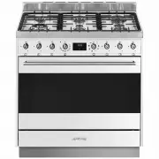
Description 12 2 Description 2.1 General Description 1 Backguard 2 Cooktop 3 Control panel 4 Oven light 5 Seal 6 Door 7 Fan 8 Storage compartment Rack/tray support frame shelf
Page 11 - AUX
Description 13 EN 2.2 Cooktop AUX = Auxiliary SR = Semi-rapid R = Rapid UR2 = Ultra rapid 2.3 Control panel 1 Cooktop burner knobs Useful for lighting and adjusting the cooktop burners.Press and turn the knobs anti-clockwise to the value to light the relative burners. Turn the knobs to the zone betw...
Page 12 - Available accessories; Useful when using a wok.
Description 14 4 Programmer clock Useful for displaying the current time, setting programmed cooking operations and programming the minute minder timer. 5 Function knob The oven's various functions are suitable for different cooking modes. After selecting the required function, set the cooking tempe...
Page 13 - Deep tray
Description 15 EN Deep tray Useful for collecting fat from foods placed on the rack above. Rack Useful for supporting containers with food during cooking. Rack Useful for supporting containers with food during cooking. The accessories intended to come into contact with food are made of materials tha...
Page 14 - Use
Use 16 3 Use Instructions High temperature inside the oven during use Danger of burns • Keep the oven door closed during cooking. • Protect your hands wearing heat resistant gloves when moving food inside the oven. • Do not touch the heating elements inside the oven. • Do not pour water directly ont...
Page 15 - Escaping gas may cause an explosion.
Use 17 EN Escaping gas may cause an explosion. If you smell gas or notice any faults in the gas installation:• Immediately shut off the gas supply or close the gas cylinder valve. • Immediately extinguish all naked flames and cigarettes. • Do not use any light or appliance switches and do not pull a...
Page 16 - Using the accessories; Ring reducers
Use 18 3.2 Using the accessories Ring reducers The ring reducers have to be placed on the cooktop grids. Make sure they are placed properly. Racks and trays Racks and trays have to be inserted into the side guides until they come to a complete stop.• The mechanical safety locks that prevent the rack...
Page 17 - Using the cooktop; Practical tips for using the cooktop
Use 19 EN 3.3 Using the cooktop All the appliance's control and monitoring devices are located together on the front panel. The burner controlled by each knob is shown next to the knob. The appliance is equipped with an electronic ignition device. Simply press the knob and turn it anti-clockwise to ...
Page 18 - Using the storage compartment; Switching on the oven
Use 20 3.4 Using the storage compartment There is a storage compartment located at the bottom of the cooker; this can be used to store pans or metal objects required to use the cooker.Press lightly on the sides of the door to open it. 3.5 Using the oven Switching on the oven To switch on the oven:1....
Page 20 - General advice
Use 22 3.6 Cooking advice General advice • Use a fan assisted function to achieve consistent cooking at several levels. • It is not possible to shorten cooking times by increasing the temperature (the food could be overcooked on the outside and undercooked on the inside). Advice for cooking meat • C...
Page 21 - Setting the time
Use 23 EN 3.7 Programmer clock Value decrease key Clock key Value increase key Setting the time On the first use, or after a power failure, the digits will be flashing on the appliance’s display. 1. Hold down the clock key for two seconds. The dot between the hours and the minutes flashes. 2. The ti...
Page 22 - Timed cooking
Use 24 Timed cooking 1. Keep the clock key pressed until the symbol appears. 1. Press the clock key again. On the display the symbol and the text appear, alternating with the current time. 2. Use the value increase and value decrease keys to set the required minutes of cooking. 3. Select a function ...
Page 23 - Minute minder timer
Use 25 EN 5. Press the menu key . The text will appear on the display in sequence with the pre-set cooking duration added to the current time (for example, the cooking end time shown is 18:30). 6. Press the or key to set the cooking end time. (for example, 19:30). 7. Wait approx. 7 seconds without p...
Page 24 - Modifying the set data
Use 26 5. Press the value decrease key to turn the buzzer off. Modifying the set data 1. Press the clock key . 2. Use the value increase and value decrease keys to set the number of minutes required. Deleting the set data 1. Press the clock key . 2. Hold down the value increase and value decrease ke...
Page 25 - Cooking information table
Use 27 EN Cooking information table Food Weight (Kg) Function Runner posi-tion from the bottom Temperature (°C) Time (minutes) Lasagne 3 - 4 Convection 1 220 - 230 45 - 50 Pasta bake 3 - 4 Convection 1 220 - 230 45 - 50 Roast veal 2 Fan assisted/Fan forced 2 180 - 190 90 - 100 Pork 2 Fan assisted/Fa...
Page 26 - Cleaning and maintenance; Cleaning the appliance; Cleaning the cooktop
Cleaning and maintenance 28 4 Cleaning and maintenance Instructions 4.1 Cleaning the appliance Recommendations for cleaning the cooktop To keep the surfaces in good condition, they should be cleaned regularly after use. Let them cool first. Cleaning the cooktop 1. Pour some non-abrasive detergent on...
Page 27 - Cleaning the igniters and thermocouples; Removing the door; Grasp the door on both sides with both
Cleaning and maintenance 29 EN Cleaning the igniters and thermocouples • If necessary, clean the igniters and thermocouples with a damp cloth. • If there is any dry residue, remove it with a toothpick or needle. Recommendations for cleaning the oven cavity For the best oven upkeep, clean it regularl...
Page 28 - To reassemble the door, put the hinges; Cleaning the door glazing; Removing the internal glass panes
Cleaning and maintenance 30 3. To reassemble the door, put the hinges in the relevant slots in the oven, making sure that grooved sections A are resting completely in the slots. Lower the door and once it is in place remove the pins from the holes in the hinges. 4.3 Cleaning the door glazing The gla...
Page 29 - Removing racks/trays support frames
Cleaning and maintenance 31 EN 4. Clean the external glass pane and the panes previously removed. Use absorbent kitchen roll. In case of stubborn dirt, wash with a damp sponge and neutral detergent. 5. Refit the panes in the reverse order in which they were removed. 6. Reposition the internal glass ...
Page 30 - Preliminary operations
Cleaning and maintenance 32 4.4 Vapour Clean Preliminary operations Before starting the Vapour Clean function:• Completely remove all accessories from inside the oven. • Pour approximately 400 cc of water onto the cavity bottom. Make sure it does not overflow out of the cavity. • Spray a water and w...
Page 31 - Vapour Clean setting; Extraordinary maintenance; Removing and installing the oven seal
Cleaning and maintenance 33 EN Vapour Clean setting 1. Turn the function knob to the symbol and the temperature knob to the symbol . 2. Set a cooking time of 18 minutes using the programmer clock. The Vapour Clean cycle starts a few seconds after the last press on the programmer clock keys.3. At the...
Page 32 - Replacing the oven light bulb
Cleaning and maintenance 34 Replacing the oven light bulb 1. Completely remove all accessories from inside the oven. 2. Remove the racks/trays support frames. 3. Remove the bulb cover using a tool (e.g. a screwdriver). 4. Slide out and remove the light bulb. 5. Fit the new light bulb. 6. Refit the c...
Page 33 - The appliance does not work.
Cleaning and maintenance 35 EN What to do if... The appliance does not work. • The circuit breaker is faulty: look in the fuse box and check that the circuit breaker is in working order. • Power cut: check whether the kitchen light works. The gas burner does not ignite. • Power cut or damp ignition ...
Page 34 - Installation; Minimum clearance to combustible surfaces; Freestanding cooker
Installation 36 5 Installation 5.1 Minimum clearance to combustible surfaces Freestanding cooker A 600 mm (Overhead) measured from the highest part of the highest burner and 750 mm for an exhaust fan. B 200 mm (Vertical combustible surface) measured form the edge of the nearest burner. C 10 mm (Hori...
Page 35 - The regulator must be fitted to the 1⁄2
Installation 37 EN as a separate fitting in the case of ULPG (propane) appliances.Connection of the appliance to the gas supply must be in accordance with the requirements of AS5601. A ½” BSP connector at the inlet is recommended and the gas supply line to the appliance must be of adequate length to...
Page 36 - Connection to liquid gas
Installation 38 Connection to liquid gas Use a pressure regulator and make the connection on the gas cylinder following the guidelines set out in the regulations in force.Make sure that the supply pressure complies with the values indicated in the “Burner and nozzle characteristics table” section. R...
Page 37 - Adaptation to different types of; Replacing nozzles
Installation 39 EN 5.3 Adaptation to different types of gas In case of operation with other types of gas, the burner nozzles must be changed and the minimum flame adjusted on the gas cocks. Replacing nozzles 1. Remove the pan stands, burner caps and flame-spreader crowns to access the burner casings...
Page 38 - Lubrication of gas cocks
Installation 40 Lubrication of gas cocks Over time the gas cocks may become difficult to turn and get blocked. Clean them internally and replace the lubrication grease. Burner and nozzle characteristics table Overall dimensions Location of gas and electrical connection points. The greasing of the ga...
Page 39 - General information
Installation 41 EN 5.4 Positioning General information This appliance may be installed next to walls, one of which must be higher than the worktop, at a minimum distance of 50 mm from the side of the appliance, as shown in figures A and C relative to the installation classes.Any wall units positione...
Page 40 - Positioning and levelling
Installation 42 B - Class 2 subclass 1 (Built-in appliance) C - Class 2 subclass 1 (Built-in appliance) Positioning and levelling • After making the gas and electrical connections, screw on the four feet supplied with the appliance. The appliance must sit level on the floor to ensure stability.• Scr...
Page 41 - Assembling the backguard
Installation 43 EN Assembling the backguard The backguard must always be positioned and secured correctly on the appliance.1. Loosen the 4 screws ( A ) on the back of the cooktop (2 for each side) using a screwdriver. 2. Place the backguard on the worktop. 3. Align the slots of the backguard ( B ) w...
Page 42 - Fastening to the wall
Installation 44 Fastening to the wall 1. Screw the wall fastening plate to the rear of the appliance. 2. Adjust the height of the 4 feet. 3. Assemble the fastening bracket. 4. Align the base of the hook on the fastening bracket with the base of the slot on the wall fastening plate. The anti-tip devi...
Page 43 - Align the base of the fastening bracket
Installation 45 EN 5. Align the base of the fastening bracket with the ground and tighten the screws to fix the measurements. 6. Use 50 mm for the distance from the side of the appliance to the bracket holes. 7. Move the bracket onto the wall and mark the position of the holes to be drilled in the w...
Page 44 - Wall fixing
Installation 46 Wall fixing 1. Turn the screw placed behind the cooktop near the gas connection. 2. Attach the chain to the cooker with the screw just removed. 3. Stretch it out horizontally so that the other end of the chain touches the wall. 4. Mark the wall in the position where the hole is to be...
Page 45 - Electrical connection
Installation 47 EN 5.5 Electrical connection General information Check the grid characteristics against the data indicated on the plate.The identification plate bearing the technical data, serial number and brand name is visibly positioned on the appliance.Do not remove this plate for any reason.Per...
Page 46 - For the installer
Installation 48 5.6 For the installer • The plug must remain accessible after the installation is complete. Do not kink or trap the mains connection cable. • The appliance must be fitted according to the installation diagrams. • Do not attempt to turn or stress the threaded elbow on the manifold. Yo...