Jet 714000 - User Manual
Jet 714000 Band Saw – User Manual, read for free online in PDF format. We hope this helps you resolve any issues you may have. If you have further questions, please contact us through the contact form.


Table of Contents:
- Page 2 – WARNING – To reduce risk of injury:
- Page 3 – SAVE THESE INSTRUCTIONS; About this manual
- Page 4 – Table of contents; Section
- Page 5 – Features; Specifications
- Page 6 – Unpacking; Contents of shipping container; Tools required for assembly
- Page 7 – Assembly; Stand assembly; Table installation
- Page 8 – Guide rail and fence; Installation; Quick-tension handle; Electrical connections; GROUNDING INSTRUCTIONS
- Page 9 – Extension cords; Adjustments; Tilting table
- Page 10 – 0o Table Stop Adjustment; Adjusting table stop; Changing blades
- Page 11 – Adjusting blade tension; Adjusting blade tracking; Upper blade guide positioning
- Page 12 – Thrust bearing adjustment; Guide bearing adjustment; Miter gauge adjustment
- Page 13 – Operating controls; Replacing drive belt
- Page 15 – JWB-10 Band Saw – Exploded View
- Page 16 – JWB-10 Stand Assembly – Exploded View
- Page 17 – JWB-10 Band Saw and Stand – Parts List; Index No Part No
- Page 20 – Electrical Connections for JWB-10 Band Saw
- Page 21 – Warranty and service
Operating Instructions and Parts Manual
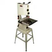
10-inch Band Saw
Model JWB-10
JET
427 New Sanford Road
LaVergne, Tennessee 37086
Part No. M-714000
Ph.: 800-274-6848
Edition 1 12/2015
www.jettools.com
Copyright © 2015 JET
This .pdf document is bookmarked
"Loading the manual" means you need to wait until the file loads and becomes available for online reading. Some manuals are very large, and the time they take to appear depends on your internet speed.
Summary
1.0 IMPORTANT SAFETY INSTRUCTIONS WARNING – To reduce risk of injury: 1. Read and understand the entire owner’s manual before attempting assembly or operation. 2. Read and understand the warnings posted on the machine and in this manual. Failure to comply with all of these warnings may cause serious...
3 25. Use the right tool at the correct speed and feed rate. Do not force a tool or attachment to do a job for which it was not designed. The right tool will do the job better and more safely. 26. Use recommended accessories; improper accessories may be hazardous. 27. Maintain tools with care. Keep ...
4 3.0 Table of contents Section Page 1.0 IMPORTANT SAFETY INSTRUCTIONS ....................................................................................................... 2 2.0 About this manual ......................................................................................................