Page 4 - Table of contents; Section
4 2.0 Table of contents Section Page 1.0 IMPORTANT SAFETY INSTRUCTIONS ....................................................................................................... 2 2.0 Table of contents ......................................................................................................
Page 5 - About this manual
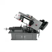
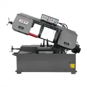
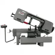
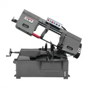
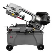
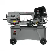
5 3.0 About this manual This manual is provided by JET ® , covering the safe operation and maintenance procedures for a JET Model MBS-1018 Mitering Band Saw. This manual contains instructions on installation, safety precautions, general operating procedures, maintenance instructions and parts breakd...
Page 6 - Specifications
6 4.0 Specifications Model number ................................................................. MBS-1018-1 ............................................... MBS-1018-3 Stock number .......................................................................... 413411 ......................................
Page 7 - Base hole centers
7 1 subject to local and national electrical codes 2 The specified values are emission levels and are not necessarily to be seen as safe operating levels. As workplace conditions vary, this information is intended to allow the user to make a better estimation of the hazards and risks involved only. ...
Page 8 - Setup and assembly; Shipping contents; Electrical connections
8 Read and understand all assembly instructions before attempting assembly. Failure to comply may cause serious injury. 5.0 Setup and assembly Disconnect band saw from power during setup. 5.1 Shipping contents 1 Band saw 1 Tool box containing: 4 Leveling pads 4 Hex cap bolts, 1/2 x 2 in. 4 Hex nuts,...
Page 9 - GROUNDING INSTRUCTIONS; Extension cords
9 Before connecting to power source, be sure switch is in off position. 6.1 GROUNDING INSTRUCTIONS This tool must be grounded. In the event of a malfunction or breakdown, grounding provides a path of least resistance for electric current to reduce the risk of electric shock. This tool is equipped wi...
Page 10 - Adjustments; Blade installation and removal; Close; Bracket adjustment; Blade tension and tracking; Tension
10 7.0 Adjustments Disconnect machine from power source before making adjustments, unless indicated otherwise. 7.1 Blade installation and removal Refer to Figure 7-1. Always wear leather gloves when handling blades to avoid injury. A blade (1in. W x 144in. L) is pre-installed and tensioned on saw. T...
Page 11 - Tracking; Blade speed change
11 If tension mechanism will not move blade, loosen and then re-tighten socket head cap screws on gibs (X, Figure 7-3). 7.4.2 Tracking Tracking is performed with wheel covers open and blade moving. Use extreme caution so that you do not come into contact with blade. Blade tracking has been set by ma...
Page 12 - Vise adjustment; Bow swivel adjustment
12 Figure 7-4: belt de-tensioning Figure 7-5: belt positioning 7.6 Vise adjustment Refer to Figure 7-6. The workpiece is placed between the vise jaws with required amount to be cut-off extending past the blade. To position floating jaw, lift rack block (R) and slide jaw into general position. Lower ...
Page 13 - Coolant flow; Control panel; Operation; Automatic shut-off; Cut completion; Auxiliary coolant hose
13 7.9 Coolant flow Coolant pump must be submerged before operating to prevent damage to pump. The blade guides are fitted with coolant valves. Coolant is provided to the fittings through interconnecting tubing, and is dispensed directly onto saw blade. Adjust coolant flow valves atop blade guide br...
Page 14 - General operating procedure; Evaluating cutting efficiency
14 4. Select proper speed and feed rate for material being cut. 5. Material to be cut must be securely held in vise. 6. Check to see that coolant level is adequate and turn on coolant pump if material to be cut requires it. Machine should be filled with approximately 15 L (4 gal.) of proper coolant ...
Page 15 - Blade break-in procedures; General cleaning; Hydraulic system; Belt replacement
15 For very high production on cutting of special materials, or to work hard-to-cut materials such as stainless steel, tool steel, or titanium, ask your industrial distributor for more specific blade recommendations. Also, the supplier who provides the workpiece material should be prepared to provid...
Page 16 - Additional servicing; Troubleshooting MBS-1018 Band Saw; Premature blade dulling
16 10.4 Additional servicing Any additional servicing should be performed by authorized service personnel. 11.0 Troubleshooting MBS-1018 Band Saw Symptom Possible Cause Correction* Excessive blade breakage Material loose in vise. Clamp work securely. Incorrect speed or feed. Check machinery handbook...
Page 17 - Reduce blade speed and feed pressure.; Replacement Parts
17 Symptom Possible Cause Correction* Bad cuts (rough) Blade speed too high for feed pressure. Reduce blade speed and feed pressure. Blade too coarse. Replace with finer blade. Blade is twisting Blade is binding in the cut. Decrease feed pressure. Blade tension too high. Decrease tension on blade Un...
Page 28 - Electrical Connections
28 13.0 Electrical Connections 13.1 Wiring Diagram for MBS-1018-1 K1,K2 – contactor LS4 – limit switch M1 – main motor M2 – coolant pump OL1 – overload PB1 – emergency stop button PB2,PB3 – pushbutton TR – transformer
Page 30 - Warranty and service
30 14.0 Warranty and service JET ® warrants every product it sells against manufacturers’ defects. If one of our tools needs service or repair, please contact Technical Service by calling 1-800-274-6846, 8AM to 5PM CST, Monday through Friday. Warranty Period The general warranty lasts for the time p...