Jet 414478 - User Manual
Jet 414478 Band Saw – User Manual, read for free online in PDF format. We hope this helps you resolve any issues you may have. If you have further questions, please contact us through the contact form.


Table of Contents:
- Page 2 – Warranty and Service
- Page 3 – Table of contents; Section
- Page 4 – Safety Warnings; General Cautions; General Machinery Warnings
- Page 6 – About this machine and manual; Specifications
- Page 8 – Machine setup; Uncrating and spotting; Electrical connections; Operating instructions; Controls; Setting blade speed
- Page 9 – Raising/lowering saw head; Evaluating cutting efficiency
- Page 10 – Work setup; Securing workpiece for square; Adjusting vise for angle cuts
- Page 11 – Installation and adjustment of; Starting the Saw
- Page 12 – Coolant flow; Coolant mixture and quantity; Adjustments; Blade tracking adjustment; Factory or field procedure
- Page 13 – Blade guide bearing adjustment
- Page 14 – Maintenance; Cleaning
- Page 15 – Lubrication; Changing blades; Changing drive belt
- Page 17 – Replacing carbide blade guide; Replacing guide bearings; Replacing wire brush
- Page 19 – Replacement Parts
- Page 28 – Electrical Connections
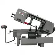
Operating Instructions and Parts Manual
10
”
x 16
”
Horizontal Band Saw
Models J-7020, J-7040
JET
427 New Sanford Road
LaVergne, Tennessee 37086
Part No. M-414472
Ph.: 800-274-6848
Revision D 01/2016
www.jettools.com
Copyright © 2016 JET
This .pdf document is bookmarked
"Loading the manual" means you need to wait until the file loads and becomes available for online reading. Some manuals are very large, and the time they take to appear depends on your internet speed.
Summary
2 1.0 Warranty and Service JET warrants every product it sells against manufacturers’ defects. If one of our tools needs service or repair, please contact Technical Service by calling 1-800-274-6846, 8AM to 5PM CST, Monday through Friday. Warranty Period The general warranty lasts for the time perio...
3 2.0 Table of contents Section Page 1.0 Warranty and Service ..................................................................................................................................... 2 2.0 Table of contents .................................................................................
3.0 Safety Warnings General Cautions - Misuse of this machine can cause serious injury. - For safety, the machine must be set up, used and serviced properly. - Read, understand and follow the instructions in the operator’s and parts manual which was shipped with your machine. When setting up the mac...