Page 2 - Warranty and Service
2 1.0 Warranty and Service JET warrants every product it sells against manufacturers’ defects. If one of our tools needs service or repair, please contact Technical Service by calling 1-800-274-6846, 8AM to 5PM CST, Monday through Friday. Warranty Period The general warranty lasts for the time perio...
Page 3 - Table of Contents; Section
3 2.0 Table of Contents Section Page 1.0 Warranty and Service ............................................................................................................................................. 2 2.0 Table of Contents .........................................................................
Page 4 - Safety Warnings
4 3.0 Safety Warnings 1. Read and understand the entire owner’s manual before attempting assembly or operation. 2. Read and understand the warnings posted on the machine and in this manual. Failure to comply with all of these warnings may cause serious injury. 3. Replace the warning labels if they b...
Page 5 - About this manual
5 26. Use the right tool at the correct speed and feed rate. Do not force a tool or attachment to do a job for which it was not designed. The right tool will do the job better and more safely. 27. Use recommended accessories; improper accessories may be hazardous. 28. Maintain tools with care. Keep ...
Page 6 - Features; Specifications
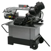
6 5.0 Features Figure 1 1. Blade tension handle 2. Cast iron bow 3. Coolant taps 4. Centralized control switch 5. 3-speed gearbox 6. 1HP motor 7. Ball bearing blade guides 8. Chip brush 9. Hydraulic cylinder with valve regulator 10. Adjustable work stop 11. Steel stand with coolant tank 12. Chip gui...
Page 8 - Set-Up and Assembly; Unpacking and cleanup
8 7.0 Set-Up and Assembly 7.1 Unpacking and cleanup Inspect contents of shipping container for shipping damage. Report any damage to your distributor. Remove all contents from carton, and compare to the contents list in this manual. Report any part shortages to your distributor. Do not discard carto...
Page 9 - Assembly
9 Figure 4 7.3 Assembly Refer to Figure 4. Band Saw should be disconnected from electrical power during assembly and setup. 1. Assemble base parts (J,K) according to Figure 4. 2. Install axle and wheels (H, I ). Install cotter pin (HP-9) through hole in axle, and bend back legs of cotter pin to secu...
Page 10 - Vertical cutting plate; Vertical support post
10 7.4 Vertical cutting plate These steps are only necessary when using band saw in vertical position. 1. Disconnect machine from power source. 2. Open valve on hydraulic cylinder (lever parallel to cylinder) and raise bow to vertical position. 3. Remove two screws and remove seat plate, as shown in...
Page 11 - Coolant system; Electrical connections; Grounding instructions
11 7.6 Coolant system Make sure there is coolant in the tank before operating, to prevent damage to pump. Use of a water-soluble coolant will increase cutting efficiency and prolong blade life. Do not use black cutting oil as a substitute. 1. Remove coolant return hose (A, Figure 10) from filter cup...
Page 13 - Adjustments; Squaring blade to table
13 9.0 Adjustments The settings on your band saw, such as blade squareness and tracking, were carefully performed by the manufacturer. You should, however, verify these before operating, in case misalignment has occurred during shipping. 9.1 Squaring blade to table 1. Disconnect machine from power s...
Page 14 - Miter cuts; Setting feed rate; Counterbalance spring
14 9.4 Miter cuts 1. Loosen handle (G, Figure 17). 2. Rotate bow to desired angle up to 45-degrees, using scale indicator on front of base. 3. Tighten handle. Figure 17 The angle scale is sufficient for most mitering operations. If greater precision is needed, verify setting with a protractor. If ha...
Page 15 - Blade tension
15 2. Raise bow to vertical position, and secure in place by turning off hydraulic cylinder. 3. Remove red blade guard (A, Figure 19) by removing two screws. Red blade guard must be reinstalled after new blade is fitted. Figure 19 4. Remove brush assembly (B, Figure 19) by removing two screws. 5. Lo...
Page 16 - Test cutting to verify adjustment
16 Blade tracking has been tested at the factory. Adjustment is rarely required when the blade is used properly and if the blade is correctly welded. If a tracking problem occurs, first inspect blade condition, then adjust tracking as follows: 1. Raise bow to vertical position and secure by turning ...
Page 17 - Setting blade speed; Blade guide adjustment; Chip brush
17 9.11 Setting blade speed 1. Turn machine OFF. 2. Turn lever (Figure 23) to desired setting: #1 – 145 sfpm #2 – 200 sfpm #3 – 245 sfpm Do not change blade speed during cutting operation. Figure 23 Material chips or shavings are the best indicator of proper blade speed and downfeed rate. See sectio...
Page 18 - Limit switch; Operating controls; Pre-Operation inspection; General operating procedure
18 9.14 Limit switch The stop screw (F, Figure 27) activates a limit switch to shut off the saw when it reaches down position. The stop screw has been set at the factory. If future adjustment is needed, loosen the hex nut and rotate the screw, then retighten the hex nut. Figure 27 10.0 Operating con...
Page 19 - Evaluating cutting efficiency; Maintenance
19 2. Place workpiece in vise and tighten vise. The workpiece should be fitted directly between the jaws without adding other objects. When workpiece to be cut is a profiled section, flat piece or special shape, refer to examples in Figure 29 for proper clamping positions. The top row shows acceptab...
Page 20 - Troubleshooting
20 12.1 Coolant level Maintain coolant level. Low coolant level can cause foaming and high blade temperatures. Replace dirty coolant; dirty or weak coolant can clog the pump, cause crooked cuts, a low cutting rate and/or permanent blade damage. To fill the tank, remove the filter cup and pour coolan...
Page 22 - Replacement Parts
22 14.0 Replacement Parts Replacement parts are listed on the following pages. To order parts or reach our service department, call 1-800-274-6848, Monday through Friday (see our website for business hours, www.jettools.com). Having the Model Number and Serial Number of your machine available when y...
Page 23 - HVBS-710SG Table and Stand Assembly – Exploded View
23 14.1.1 HVBS-710SG Table and Stand Assembly – Exploded View
Page 24 - HVBS-710SG Bow Assembly – Exploded View
Page 25 - HVBS-710SG Assembly – Parts List; Description
25 14.1.3 HVBS-710SG Assembly – Parts List Index No. Part No. Description Size Qty 1 ................ HVBS710S-1G ............... Bottom Pan ......................................................... ...................................... 1 1-1 ............. TS-0060071 ................... Hex Cap Scr...
Page 29 - HVBS-710SG Gearbox Assembly – Exploded View
29 14.2.1 HVBS-710SG Gearbox Assembly – Exploded View
Page 30 - HVBS-710SG Gearbox Assembly – Parts List
30 14.2.2 HVBS-710SG Gearbox Assembly – Parts List Index No. Part No. Description Size Qty .................. HVBS710SG-196-1N Gearbox Assembly (index #1 thru 42) (serial #150600355 and higher) ............ 1 1 ................ HVBS710SG-129 ...... Vent Plug ............................................
Page 31 - Electrical Connections for HVBS-710SG