Page 3 - READ and SAVE THESE INSTRUCTIONS
3 29. Remove loose items and unnecessary work pieces from the area before starting the machine. 30. Keep hands out of the line of saw blade. 31. When feeding small work pieces into blade, always use push stick, fixture, or similar device to keep hands at a safe distance. 32. Raise or lower blade gui...
Page 4 - Table of contents
4 2.0 Table of contents Section Page 1.0 IMPORTANT SAFETY INSTRUCTIONS ............................................................................................... 2 2.0 Table of contents ................................................................................................................
Page 6 - About this manual
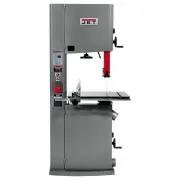
6 3.0 About this manual This manual is provided by JET, covering the safe operation and maintenance procedures for a JET Model VBS- 18MWEVS Band Saw. This manual contains instructions on installation, safety precautions, general operating procedures, maintenance instructions and parts breakdown. You...
Page 8 - Overall Dimensions
8 1 Subject to local/national electrical codes. 2 The specified values are emission levels and are not necessarily to be seen as safe operating levels. As workplace conditions vary, this information is intended to allow the user to make a better estimation of the hazards and risks involved only. 4.1...
Page 9 - Tools required for assembly
9 5.0 Setup and Assembly Read and understand the entire contents of this manual before attempting assembly or operation. Failure to comply may cause serious injury. 5.1 Shipping contents Refer to Figure 5-1A and 5-1B. 1 Band saw (not shown) 1 Fence body – A 1 Resaw fence – B 1 Table – C 1 Table inse...
Page 10 - Installing and aligning table; Installing guide rail
10 5.6 Installing and aligning table Table is heavy. Mounting with the help of another person is recommended. Refer to Figures 5-3 through 5-4: 1. Slide table so that saw blade passes through slot (A). 2. Line up table to trunnions and insert four hex cap screws with lock washers and flat washers (F...
Page 11 - Electrical connections; GROUNDING INSTRUCTIONS; Single phase connections
11 Figure 5-7 5.9 Miter gauge Refer to Figure 5-8. 1. Slide miter gauge into table slot. 2. Use a square to verify that miter gauge face is square to blade. 3. If miter gauge is not square to blade, loosen lock knob (H 1 , Figure 5-8) and adjust to proper setting. Tighten lock knob. 4. If pointer is...
Page 12 - Circuit Information; Aluminum resaw fence
12 6.3 Circuit Information The Band Saw should be connected to a dedicated circuit with a circuit breaker or time delay fuse rated “D” with the appropriate amperage rating. See Table 1 for recommended circuit sizes. Local codes take precedence over recommendations. Model Voltage Recommended Circuit*...
Page 13 - Leveling table insert
13 7.4 Adjusting 90-degree table stop Before adjusting the 90º table stop, the blade tension must be properly adjusted (see sect. 7.7) To adjust 90º table stop: 1. Loosen lock handle (D, Figure 7-4) and use knob (E) to tilt table until it rests against table stop bolt (F, not visible). Retighten loc...
Page 14 - Adjusting blade tension lever
14 Figure 7-8 11. Position blade at center of upper and lower wheels. 12. Reinstall dust block (J, Figure 7-8) and table slot handle (HP6, Figure 5-3). 13. Before operating band saw, the new blade must be tensioned and tracked, in that order. Find instructions for tensioning and tracking the blade i...
Page 17 - Guide post parallelism; Replacement, and Tensioning
17 Figure 7-17 Figure 7-18 7.14 Guide post Refer to Figure 7-19. 1. Disconnect band saw from power source. 2. Loosen lock knob (L) and raise or lower guide post using handwheel (M). Figure 7-19 3. Position blade guide assembly so that bottom of guide bearings are about 1/8” above material to be cut....
Page 19 - Operating Controls
19 9. Tighten the lock handle to hold the motor in the down position when tension is correct. 10. When complete, the belt routing will match Figure 7.20. 11. Complete the change to “Wood Mode” by installing the correct blade and changing the display to Wood Mode. 7.17.2 Changing to “Metal cutting” M...
Page 20 - Setting Speed Digital Readout; Variable Speed Control Dial
20 NOTE: When the key switch is turned Off, it is common and normal for the display to show an LV (Low Voltage) code. Additionally, when the key switch is turned Off, please wait 10 – 15 seconds before turning the key switch back On. The display will show an LV-C (Low Voltage Fluctuation) code. 8.2 ...
Page 22 - Operation – Metal; General Procedure; Blade Selection Guide
22 Figure 9-5 10.0 Operation – Metal Consult section 8.0 for identification of the controls. Never operate band saw without blade and wheel covers in place and secured. The following section contains basic information and is not intended to cover all possible applications or techniques using the ban...
Page 24 - Blade breakage
24 Straight Set – used for free cutting non-ferrous materials; i.e., aluminum, magnesium, plastics, and wood. Wavy Set – used on materials of varying thickness (pipe, tubing, and structural shapes). Raker Set – used in large cuts on thick plate and bar stock where finish of cut is not as important a...
Page 26 - Speed and Pitch Chart – Metal
Page 27 - Typical Band Saw Operations
Page 28 - Lubrication points
28 15.0 User-maintenance Before any intervention on the machine, disconnect it from the electrical supply by pulling out the plug. Failure to comply may cause serious injury. Clean band saw regularly to remove any resinous deposits and sawdust. Keep miter slot, and guide bearings, clean and free of ...
Page 29 - Troubleshooting VBS-18MWEVS Band Saw; Operational problems
29 16.0 Troubleshooting VBS-18MWEVS Band Saw 16.1 Operational problems Table 5 Symptom Probable Cause Correction * Table tilt does not hold position under load. Lock handle not tight. Tighten lock handle. Trunnion locking mechanism is broken or worn. Replace trunnion locking mechanism. Table will no...
Page 31 - Mechanical and electrical problems
31 16.2 Mechanical and electrical problems Table 6 Symptom Probable Cause Correction * Machine will not start/restart or repeatedly trips circuit breaker or blows fuses. No incoming power. Verify machine connections. Cord damaged. Replace cord. Band Saw frequently trips. One cause of overloading tri...
Page 32 - Replacement Parts
32 17.0 Replacement Parts Replacement parts are listed on the following pages. To order parts or reach our service department, call 1-800- 274-6848 Monday through Friday, 8:00 a.m. to 5:00 p.m. CST. Having the Model Number and Serial Number of your machine available when you call will allow us to se...
Page 40 - VBS-18MWEVS Trunnion Support Bracket Assembly – Parts List
40 18.2.2 VBS-18MWEVS Trunnion Support Bracket Assembly – Parts List Index No Part No Description Size Qty JWBS15-1138A ............. Trunnion Support Bracket Assembly (#1 thru 34) ...................................... 1 TS-1550061 .................. Flat Washer .......................................
Page 43 - VBS-18MWEVS Guide Bar Bracket Assembly – Exploded View
43 18.5.1 VBS-18MWEVS Guide Bar Bracket Assembly – Exploded View 18.5.2 VBS-18MWEVS Guide Bar Bracket Assembly – Parts List Index No Part No Description Size Qty JWBS18B-1125 ............. Guide Bar Bracket Assembly (#1 thru 28) ........... ...................................... 1 JWBS18B-1125-401 ....
Page 46 - VBS-18MWEVS Lower Blade Guide Assembly – Exploded View
46 18.8.1 VBS-18MWEVS Lower Blade Guide Assembly – Exploded View 18.8.2 VBS-18MWEVS Lower Blade Guide Assembly – Parts List Index No Part No Description Size Qty JWBS18B-1142 ............. Lower Blade Guide Assembly (#1 thru 12) .......... ...................................... 1 PM1500-096-01 ........
Page 47 - VBS-18MWEVS Upper Blade Guide Assembly – Exploded View
47 18.9.1 VBS-18MWEVS Upper Blade Guide Assembly – Exploded View 18.9.2 VBS-18MWEVS Upper Blade Guide Assembly – Parts List Index No Part No Description Size Qty JWBS18B-1126 ............. Upper Blade Guide Assembly (#1 thru 18) .......... ...................................... 1 PM1500-095-01 ........
Page 50 - Electrical connections for VBS-18MWEVS
Page 51 - Warranty and service
51 20.0 Warranty and service JET warrants every product it sells against manufacturers’ defects. If one of our tools needs service or repair, please contact Technical Service by calling 1-800-274-6846, 8AM to 5PM CST, Monday through Friday. Warranty Period The general warranty lasts for the time per...