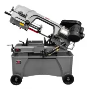
Jet 413451 - Manuals
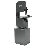
User Manual Jet 413451


Summary
2 1.0 Warranty and Service JET warrants every product it sells against manufacturers’ defects. If one of our tools needs service or repair, please contact Technical Service by calling 1-800-274-6846, 8AM to 5PM CST, Monday through Friday. Warranty Period The general warranty lasts for the time perio...
3 2.0 Table of Contents Section Page 1.0 Warranty and Service ............................................................................................................................................. 2 2.0 Table of Contents .........................................................................
4 3.0 Safety Warnings 1. Read and understand the entire owner’s manual before attempting assembly or operation. 2. Read and understand the warnings posted on the machine and in this manual. Failure to comply with all of these warnings may cause serious injury. 3. Replace the warning labels if they b...
Jet Band Saws Manuals
-
 Jet 413410
User Manual
Jet 413410
User Manual
-
 Jet 413411
User Manual
Jet 413411
User Manual
-
 Jet 413452
User Manual
Jet 413452
User Manual
-
 Jet 414428
User Manual
Jet 414428
User Manual
-
 Jet 414457
User Manual
Jet 414457
User Manual
-
 Jet 414458
User Manual
Jet 414458
User Manual
-
 Jet 414466
User Manual
Jet 414466
User Manual
-
 Jet 414468
User Manual
Jet 414468
User Manual
-
 Jet 414471
User Manual
Jet 414471
User Manual
-
 Jet 414472
User Manual
Jet 414472
User Manual
-
 Jet 414478
User Manual
Jet 414478
User Manual
-
 Jet 414479
User Manual
Jet 414479
User Manual
-
 Jet 414483
User Manual
Jet 414483
User Manual
-
 Jet 414500
User Manual
Jet 414500
User Manual
-
 Jet 414502
User Manual
Jet 414502
User Manual
-
 Jet 414548
User Manual
Jet 414548
User Manual
-
 Jet 414558
User Manual
Jet 414558
User Manual
-
 Jet 414559
User Manual
Jet 414559
User Manual
-
 Jet 414560
User Manual
Jet 414560
User Manual
-
 Jet 415559
User Manual
Jet 415559
User Manual