Page 2 - SYMBOLS; English
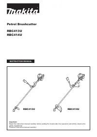
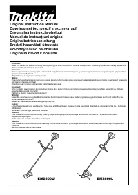
Thank you very much for selecting the MAKITA brushcutter. We are pleased to be able to offer you the MAKITA brushcutter which is the result of a long development programme and many years of knowledge and experience. Please read, understand and follow this booklet which refers in detail to the variou...
Page 3 - SAFETY INSTRUCTIONS; General Instructions; Intended use of the machine; Starting up the brushcutter
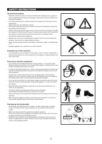
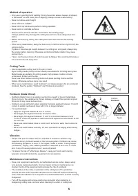
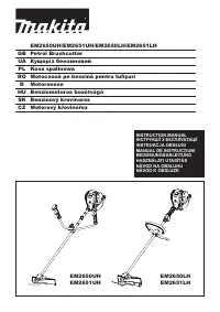
(1) (3) (2) (4) (5) (6) 15m(50 FT ) 360 SAFETY INSTRUCTIONS 3 General Instructions Read this instruction manual to become familiar with handling of the equipment. – Users insufficiently informed will risk danger to themselves as well as others due to improper handling.It is recommended only to lend ...
Page 4 - Refuelling
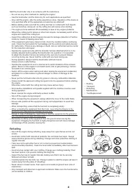
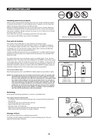
Resting • Transport • Refuelling • Maintenance • Tool Replacement • 3 meters (10 ft) 4 Start the brushcutter only in accordance with the instructions. Do not use any other methods for starting the engine! – Use the brushcutter and the tools only for such applications as specified. – Only start the e...
Page 5 - Method of operation
12 2 Caution: Kickback Diagrammatic figure Diagrammatic figure 5 Method of operation Only use in good light and visibility. During the winter season beware of slippery – or wet areas, ice and snow (risk of slipping). Always ensure a safe footing.Never cut above waist height. – Never stand on a ladde...
Page 7 - TECHNICAL DATA
Model RBC413U RBC414U Handle type U handle Dimensions: length x width x height (without cutting blade) mm 1,710 x 650 x 435 1,710 x 630 x 515 Net weight (without plastic guard and cutting blade) kg 7.1 7.2 Volume (fuel tank) cm 3 1,100 Engine displacement cm 3 40.2 Maximum engine performance kW 1.47...
Page 8 - DESIGNATION OF PARTS
DESIGNATION OF PARTS 19 12 13 20 15 16 18 17 14 1 2 8 9 10 7 3 11 4 5 6 1 2 8 9 10 7 3 11 4 5 6 RBC413U RBC414U No. DESIGNATION OF PARTS 1 Fuel tank 2 Clutch case 3 Hanger 4 I-O switch (on/off) 5 Throttle lever 6 Throttle wire 7 Handle 8 Handle holder 9 Shaft 10 Cutting tool guard (Protector) 11 Gea...
Page 9 - ASSEMBLY OF ENGINE AND SHAFT
(2) (1) CAUTION: Before doing any work on the brushcutter, always switch off the motor and pull the spark plug connector off the spark plug. Always wear protective gloves. CAUTION: Start the brushcutter only after having assembled it completely. After checking the parts, fasten the drive shaft to th...
Page 10 - Be sure to use genuine MAKITA cutter blades or; MOUNTING OF PROTECTOR
For model RBC413U, RBC414U – After assembling the handle, fit the control cable to the shaft by two clips (1). Clips (1) To meet the applicable safety provisions, only the tool/protector combinations as indicated in the table must be used. Be sure to use genuine MAKITA cutter blades or nylon cutting...
Page 12 - MOUNTING OF CUTTER BLADE OR NYLON CUTTING HEAD
(4) (3) (2) (1) (4) Insert the hex wrench through the hole in the gear case and rotate the receiver – washer (4) until it is locked with the hex wrench. Loosen the nut (1) (left-hand thread) with the socket wrench and remove the nut – (1), cup (2), and clamp washer (3). Turn the machine upside down,...
Page 13 - Storage of Fuel
Handling petroleum products Utmost care is required when handling fuel. Fuel may contain substances similar to solvents. Refuel either in a well ventilated area or outdoors. Do not inhale fuel vapors, avoid any contact of fuel or oil with your skin. Mineral oil products degrease your skin. If your s...
Page 14 - CORRECT HANDLING OF MACHINE; Detachment
Detachment In case of emergency, remove the emergency detachment lever (1) by pulling – strongly with a finger. The machine sill detach from body. Be extremely careful to maintain control of the machine at this time. Do not allow the machine to be deflected toward you or anyone in the work vicinity....
Page 15 - PUTTING INTO OPERATION
(3) (1) (2) (4) (5) Starting Move at least 3m (10ft) away from the place of refuelling. Place the brushcutter on a clean piece of ground taking care that the cutting tool does not come into contact with the ground or any other objects. First place the machine on the ground. – Give a gentle push on t...
Page 16 - IDLE ADJUSTMENT; Checking the Idle speed; RESHARPENING THE CUTTING TOOL; Stopping; OPERATION OF THROTTLE LEVER
IDLE ADJUSTMENT Never attempt to make engine adjustments while the unit is running and strapped – to the operator. Always make engine adjustments with the unit resting on a flat, clear surface. The cutter blade or the nylon cutting head should not run when the control lever is fully released. If nec...
Page 20 - MAINTENANCE SCHEDULE
(3) (4) 1. Before operation, pay particular attention to the tightness of Cutter Blade or nylon cutting head. Check bolts and nuts and retighten if necessary.: Every 8 hour (Daily) 2. Check clogging of the cooling air passage and the cylinder fins. Clean them if necessary.: Every 8 hours (Daily) 3. C...
Page 21 - Fault location; STORAGE
When the machine is in storage for a long time, drain fuel from the fuel tank and – carburetor, as follows: Drain all fuel from the fuel tank. Dispose of properly and in accordance with all local laws. Remove the spark plug and a few drops of oil into the spark plug hole. Then, pull – the starter ge...
Page 22 - TROUBLESHOOTING
TROUBLESHOOTING Before making a request for repairs, check a trouble for yourself. If any abnormality is found, control your machine according to the description of this manual. Never tamper or dismount any part contrary to the description. For repairs, contact Authorized Service Agent or local deal...
Page 24 - Makita Corporation