Makita EM4351UH - Manuals
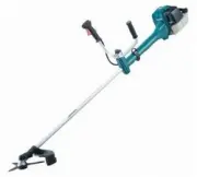
Manual Makita EM4351UH


Summary
CAUTION: Repair the machine in accordance with “Instruction manual” or “Safety instructions”. [4] DISASSEMBLY/ASSEMBLY [4]-1. Warning Follow the instructions described below in advance before repairing: • Wear gloves. • Remove the cutting tool from the unit, and if it is a saw blade, attach the blad...
[4] DISASSEMBLY/ASSEMBLY [4]-2. Engine and Shaft R epair P 3 / 2 2 (1) Press down the tab of Cleaner plate assembly gently and separate Cleaner cover assembly from Cleaner plate assembly by loosening M5x20 Hex socket head bolt. ( Fig. 1 ) (2) Loosen 5x16 Tapping screw and loosen Clamp that holds Bul...
[4] DISASSEMBLY/ASSEMBLY [4]-7. Ignition system R epair P 1 1 / 2 2 (1) Remove Plug cap from Spark plug, then check the continuity between Plug cap spring and the ground (earth) terminal of Ignition coil with a circuit tester. If there is normal continuity, the resistance value will be 2.0 kΩ± 0.5 k...
Makita Grass Trimmers Manuals
-
 Makita DUR181RF
User Manual
Makita DUR181RF
User Manual
-
 Makita DUR181Z
User Manual
Makita DUR181Z
User Manual
-
 Makita DUR189Z
User Manual
Makita DUR189Z
User Manual
-
 Makita DUR190LZX3
User Manual
Makita DUR190LZX3
User Manual
-
 Makita DUR190UZX3
User Manual
Makita DUR190UZX3
User Manual
-
 Makita DUR192LZ
User Manual
Makita DUR192LZ
User Manual
-
 Makita DUR369LZ
User Manual
Makita DUR369LZ
User Manual
-
 Makita EM2600U
User Manual
Makita EM2600U
User Manual
-
 Makita EM2651UH
User Manual
Makita EM2651UH
User Manual
-
 Makita EM4350RH
User Manual
Makita EM4350RH
User Manual
-
 Makita GRU01M1
User Manual
Makita GRU01M1
User Manual
-
 Makita LXT DUR189Z
User Manual
Makita LXT DUR189Z
User Manual
-
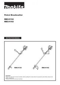 Makita RBC413U
User Manual
Makita RBC413U
User Manual
-
Makita RBC414U
User Manual
-
 Makita UR100DWAEX
User Manual
Makita UR100DWAEX
User Manual
-
 Makita UR2300
User Manual
Makita UR2300
User Manual
-
 Makita UR3000
User Manual
Makita UR3000
User Manual
-
 Makita UR3502
User Manual
Makita UR3502
User Manual
-
 Makita XRU02Z
User Manual
Makita XRU02Z
User Manual
-
 Makita XRU15PT
User Manual
Makita XRU15PT
User Manual