Page 2 - SYMBOLS; English
β Thank you very much for purchasing the εAKITA τutdoor Power Equipmentέ We are pleased to recommend to you the εAKITA product which is the result of a long development program and many years of knowledge and experienceέ Please read this booklet which refers in detail to the various points that will...
Page 3 - SAFETY INSTRUCTIONS; General Instructions
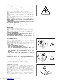
γ 15 meters Diagrammatic igure SAFETY INSTRUCTIONS General Instructions ● Read this instruction manual to become familiar with handling of the equipmentέ Users insuficiently informed will risk danger to themselves as well as others due to improper handlingέ ● It is recommended only to lend the equip...
Page 4 - Refuelling
ζ Start the brushcutter only in accordance with the instructionsέ ● Do not use any other methods for starting the engine! ● Use the brushcutter and the tools only for such applications as speciiedέ ● τnly start the engine, after the entire assembly is doneέ τperation of the device is only permitted ...
Page 6 - For European countries only; EC Declaration of Conformity; εakita declares that the following machine(s)μ; Never straighten or weld damaged cutting tools.
θ For European countries only EC Declaration of Conformity εakita declares that the following machine(s)μ Designation of εachineμ Petrol Backpack Brushcutter εodel σoέή Typeμ EεζγηίRώ Conforms to the following European Directivesμ βίίίή1ζήEC, βίίθήζβήEC They are manufactured in accordance with the f...
Page 7 - TECHNICAL DATA
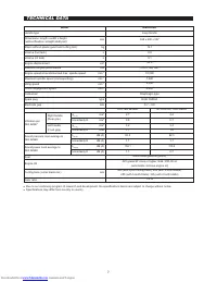
ι TECHNICAL DATA εodel Eε4350RH ώandle type δoop handle Dimensionsμ length x width x height (without lexible ή straight shaft part) mm γηκ x βκί x ηκι εass (without plastic guard and cutting tool) kg 1βέ1 Volume (fuel tank) δ ίέκ Volume (oil tank) δ ίέ1 Engine displacement cm γ ζγέί εaximum engine p...
Page 8 - DESIGNATION OF PARTS
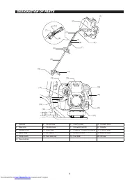
κ DESIGNATION OF PARTS (1) (2) (3) (5) (7) (6) (8) (9) (10) (11) (4) (6) (7) (12) (13) (14) (15) (16) (17) (18) (19) (20) (21) 1έ ώarness βέ Clutch case γέ Control cable ζέ όlexible shaft ηέ Rear grip θέ Throttle lever ιέ Iάτ switch (onήoff) κέ ώandle λέ Straight shaft 1ίέ ύear case 11έ Protector (C...
Page 9 - MOUNTING OF HANDLE
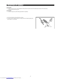
λ CAUTIONμ ● Before doing any work on the equipment, always stop the engine and pull the spark plug connector off the spark plugέ ● Always wear protective gloves! CAUTIONμ ● Start the engine only after having assembled it completelyέ MOUNTING OF HANDLE ● όix the loop handle on the shaft with two scr...
Page 10 - εounting the lexible shaft; MOUNTING OF FLEXIBLE SHAFT; Connecting the control cable
1ί εounting the lexible shaft 1έ Remove the bolt (1) from the end of the straight shaft (β)έβέ Remove the cap from the lexible shaftέ NOTEμ ● Do not lose the capέ Always put the cap when removing the lexible shaftέ γέ Turn the lexible shaft so that the dented part (γ) of the lexible shaft faces down...
Page 11 - MOUNTING OF PROTECTOR; For metal blades
11 To meet the applicable safety provisions, only the toolήprotector combinations as indicated in the table must be usedέ MOUNTING OF PROTECTOR CAUTIONμ ● The appropriate protector must always be installed, for your own safety and in order to comply with accident prevention regulationsέ τperation of...
Page 12 - For nylon cutting head
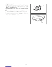
1β For nylon cutting head ● Be sure to mount the nylon cutting head protector (1ί) onto the type A metal blade protector (γ) assembled with the nylon cutting head protectorέ ● εount the nylon cutting head protector (1ί) by sliding it into place from the lank of the metal blade protector (γ)έ ● Remov...
Page 13 - Be sure to use genuine εAKITA metal blades or nylon; MOUNTING OF METAL BLADE OR NYLON CUTTING HEAD; εounting of metal blade with the hex wrench still in place; εounting of nylon cutting head
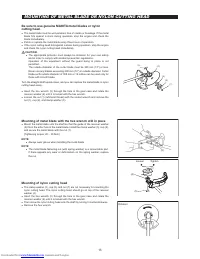
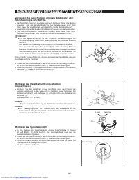
1γ Be sure to use genuine εAKITA metal blades or nylon cutting head. ● The metal blade must be well polished, free of cracks or breakageέ If the metal blade hits against a stone during operation, stop the engine and check the blade immediatelyέ ● Polish or replace the metal blade every three hours o...
Page 14 - Inspection and reill of engine oil; BEFORE START OF OPERATION; Replacement of oilμ “Oil cap”
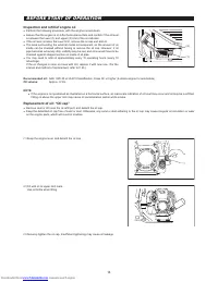
1ζ Inspection and reill of engine oil ● Perform the following procedure, with the engine cooled downέ ● Assure that the engine is on a lat horizontal surface and conirm if the oil level is between the lower (1) and upper (β) limit of the oil indicatorέ ● If the oil level is below the lower limit, re...
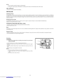
Page 15 - REFUELLING
1η Refuelling WARNINGμ ● Shut off the engine before refuelling, keep away from open lames and do not smoke. ● δoosen the tank cap (1) a little to release the tank pressureέ ● Remove the tank cap, and refuelέ Dτ στT ill fuel more than fuel upper limit (γ)έ ● Wipe the outside of the tank cap to preven...
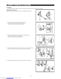
Page 16 - CORRECT HANDLING OF MACHINE; Attachment of harness
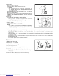
1θ CORRECT HANDLING OF MACHINE WARNINGμ ● όailure to maintain complete control of the machine at all could result in serious bodily injury or DEATώέ (5) (6) A B (2) (1) Attachment of harness Adjust the harness for shouldering the engine comfortably during operationέ 1έ Put the harness on your back, ...
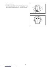
Page 17 - Releasing the machine
1ι Releasing the machine ● To release the machine, squeeze the sides of the buckle (1) and take off the harnessέ Be extremely careful to maintain control of the machine at this timeέ Do not allow the machine to be delected toward you or anyone in the work vicinityέ (1) Downloaded from www.Manualslib...
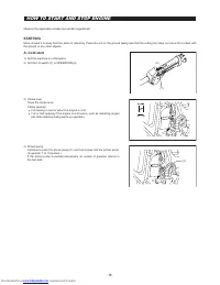
Page 18 - HOW TO START AND STOP ENGINE
1κ τbserve the applicable accident prevention regulations! STARTING εove at least γ m away from the place of refuellingέ Place the unit on the ground taking care that the cutting tool does not come into contact with the ground or any other objectsέ Aμ Cold start 1) Set this machine on a lat spaceέβ)...
Page 19 - Bμ Warm start
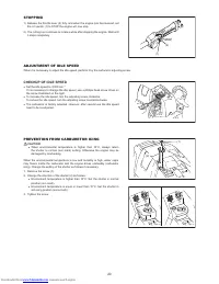
1λ NOTEμ ● Do not pull the throttle lever unnecessarily when the engine is not runningέ It may cause looding of fuel in the engine, and may cause the engine dificult to start upέ ● In case of looding of the fuel, remove the spark plug and pull the starter handle slowly to remove excess fuelέ Also, d...
Page 20 - CHECKUP OF IDδE SPEED; STOPPING
βί ADJUSTMENT OF IDLE SPEED When it is necessary to adjust the idle speed, perform it by the carburetor adjusting screwέ CHECKUP OF IDδE SPEED ● Set the idle speed to γ,ίίί min –1 έ If it is necessary to change the idle speed, use a phillips head screw driver on the screw illustrated on the rightέ ●...
Page 21 - RESHARPENING THE CUTTING TOOL; NYδON CUTTING HEAD
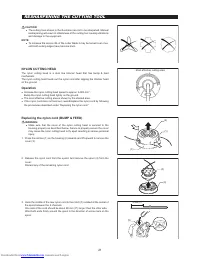
β1 Replacing the nylon cord (BUεP & FEED) WARNINGμ ● εake sure that the cover of the nylon cutting head is secured to the housing properly as described belowέ όailure to properly secure the cover may cause the nylon cutting head to ly apart resulting in serious personal injuryέ 1έ Press the latc...
Page 22 - ββ
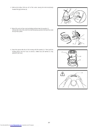
ββ ηέ εount the spool in the cover as holding notches meet the eyelets (ι)έ Unhook the ends of the cord from their temporary position and feed the cords through the eyeletsέ ζέ Wind all but about 1ίί mm (ζ") of the cords, leaving the ends temporarily hooked through notches (θ)έ (6) (7) (8) (7) (...
Page 23 - βγ; Daily checkup and maintenance; SERVICING INSTRUCTIONS; REPδACEεENT OF ENGINE OIδ
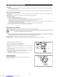
βγ CAUTIONμ ● Before doing any work on the equipment, always stop the engine and pull the plug cap off the spark plug (see “checking the spark plug”)έ Always wear protective gloves! To ensure a long service life and to avoid any damage to the equipment, the following servicing operations should be p...
Page 24 - Removing air cleaner cover; NOTICEμ
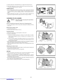
βζ η) Set the engine level, and gradually ill up to upper limit mark with new oilέθ) After illing, tightly secure oil cap, so that it will not loosen and cause leaksέ If oil cap is not tightly secured, it may leakέ CLEANING OF AIR CLEANER WARNINGμ Shut off the engine, keep away from open lames and d...
Page 25 - SUPPLY OF GREASE TO GEAR CASE
βη CHECKING THE SPARK PLUG ● τnly use the supplied universal wrench to remove or to install the spark plugέ ● The gap between the two electrodes of the spark plug should be ίέι – ίέκ mm (ίέίβκ" – ίέίγβ")έ If the gap is too wide or too narrow, adjust itέ If the spark plug is clogged or contam...
Page 26 - WARNINGμ INFδAεεABδES STRICTδY PROHIBITED; REPLACEMENT OF FUEL PIPE; CAUTIONμ INFδAεεABδES STRICTδY PROHIBITED; INSPECTION OF BOLTS, NUTS AND SCREWS
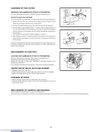
βθ CLEANING OF FUEL FILTER WARNINGμ INFδAεεABδES STRICTδY PROHIBITED Interval of Cleaning and Inspectionμ εonthly (every ηί operating hours) Suction head in the fuel tank Check the fuel ilter (1) periodicallyέ To check the fuel ilter, follow the steps belowμ1έ Remove the fuel tank cap, drain the fue...
Page 27 - βι; STORAGE; Attention after long-time storage
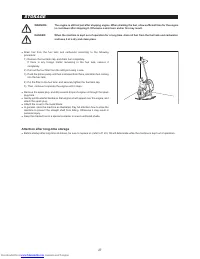
βι WARNINGμ The engine is still hot just after stopping engine. When draining the fuel, allow suficient time for the engine to cool down after stopping it. Otherwise a skin burn and/or ire may result. DANGERμ When the machine is kept out of operation for a long time, drain all fuel from the fuel tan...
Page 28 - βκ
βκ Operating time Item Before operation After refulelling Daily (10h) 25h 50h 200h Before storage Corres- ponding P Engine oil Inspect 1ζ Replace * 1 βγ Tightening parts(bolt, nut) Inspect βθ όuel tank Cleanήinspect — Drain fuel * γ βι Throttle lever Check function — Stop switch Check function βγ Cu...
Page 29 - βλ; TROUBLESHOOTING
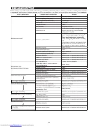
βλ TROUBLESHOOTING Before making a request for repairs, check for trouble by yourselfέ If any abnormality is found, control your machine according to the description of this manualέ σever tamper or dismount any part contrary to the descriptionέ όor repairs, contact Authorized Service Agent or local ...
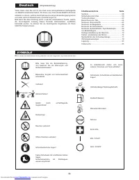
Page 30 - SYMBOLE; Deutsch
58 Vielen Dank, dass Sie sich für den Kauf eines motorgetriebenen Gartengeräts von MAKITA entschieden haben. Wir freuen uns, Ihnen dieses MAKITA-Produkts anbieten zu können, welches das Ergebnis eines langen Entwicklungsprogramms und vieler Jahre an Erkenntnissen und Erfahrungen ist. Bitte lesen Sie...
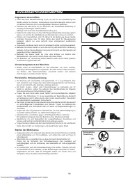
Page 31 - SICHERHEITSVORSCHRIFTEN; Allgemeine Vorschriften
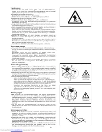
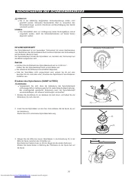
59 15 Meter Schematische Darstellung SICHERHEITSVORSCHRIFTEN Allgemeine Vorschriften ● Lesen Sie diese Betriebsanleitung durch, um sich mit der Handhabung des Geräts vertraut zu machen. Unzureichend informierte Benutzer können sich und andere Personen durch unsachgemäßen Gebrauch gefährden. ● Verlei...
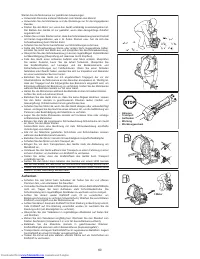
Page 32 - Auftanken
60 Starten Sie die Motorsense nur gemäß den Anweisungen. ● Verwenden Sie keine anderen Methoden zum Starten des Motors! ● Verwenden Sie die Motorsense und die Werkzeuge nur für die angegebenen Zwecke. ● Starten Sie den Motor nur, wenn das Gerät vollständig zusammengebaut ist. Der Betrieb des Geräts ...
Page 34 - Nur für europäische Länder; EG-Konformitätserklärung; Beschädigte Schneidwerkzeuge dürfen auf keinen Fall
62 Nur für europäische Länder EG-Konformitätserklärung Makita erklärt, dass die folgende(n) Maschine(n): Bezeichnung der Maschine: Rückentragbare Benzin-Motorsense Modell-Nr./Typ: EM4350RH den folgenden EU-Richtlinien genügt / genügen: 2000/14/EG, 2006/42/EG Sie werden gemäß den folgenden Standards ...
Page 35 - TECHNISCHE DATEN
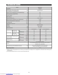
63 TECHNISCHE DATEN Modell EM4350RH Handgrifftyp Bügelgriff Abmessungen: Länge x Breite x Höhe (ohne Biegewellen- / Geradwellenteil) mm 358 x 280 x 587 Gewicht (ohne Kunststoffschutz und Schneidwerkzeug) kg 12,1 Fassungsvermögen (Kraftstofftank) L 0,8 Volumen (Öltank) L 0,1 Motor-Hubraum cm 3 43,0 M...
Page 36 - BEZEICHNUNG DER TEILE
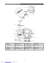
64 BEZEICHNUNG DER TEILE (1) (2) (3) (5) (7) (6) (8) (9) (10) (11) (4) (6) (7) (12) (13) (14) (15) (16) (17) (18) (19) (20) (21) 1. Tragegurt 2. Kupplungsgehäuse 3. Steuerkabel 4. Biegewelle 5. Hinterer Griff 6. Gashebel 7. I-O-Schalter (ein/aus) 8. Handgriff 9. Gerade Welle 10. Getriebegehäuse 11. ...
Page 37 - MONTIEREN DES HANDGRIFFS
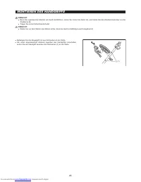
65 VORSICHT: ● Bevor Sie irgendwelche Arbeiten am Gerät durchführen, stellen Sie immer den Motor ab, und ziehen Sie den Zündkerzenstecker von der Zündkerze ab. ● Tragen Sie immer Schutzhandschuhe! VORSICHT: ● Stellen Sie vor dem Starten des Motors sicher, dass das Gerät vollständig zusammengebaut is...
Page 38 - Montieren der Biegewelle; MONTIEREN DER BIEGEWELLE; Anschließen des Steuerkabels
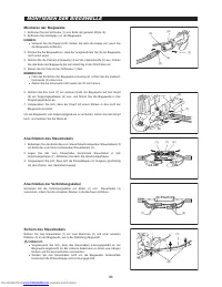
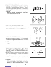
66 Montieren der Biegewelle 1. Entfernen Sie die Schraube (1) vom Ende der geraden Welle (2).2. Entfernen Sie die Kappe von der Biegewelle. HINWEIS: ● Verlieren Sie die Kappe nicht. Setzen Sie stets die Kappe auf, wenn Sie die Biegewelle entfernen. 3. Drehen Sie die Biegewelle so, dass der ausgebuch...
Page 39 - MONTIEREN DER SCHUTZHAUBE; Für Metallblätter
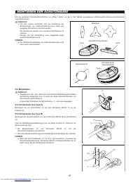
67 Um die geltenden Sicherheitsvorschriften zu erfüllen, dürfen nur die in der Tabelle angegebenen Werkzeug/Schutzhaube-Kombinationen verwendet werden. MONTIEREN DER SCHUTZHAUBE VORSICHT: ● Für Ihre eigene Sicherheit und die Einhaltung der Bestimmungen zur Unfallverhinderung muss stets eine geeignet...
Page 40 - Für Nylonfadenkopf
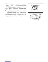
68 Für Nylonfadenkopf ● Montieren Sie die Nylonfadenkopf-Schutzhaube (10) an der Metallblatt- Schutzhaube (3) des Typs A, die mit der Nylonfadenkopf-Schutzhaube kombiniert wird. ● Montieren Sie die Nylonfadenkopf-Schutzhaube (10), indem Sie sie von der Flanke der Metallblatt-Schutzhaube (3) aus hine...
Page 41 - MONTIEREN DES METALLBLATTS / NYLONFADENKOPFS; Montieren des Metallblatts mit eingestecktem
69 (4) (5) Verwenden Sie ausschließlich originale Metallblätter oder Nylonfadenköpfe von MAKITA. ● Das Metallblatt muss gut geschliffen sein und darf keine Risse oder Brüche aufweisen. Falls das Metallblatt während des Betriebs gegen einen Stein stößt, stellen Sie den Motor ab, und überprüfen Sie da...
Page 42 - Überprüfen und Nachfüllen von Motoröl; VOR BETRIEBSBEGINN; Ölwechsel: „Öldeckel“
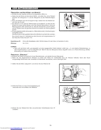
70 Überprüfen und Nachfüllen von Motoröl ● Wenden Sie das folgende Verfahren bei abgekühltem Motor an. ● Stellen Sie den Motor auf eine ebene Fläche, und prüfen Sie, ob der Ölstand zwischen der Untergrenze (1) und der Obergrenze (2) des Ölstandanzeigers liegt. ● Wenn der Ölstand unter der Untergrenz...
Page 43 - AUFTANKEN
71 Auftanken WARNUNG: ● Schalten Sie den Motor vor dem Auftanken aus, halten Sie ihn von offenen Flammen fern, und rauchen Sie während des Auftankens nicht. ● Lösen Sie den Tankdeckel (1) ein wenig, um den Tankdruck abzulassen. ● Nehmen Sie den Tankdeckel ab, und tanken Sie auf. Füllen Sie Kraftstof...
Page 44 - RICHTIGE HANDHABUNG DER MASCHINE; Anbringung des Tragegurts
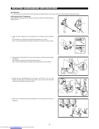
72 RICHTIGE HANDHABUNG DER MASCHINE WARNUNG: ● Ein Verlust der vollkommenen Kontrolle über die Maschine kann zu schweren oder gar TÖDLICHEN Verletzungen führen. (5) (6) A B (2) (1) Anbringung des Tragegurts Stellen Sie den Tragegurt so ein, dass Sie den Motor während der Arbeit bequem tragen können....
Page 45 - Ablegen der Maschine
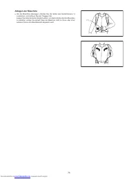
73 Ablegen der Maschine ● Um die Maschine abzulegen, drücken Sie die Seiten des Gurtschlosses (1) zusammen, und nehmen Sie den Tragegurt ab. Lassen Sie dabei äußerste Sorgfalt walten, um die Kontrolle über die Maschine zu behalten. Achten Sie darauf, dass die Maschine nicht zu Ihnen oder einer ander...
Page 46 - STARTEN; STARTEN UND ABSTELLEN DES MOTORS
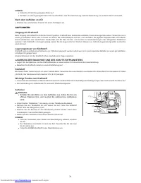
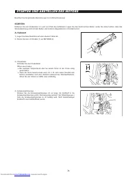
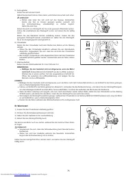
74 Beachten Sie die geltenden Bestimmungen zur Unfallverhinderung! STARTEN Entfernen Sie sich mindestens 3 m weit vom Platz des Auftankens. Legen Sie das Gerät auf den Boden, wobei Sie darauf achten, dass das Schneidwerkzeug nicht mit dem Boden oder anderen Gegenständen in Kontakt kommt. A: Kaltstar...
Page 48 - EINSTELLEN DER LEERLAUFDREHZAHL; ÜBERPRÜFEN DER LEERLAUFDREHZAHL; ABSTELLEN
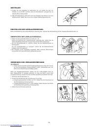
76 EINSTELLEN DER LEERLAUFDREHZAHL Sollte eine Einstellung der Leerlaufdrehzahl notwendig sein, nehmen Sie die Einstellung mit der Vergaser-Einstellschraube vor. ÜBERPRÜFEN DER LEERLAUFDREHZAHL ● Stellen Sie die Leerlaufdrehzahl auf 3.000 min –1 ein. Sollte eine Änderung der Leerlaufdrehzahl notwend...
Page 49 - NACHSCHÄRFEN DES SCHNEIDWERKZEUGS; NYLONFADENKOPF
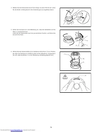
77 Ersetzen des Nylonfadens (BUMP & FEED) WARNUNG: ● Vergewissern Sie sich, dass die Abdeckung des Nylonfadenkopfs ordnungsgemäß am Gehäuse gesichert ist (siehe folgende Beschreibung). Bei unsachgemäß gesicherter Abdeckung kann der Nylonfadenkopf auseinanderliegen und schwere Verletzungen verurs...
Page 51 - Tägliche Kontrollen und Wartungsarbeiten; WARTUNGSANWEISUNGEN; WECHSELN DES MOTORÖLS
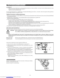
79 VORSICHT: ● Stellen Sie immer den Motor ab, bevor Sie irgendwelche Arbeiten am Gerät durchführen, und ziehen Sie den Zündkerzenstecker von der Zündkerze ab (siehe „Überprüfen der Zündkerze“). Tragen Sie immer Schutzhandschuhe! Um eine lange Nutzungsdauer zu gewährleisten und mögliche Beschädigung...
Page 52 - REINIGEN DES LUFTFILTERS; Entfernen der Luftilterabdeckung; WICHTIGE PUNKTE ZUM ÖL
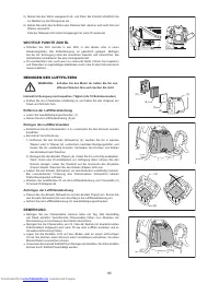
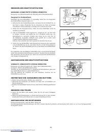
80 5) Stellen Sie den Motor waagerecht ab, und füllen Sie Frischöl allmählich bis zur Markierung der Obergrenze ein. 6) Ziehen Sie nach dem Auffüllen den Öldeckel fest, damit er sich nicht löst und Öllecks verursacht. Falls der Öldeckel nicht sicher festgezogen ist, kann Öl auslaufen. REINIGEN DES L...
Page 53 - ÜBERPRÜFEN DER ZÜNDKERZE; ABSCHMIEREN DES GETRIEBEGEHÄUSES
81 ÜBERPRÜFEN DER ZÜNDKERZE ● Verwenden Sie nur den mitgelieferten Universalschlüssel, um die Zündkerze aus- und einzubauen. ● Der Abstand zwischen den Elektroden der Zündkerze muss 0,7 – 0,8 mm betragen. Falls der Elektrodenabstand zu klein oder zu groß ist, korrigieren Sie ihn. Falls die Zündkerze...
Page 54 - REINIGEN DES KRAFTSTOFFFILTERS; WARNUNG: ZÜNDSTOFFE STRENG VERBOTEN; AUSTAUSCHEN DER KRAFTSTOFFLEITUNG; VORSICHT: ZÜNDSTOFFE STRENG VERBOTEN; INSPEKTION VON SCHRAUBEN UND MUTTERN
82 REINIGEN DES KRAFTSTOFFFILTERS WARNUNG: ZÜNDSTOFFE STRENG VERBOTEN Reinigungs- und Überprüfungsintervall: Monatlich (alle 50 Betriebsstunden) Saugkopf im Kraftstofftank Überprüfen Sie den Kraftstoffilter (1) regelmäßig. Gehen Sie zum Überprüfen des Kraftstoffilters folgendermaßen vor.1. Entfernen...
Page 55 - LAGERUNG; Maßnahmen nach längerer Lagerung
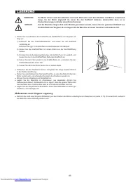
83 WARNUNG: Der Motor ist kurz nach dem Abstellen noch heiß. Warten Sie nach dem Abstellen des Motors ausreichend lange, bis der Motor abgekühlt ist, bevor Sie den Kraftstoff ablassen. Anderenfalls kann es zu Hautverbrennungen und/oder einem Brand kommen. GEFAHR: Soll die Maschine längere Zeit außer...
Page 57 - FEHLERSUCHE
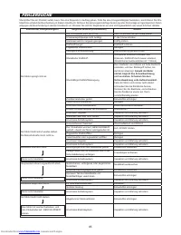
85 FEHLERSUCHE Überprüfen Sie ein Problem selbst, bevor Sie eine Reparatur in Auftrag geben. Falls Sie eine Unregelmäßigkeit feststellen, kontrollieren Sie Ihre Maschine anhand der Beschreibung in diesem Handbuch. Nehmen Sie keine eigenmächtige Änderung oder Demontage an irgendwelchen Teilen entgege...
Page 58 - Makita
885379B995 IDE Makita Jan-Baptist Vinkstraat 2, 3070, Belgium Makita Corporation Anjo, Aichi, Japan www.makita.com Downloaded from www.Manualslib.com manuals search engine


 Makita DUR181RF
User Manual
Makita DUR181RF
User Manual
 Makita DUR181Z
User Manual
Makita DUR181Z
User Manual
 Makita DUR189Z
User Manual
Makita DUR189Z
User Manual
 Makita DUR190LZX3
User Manual
Makita DUR190LZX3
User Manual
 Makita DUR190UZX3
User Manual
Makita DUR190UZX3
User Manual
 Makita DUR192LZ
User Manual
Makita DUR192LZ
User Manual
 Makita DUR369LZ
User Manual
Makita DUR369LZ
User Manual
 Makita EM2600U
User Manual
Makita EM2600U
User Manual
 Makita EM2651UH
User Manual
Makita EM2651UH
User Manual
 Makita GRU01M1
User Manual
Makita GRU01M1
User Manual
 Makita LXT DUR189Z
User Manual
Makita LXT DUR189Z
User Manual
 Makita RBC413U
User Manual
Makita RBC413U
User Manual
 Makita UR100DWAEX
User Manual
Makita UR100DWAEX
User Manual
 Makita UR2300
User Manual
Makita UR2300
User Manual
 Makita UR3000
User Manual
Makita UR3000
User Manual
 Makita UR3502
User Manual
Makita UR3502
User Manual
 Makita XRU02Z
User Manual
Makita XRU02Z
User Manual
 Makita XRU15PT
User Manual
Makita XRU15PT
User Manual
 Makita XRU15PT1
User Manual
Makita XRU15PT1
User Manual