Husqvarna Automower 405X - Manuals

Husqvarna Automower 405X – User Manual, Quick Guide in PDF format online.
Manuals:
User Manual Husqvarna Automower 405X


Summary
Contents 1 Safety 1.1 Safety definitions................................................... 31.2 General safety instructions....................................31.3 Safety instructions for installation..........................41.4 Safety instructions for operation............................41.5 Sa...
1 Safety 1.1 Safety definitions Warnings, cautions and notes are used to point out specially important parts of the manual. WARNING: Used if there is a risk of injury or death for the operator or bystanders if the instructions in the manual are not obeyed. CAUTION: Used if there is a risk of damage ...
1.7 How to lift and move the product WARNING: The product must be switched off before lifting it. The product is disabled when the indicator lamp on the keypad is not lit. CAUTION: Do not lift the product when it is parked in the charging station. It can damage the charging station and/or the produc...
Quick Guide Husqvarna Automower 405X


Summary
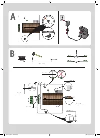
A Colocación y conexión de la estación de carga 1. Coloque la estación de carga en el centro de la zona de trabajo, en una superficie relativamente horizontal y dejando mucho espacio libre delante de la estación de carga. 2. Conecte el cable de baja tensión de la fuente de alimentación a la estación...
A Colocação e ligação da estação de carga 1. Coloque a estação de carga numa posição central na área de trabalho, com muito espaço aberto à frente da estação de carga, e numa superfície relativamente horizontal. 2. Ligue o cabo de baixa tensão do transformador à estação de carregamento e ao transfor...
it GUIDA RAPIDA A Posizionamento e collegamento della stazione di ricarica 1. Posizionare la stazione di ricarica in una posizione centrale nell’area di lavoro, su una superficie relativamente orizzontale e con molto spazio di fronte alla stazione stessa. 2. Collegare il cavo a bassa tensione dell’a...
Husqvarna Manuals
-
 Husqvarna 115iHD55
User Manual
Husqvarna 115iHD55
User Manual
-
 Husqvarna 115iL
User Manual
Husqvarna 115iL
User Manual
-
 Husqvarna 115iPT4
User Manual
Husqvarna 115iPT4
User Manual
-
 Husqvarna 120
User Manual
Husqvarna 120
User Manual
-
 Husqvarna 120iTK4-P
User Manual
Husqvarna 120iTK4-P
User Manual
-
 Husqvarna 120 Mark II
User Manual
Husqvarna 120 Mark II
User Manual
-
 Husqvarna 122C
User Manual
Husqvarna 122C
User Manual
-
 Husqvarna 122HD45
User Manual
Husqvarna 122HD45
User Manual
-
 Husqvarna 122L
Quick Guide
Husqvarna 122L
Quick Guide
-
Husqvarna 122L
User Manual
-
 Husqvarna 122LK
User Manual
Husqvarna 122LK
User Manual
-
 Husqvarna 122LKE
Quick Guide
Husqvarna 122LKE
Quick Guide
-
 Husqvarna 122LKH
Quick Guide
Husqvarna 122LKH
Quick Guide
-
Husqvarna 122LKH
User Manual
-
 Husqvarna 122LKP
Quick Guide
Husqvarna 122LKP
Quick Guide
-
Husqvarna 122LKP
User Manual
-
 Husqvarna 122RJ
Quick Guide
Husqvarna 122RJ
Quick Guide
-
Husqvarna 122RJ
User Manual
-
 Husqvarna 125B
User Manual
Husqvarna 125B
User Manual
-
Husqvarna 125B
Manual