Page 3 - TABLE OF CONTENTS
TABLE OF CONTENTS English - 3 1. Introduction and safety ........................................................ 5 1.1 Introduction ............................................................................... 5 1.2 Symbols on the product ........................................................ 6...
Page 4 - MEMO
MEMO 4 - English In the unlikely event that the mower is stolen, it is important to notify the dealer of this. Provide the serial number of the mower so that it can be registered as stolen in the central systems at Husqvarna AB. It is an important step in theft prevention, discouraging interest in t...
Page 5 - INTRODUCTION AND SAFETY; italics; bold; UPPERCASE; IMPORTANT INFORMATION
English - 5 1. INTRODUCTION AND SAFETY 1. Introduction and safety 1.1 Introduction Congratulations on your choice of an exceptionally high quality product. To get the best results from your Husqvarna robotic lawnmower requires knowledge of its function. This operator's manual contains important info...
Page 6 - Symbols on the product; and the correct PIN code
6 - English 1. INTRODUCTION AND SAFETY 1.2 Symbols on the product These symbols can be found on the robotic lawnmower. Study them carefully. • Please read the Operator’s Manual carefully and make sure you understand the instructions before using the robotic lawnmower. The warnings and safety instruc...
Page 7 - Turn the main switch to; WARNING
English - 7 1. INTRODUCTION AND SAFETY 1.3 Symbols in the Operator’s Manual These symbols can be found in the Operator’s Manual. Study them carefully. • Turn the main switch to 0 before carrying out any inspections and/or maintenance. • Always wear protective gloves when working with the robotic law...
Page 8 - Safety Instructions; Use; , make sure you keep your hands and
8 - English 1. INTRODUCTION AND SAFETY 1.4 Safety Instructions Use • This robotic lawnmower is designed to mow grass in open and level ground areas. It may only be used with the equipment recommended by the manufacturer. All other types of use are incorrect. The manufacturer’s instructions with rega...
Page 9 - on; Transport; To safely move from or within the working area:; STOP; button to stop the robotic
English - 9 1. INTRODUCTION AND SAFETY • The robotic lawnmower must never be used at the same time as a sprinkler. In this case use the timer function (see 6.3 Timer on page 44) so the robotic lawnmower and sprinkler never run simultaneously. • Full compatibility cannot be guaranteed between the rob...
Page 10 - Maintenance
10 - English 1. INTRODUCTION AND SAFETY Maintenance • Inspect the robotic lawnmower each week and replace any damaged or worn parts. Check especially that the blades and blade disc are not damaged. Replace all blades and screws at the same time if necessary so that the rotating parts are kept balanc...
Page 12 - The numbers in the illustration represent:
12 - English 2. PRESENTATION 2.1 What is what? The numbers in the illustration represent: 1. Body 2. Cover to display, keypad and cutting height adjustment 3. Stop button/Catch to open the cover 4. Contact strips 5. LED for operation check of the charging station, boundary wire and guide wire 6. Cha...
Page 13 - Capacity; for Automower; Mowing technique
English - 13 2. PRESENTATION 2.2 Function Capacity The robotic lawnmower is recommended for lawns up to 800 m 2 (500 m 2 for Automower ® 305). How big an area the robotic lawnmower can keep cut depends primarily on the condition of the blades and the type, growth and moisture of the grass. The shape...
Page 14 - Working method; The; button on the top of the robotic; button; button remains pressed in
14 - English 2. PRESENTATION Working method The robotic lawnmower automatically mows the lawn. It continuously alternates between mowing and charging. The robotic lawnmower starts to search for the charging station when the battery charge becomes too low. The robotic lawnmower does not mow when it i...
Page 15 - When the main switch is set to position; Movement pattern; Installation of the guide wire
English - 15 2. PRESENTATION The control panel on the top of the robotic lawnmower is where you manage all the robotic lawnmower settings. Open the control panel cover by pressing down the STOP button. When the main switch is set to position 1 for the first time, a start-up sequence begins which inc...
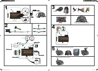
Page 16 - Carry out the installation in the following steps:
16 - English 3. INSTALLATION 3. Installation This chapter describes how to install the Husqvarna robotic lawnmower. Before starting the installation read the previous chapter 2. Presentation . Read also through this entire chapter before beginning the installation. How the installation is done also ...
Page 17 - Ideal position for the charging station
English - 17 3. INSTALLATION • Transformer (20) • Low voltage cable (17) • Staples (21) • Connector for connecting the loop wire to the charging station (18) • Screws for the charging station (19) • Measurement gauge (22) • Couplers for the loop wire (23) During installation you will also need: • Ha...
Page 19 - Installation of the boundary wire; Connecting the transformer; • Close to the charging station
English - 19 3. INSTALLATION If the installation is done in a working area with a steep slope (such as around a house on a hill), the charging station should be placed in the area at the bottom of the slope. This makes it easier for the robotic lawnmower to follow the guide wire to the charging stat...
Page 21 - Position the charging station in a suitable spot.; Charging the battery
English - 21 3. INSTALLATION Installation and connecting the charging station 1. Position the charging station in a suitable spot. 2. Connect the low voltage cable to the charging station. 3. Connect the transformer’s power cable to a 230 V wall socket. If the wall socket is outdoors, it is importan...
Page 22 - Plan where to lay the boundary wire; The boundary wire must be laid so that:
22 - English 3. INSTALLATION 3.4 Installation of the boundary wire The boundary wire can be installed in one of the following ways:1. Securing the wire to the ground with staples.It is preferable to staple down the boundary wire if you want to make adjustments to the boundary loop during the first f...
Page 23 - Working area boundaries; The robotic lawnmower must never run over
English - 23 3. INSTALLATION Working area boundaries If a high obstacle, for example a wall or fence, borders the working area, the boundary wire should be laid 30 cm from the obstacle. This will prevent the robotic lawnmower from colliding with the obstacle and reduce body wear. About 20 cm around ...
Page 24 - MAN; Passages when mowing
24 - English 3. INSTALLATION Boundaries within the working area Use the boundary wire to demarcate areas inside the working area by creating islands around obstacles which cannot withstand a collision, for example, flowerbeds, bushes and fountains. Lay the wire up to and around the area to be demarc...
Page 25 - Slopes; Outside
English - 25 3. INSTALLATION Slopes The boundary wire can be laid across a slope that slants less than 10%. The boundary wire should not be laid across a slope that is steeper than 10%. There is a risk that the robotic lawnmower will find it difficult to turn there. The robotic lawnmower will then s...
Page 26 - Laying the boundary wire; If you intend to staple down the boundary wire:; Loop for connecting the guide wire
26 - English 3. INSTALLATION Laying the boundary wire If you intend to staple down the boundary wire: • Cut the grass very low with a standard lawnmower or a trimmer where the wire is to be laid. It will then be easier to lay the wire close to the ground and the risk of the robotic lawnmower cutting...
Page 28 - Connecting the boundary wire; Connect the boundary wire to the charging station:
28 - English 3. INSTALLATION 3.5 Connecting the boundary wire Connect the boundary wire to the charging station: 1. Place the wire ends in the connector: • Open the connector. • Place the wire in the connector grip. 2. Press the connectors together using a pair of pliers. Press until you hear a clic...
Page 29 - At least 30 cm
English - 29 3. INSTALLATION 3.6 Installation of the guide wire The guide wire is a wire that is laid from the charging station towards, for instance, a remote part of the working area or through a narrow passage to be then connected with the boundary loop. The same cable roll is used for both the b...
Page 30 - Laying and connecting the guide wire
30 - English 3. INSTALLATION Laying and connecting the guide wire 1. Run the wire through the slot in the bottom of the charger plate. 2. Fit the connector to the guide wire in the same way as for the boundary wire described in 3.5 Connecting the boundary wire . Connect it to the contact pin on the ...
Page 31 - • - In the passage, the guide wire must therefore
English - 31 3. INSTALLATION • - In the passage, the guide wire must therefore be placed so that the robotic lawnmower has as much space to run in as possible. The distance between the boundary loop and the guide wire must however be at least 30 cm. If the guide wire has to be installed on a steep s...
Page 32 - Staple down/bury the connector in the lawn.; Checking the installation; See
32 - English 3. INSTALLATION 6. Connect the guide wire to the boundary wire using a coupler: Insert the boundary wire in each of the holes in the coupler. Insert the guide wire in the centre hole in the coupler. Check that the wires are fully inserted into the coupler so that the ends are visible th...
Page 33 - on page 4 to make a note of the
English - 33 3. INSTALLATION 3.8 First start-up and calibration Before the robotic lawnmower is operated, a start-up sequence in the robotic lawnmower's menu must be carried out as well as an automatic calibration of the guide signal. The calibration is also a good test to see that the installation ...
Page 35 - Charging a flat battery; Set the main switch to position
English - 35 4. USE 4. Use 4.1 Charging a flat battery When the robotic lawnmower is new or has been stored for a long period, the battery will be flat and needs to be charged before starting. Charging takes approximately 80 to 100 minutes. 1. Set the main switch to position 1 . 2. Park the robotic ...
Page 36 - Example; Example 1; Operation
36 - English 4. USE 4.2 Using the timer The lawn should not be cut too often to obtain the best mowing result. Use the timer function (see 6.3 Timer on page 44.) to avoid a downtrodden lawn. When setting the timer, calculate that the robotic lawnmower mows about 45 m 2 per hour and day (about 30 m 2...
Page 37 - Automower
English - 37 4. USE If the timer setting is divided into two work periods, the standby period can be divided into a number of periods. The total standby time must however be at least 6 hours (8 hours for Automower ® 305). Example 2 The times used in this example are applicable to the Automower ® 305...
Page 38 - Restart; Adjusting the cutting height
38 - English 4. USE 4.4 Stopping 1. Press the STOP button. The robotic lawnmower stops, the blade motor stops and the control panel cover opens. Restart 1. Push the Start button. 2. Shut the cover within 10 seconds. The robotic lawnmower starts automatically. 4.5 Switching off 1. Press the STOP butt...
Page 40 - Operation selection
40 - English 5. CONTROL PANEL 5.1 Operation selection The operation selection button is symbolised by a house. When the button has been pressed, the selected operation mode is shown in the display. By consecutively pressing the button many times, one can choose between three different operation mode...
Page 42 - Browse between menus; return arrow; to go up a step in the; Home; button pressed in for; Number series
42 - English 6. MENU FUNCTIONS 6. Menu functions 6.1 Main menu The main menu consists of four options: • Timer • Installation • Security • Settings There are a number of submenus under each option. You can access all the functions to set the robotic lawnmower settings via these. Browse between menus...
Page 44 - Work hours 1; OK; Work days
44 - English 6. MENU FUNCTIONS 6.3 Timer The lawn should not be cut too often to obtain the best mowing result. Consequently, it is important to limit the operating time using the timer function if the working area is less than the robotic lawnmower's working capacity. When the robotic lawnmower is ...
Page 45 - Guide width
English - 45 6. MENU FUNCTIONS 6.4 Installation The following operating settings are available via this selection in the main menu. • Guide width to select the distance from the guide wire the mower is allowed to travel when it follows this to and from the charging station. • Remote start 1 to contr...
Page 46 - With this function activated, (any option other than; Test IN; function to
46 - English 6. MENU FUNCTIONS Wide In a wide corridor, the robotic lawnmower mows at more varied distances from the guide wire. A garden that is open and free of narrow passages should have a wide corridor to minimise the risk of tracks forming. Medium In a medium wide corridor, the robotic lawnmow...
Page 47 - Remote start 2
English - 47 6. MENU FUNCTIONS The following five options can be selected; - Never (0%)- Rarely (approx. 20%)- Medium (approx. 50%)- Often (approx. 80%) - Always (100%) Select the percentage that corresponds to the size of the remote area relative to the total working area. If the remote area is for...
Page 48 - Test settings; Test OUT
48 - English 6. MENU FUNCTIONS Test settings In the Test settings menu, it is possible to test settings for Remote start 1 and that the selected guide width works for the garden in question. Test OUT The Test OUT function is used to test exit settings and to calculate the distance from the charging ...
Page 49 - Memo
English - 49 6. MENU FUNCTIONS Test IN The Test IN function allows you to test how well the robotic lawnmower docks with the charging station. Test IN can only be performed after Test OUT has been performed. Selecting this function causes the mower to travel directly along the guide wire towards the...
Page 50 - Security level; Enter PIN code; Low; Medium; High
50 - English 6. MENU FUNCTIONS Security level There are three security levels to choose from: low, medium and high Low and medium security prohibits access to the robotic lawnmower if the PIN code is unknown. High security also includes a warning that beeps if the correct PIN code is not entered aft...
Page 51 - New loop signal; Language
English - 51 6. MENU FUNCTIONS New loop signal The loop signal is randomly selected to create a unique link between the mower and the charging station. In rare cases, there may be a need to generate a new signal, for instance if two adjacent installations have a very similar signal. • Put the mower ...
Page 52 - Reset user settings; Select; . Enter the correct PIN code and press
52 - English 6. MENU FUNCTIONS Reset user settings This function allows you to reset the robotic lawnmower to the default settings the mower had when it left the factory. • Select Reset user settings in the menu and press OK . Enter the correct PIN code and press OK . Time & Date Language Reset ...
Page 53 - - Installation proposals and settings
English - 53 7. GARDEN EXAMPLES 7. Garden examples - Installation proposals and settings The mower's behaviour is controlled to a certain extent by what settings are made. Adapting the mower’s garden settings according to the shape of the garden makes it easier for the mower to frequently reach all ...
Page 54 - Installation proposals and settings
54 - English 7. GARDEN EXAMPLES Area Timer Proportion Guide width Remarks 500 m 2 . A number of islands and a 25% slope. 07:00-23:00 (factory setting)Monday-Sunday Rarely (factory setting) Medium Place the charging station in the lower part of the working area. Lay the guide wire at an angle over th...
Page 57 - Robotic lawnmower
English - 57 8 . MAINTENANCE 8. Maintenance Check and clean the Husqvarna robotic lawnmower regularly and replace worn parts if necessary to improved operating reliability and to ensure a longer service life. For more information on cleaning, see 8.4 Cleaning on page 58. When the robotic lawnmower i...
Page 58 - Charging station; Testing of the mower's function and components.; After winter storage
58 - English 8 . MAINTENANCE Charging station Store the charging station and transformer indoors. The boundary wire and the guide wire can be left in the ground. The ends of the wires should be protected from damp by putting them in a container with grease for instance. 8.2 Service Leave your roboti...
Page 59 - Chassis and blade disc; Set the main switch in position; Chassis
English - 59 8 . MAINTENANCE Chassis and blade disc 1. Set the main switch in position 0 . 2. Wear protective gloves. 3. Lift the robotic lawnmower onto its side. 4. Clean the blade disc and chassis using e.g. a dish brush. At the same time, check that the blade disc rotates freely in relation to th...
Page 61 - Replacing the battery
English - 61 8 . MAINTENANCE To replace the blades: 1. Set the main switch in position 0 . 2. Wear protective gloves. 3. Turn the robotic lawnmower upside down. 4. Rotate the skid plate so that its hole aligns with the screw for the blade. Only applicable for Automower ® 308. 5. Remove the screw. Us...
Page 63 - The blade disc lies in a pool of water.
English - 63 9. TROUBLESHOOTING 9. Troubleshooting In this chapter, a number of messages are listed which may be shown in the display if there is a malfunction. There is a proposal as to the cause and steps to take for each message. This chapter also presents some symptoms that can guide you if the ...
Page 64 - Message
64 - English 9. TROUBLESHOOTING Trapped The robotic lawnmower has got caught in something. Free the robotic lawnmower and rectify the reason for it becoming trapped. The robotic lawnmower is stuck behind a number of obstacles. Check if there are any obstacles which make it hard for the robotic lawnm...
Page 66 - Indicator lamp in the charging station; Light
66 - English 9. TROUBLESHOOTING 9.2 Indicator lamp in the charging station For a fully functional installation, the indicator lamp in the charging station must emit a solid green light. If something else appears, follow the troubleshooting guide below. There is more troubleshooting help on www.autom...
Page 68 - timer; START
68 - English 9. TROUBLESHOOTING The robotic lawnmower vibrates Damaged blades lead to imbalance in the cutting system. Inspect the blades and screws and replace them if necessary. See 8.7 Blades on page 60. Many blades in the same position lead to imbalance in the cutting system. Check that only one...
Page 69 - Finding breaks in the loop wire; Indicator lamp in the
English - 69 9. TROUBLESHOOTING 9.4 Finding breaks in the loop wire Breaks in the loop wire are usually the result of unconscious physical damage to the wire such as when gardening with a shovel. In countries with ground frost, even sharp stones that move in the ground can damage the wire. Breaks ca...
Page 75 - EU DECLARATION OF CONFORMITY; EU Declaration of Conformity; EU Declaration of conformity (Only applies to Europe)
English - 75 13. EU DECLARATION OF CONFORMITY 13. EU Declaration of Conformity EU Declaration of conformity (Only applies to Europe) Husqvarna AB , SE-561 82 Huskvarna, Sweden, hereby declares under sole responsibility that the robotic lawnmowers Husqvarna Automower ® 305 and Automower ® 308 with se...
Page 78 - ORIGINAL INSTRUCTIONS
www.automower.com 115 59 08-26 ORIGINAL INSTRUCTIONS AUTOMOWER is a trademark owned by Husqvarna AB. Copyright © 2013 HUSQVARNA. All rights reserved.


 Husqvarna 115iHD55
User Manual
Husqvarna 115iHD55
User Manual
 Husqvarna 115iL
User Manual
Husqvarna 115iL
User Manual
 Husqvarna 115iPT4
User Manual
Husqvarna 115iPT4
User Manual
 Husqvarna 120
User Manual
Husqvarna 120
User Manual
 Husqvarna 120iTK4-P
User Manual
Husqvarna 120iTK4-P
User Manual
 Husqvarna 120 Mark II
User Manual
Husqvarna 120 Mark II
User Manual
 Husqvarna 122C
User Manual
Husqvarna 122C
User Manual
 Husqvarna 122HD45
User Manual
Husqvarna 122HD45
User Manual
 Husqvarna 122L
Quick Guide
Husqvarna 122L
Quick Guide
 Husqvarna 122LK
User Manual
Husqvarna 122LK
User Manual
 Husqvarna 122LKE
Quick Guide
Husqvarna 122LKE
Quick Guide
 Husqvarna 122LKH
Quick Guide
Husqvarna 122LKH
Quick Guide
 Husqvarna 122LKP
Quick Guide
Husqvarna 122LKP
Quick Guide
 Husqvarna 122RJ
Quick Guide
Husqvarna 122RJ
Quick Guide
 Husqvarna 125B
User Manual
Husqvarna 125B
User Manual