Grizzly Industrial G8749 - Manuals

Grizzly Industrial G8749 Grinding Machine – User Manual, Manual in PDF format online.
Manuals:
User Manual Grizzly Industrial G8749


Summary
iNtRODUctiON ............................................................................................................................... 2 Manual accuracy ........................................................................................................................ 2Contact info .........
-2- g8749 drum/Flap sander iNtRODUctiON We stand behind our machines. if you have any service questions, parts requests or general ques-tions about the machine, please call or write us at the location listed below. grizzly industrial, inc. 1203 lycoming Mall Circle Muncy, pa 17756 phone: (570) 546-9...
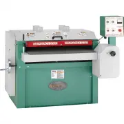
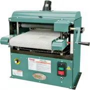
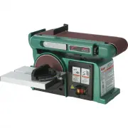
g8749 drum/Flap sander -3- identification Figure 3. Model g8749 identification. Mounting holes Motor sanding drum on/oFF switch Flap sander
Manual Grizzly Industrial G8749


Summary
INTRODUCTION ............................................................................................................................... 2 Manual Accuracy ........................................................................................................................ 2Contact Info .........
-2- G8749 Drum/Flap Sander INTRODUCTION We stand behind our machines. If you have any service questions, parts requests or general ques-tions about the machine, please call or write us at the location listed below. Grizzly Industrial, Inc. 1203 Lycoming Mall Circle Muncy, PA 17756 Phone: (570) 546-9...
G8749 Drum/Flap Sander -3- Identification Figure 3. Model G8749 identification. Mounting Holes Motor Sanding Drum ON/OFF Switch Flap Sander
Grizzly Industrial Grinding Machines Manuals
-
 Grizzly Industrial G0450
User Manual
Grizzly Industrial G0450
User Manual
-
Grizzly Industrial G0450
Manual
-
 Grizzly Industrial G0459
User Manual
Grizzly Industrial G0459
User Manual
-
Grizzly Industrial G0459
Manual
-
 Grizzly Industrial G0489
User Manual
Grizzly Industrial G0489
User Manual
-
Grizzly Industrial G0489
Manual
-
 Grizzly Industrial G0529
User Manual
Grizzly Industrial G0529
User Manual
-
Grizzly Industrial G0529
Manual
-
 Grizzly Industrial G0538
User Manual
Grizzly Industrial G0538
User Manual
-
Grizzly Industrial G0538
Manual
-
 Grizzly Industrial G0582
User Manual
Grizzly Industrial G0582
User Manual
-
Grizzly Industrial G0582
Manual
-
 Grizzly Industrial G0716
User Manual
Grizzly Industrial G0716
User Manual
-
 Grizzly Industrial G0723
User Manual
Grizzly Industrial G0723
User Manual
-
Grizzly Industrial G0723
Manual
-
 Grizzly Industrial G0739
User Manual
Grizzly Industrial G0739
User Manual
-
 Grizzly Industrial G0787
User Manual
Grizzly Industrial G0787
User Manual
-
 Grizzly Industrial G0839P
User Manual
Grizzly Industrial G0839P
User Manual
-
 Grizzly Industrial G0864
User Manual
Grizzly Industrial G0864
User Manual
-
 Grizzly Industrial G0897
User Manual
Grizzly Industrial G0897
User Manual