Page 3 - Table of Contents
Table of Contents INTRODUCTION ............................................... 2 Manual Accuracy ........................................... 2Contact Info.................................................... 2Machine Description ...................................... 2Identification ....................
Page 4 - INTRODUCTION; Machine Description; Contact Info; Manual Accuracy
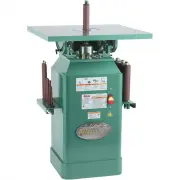
-2- Model G1071 (Mfd. Since 11/10) INTRODUCTION An oscillating spindle sander is used to sand the edges of contoured or irregularly shaped workpieces. The cast-iron sanding table provides a solid plat-form for supporting workpieces and can tilt for sanding beveled edges. The integrated dust collecti...
Page 5 - Identification
Model G1071 (Mfd. Since 11/10) -3- Identification Figure 1. Identification. Cast Iron Work Table Table Insert Table Tilt Scale ON/OFF Switch Cabinet Stand Table Tilt Lock Spindle Rack Additional Sizes of Spindles For Your Own Safety Read Instruction Manual Before Operating Spindle Sander a) Wear eye...
Page 6 - MODEL G1071 1 HP OSCILLATING SPINDLE SANDER; Machine Data Sheet
-4- Model G1071 (Mfd. Since 11/10) The information contained herein is deemed accurate as of 5/23/2019 and represents our most recent product specifications. Due to our ongoing improvement efforts, this information may not accurately describe items previously purchased. PAGE 1 OF 2 Model G1071 MACHI...
Page 8 - NOTICE; Safety Instructions for Machinery
-6- Model G1071 (Mfd. Since 11/10) ELECTRICAL EQUIPMENT INJURY RISKS. You can be shocked, burned, or killed by touching live electrical components or improperly grounded machinery. To reduce this risk, only allow qualified service personnel to do electrical installation or repair work, and always di...
Page 10 - Additional Safety for Spindle Sanders
-8- Model G1071 (Mfd. Since 11/10) Serious injury or death can occur from fingers, clothing, jewelry or hair getting entangled in rotating spindle or other moving components. Abrasion injuries can occur from touching rotating sanding drum with bare skin. Workpieces thrown by drum can strike operator...
Page 11 - SECTION 2: POWER SUPPLY; Availability
Model G1071 (Mfd. Since 11/10) -9- SECTION 2: POWER SUPPLY Availability Before installing the machine, consider the avail-ability and proximity of the required power supply circuit. If an existing circuit does not meet the requirements for this machine, a new circuit must be installed. To minimize t...
Page 13 - Voltage Conversion
Model G1071 (Mfd. Since 11/10) -11- 4. Use wire nuts to connect wires as indicated in Figure 5. Twist wire nuts onto their respec- tive wires and wrap them with electrical tape so they will not come loose. 5. Close and secure motor junction box. 6. Install a 6-15 plug according to manufac- turer's i...
Page 14 - Needed for Setup; Unpacking
-12- Model G1071 (Mfd. Since 11/10) SECTION 3: SETUP The following are needed to complete the setup process, but are not included with your machine. Description Qty• Safety Glasses ........................................... 1 • Dust Collection System .............................. 1 • 4" Dust H...
Page 15 - Inventory
Model G1071 (Mfd. Since 11/10) -13- Inventory Box 1 (Figure 6) Qty A. Table Assembly (Table, Trunnion, Dust Chute) .................... 1 B. Sanding Spindles 1 ⁄ 4 " x 5" ........................................................ 1 3 ⁄ 8 " x 6" ............................................
Page 16 - Cleanup; Site Considerations; Workbench Load; Placement Location
-14- Model G1071 (Mfd. Since 11/10) Cleanup The unpainted surfaces of your machine are coated with a heavy-duty rust preventative that prevents corrosion during shipment and storage. This rust preventative works extremely well, but it will take a little time to clean. Be patient and do a thorough jo...
Page 17 - Assembly
Model G1071 (Mfd. Since 11/10) -15- 4. Secure the dust chute to the trunnion assem- bly with (2) 3 ⁄ 8 "-16 x 1 1 ⁄ 2 " hex bolts, 3 ⁄ 8 " lock washers and 3 ⁄ 8 "-16 hex nuts (see Figure 9). Figure 10. Table stop bolt. 5. Thread the table stop bolt and jam nut into the sander base, ...
Page 19 - Check Gearbox Oil
Model G1071 (Mfd. Since 11/10) -17- 13. Thread four of the 1 ⁄ 4 "-20 x 5 ⁄ 8 " set screws into the threaded holes on each table insert, as shown in Figure 15. Note: The roll pins and set screws must not protrude above the top surface of the table insert or they will interfere with sanding o...
Page 20 - Test Run
-18- Model G1071 (Mfd. Since 11/10) Test Run Once assembly is complete, test run the machine to ensure it is properly connected to power and safety components are functioning correctly. If you find an unusual problem during the test run, immediately stop the machine, disconnect it from power, and fi...
Page 21 - SECTION 4: OPERATIONS; Operation Overview
Model G1071 (Mfd. Since 11/10) -19- SECTION 4: OPERATIONS Operation Overview The purpose of this overview is to provide the nov-ice machine operator with a basic understanding of how the machine is used during operation, so the machine controls/components discussed later in this manual are easier to...
Page 22 - Sanding Tips
-20- Model G1071 (Mfd. Since 11/10) • Replace the sanding sleeve with a higher grit to achieve a finer finish. Avoid skipping grits, as this will leave scratches in the wood. • Extend the life of the sanding sleeve by regularly using a PRO-STIK ® sanding pad ( Accessories on Page 25). • When bevel s...
Page 23 - Sanding Spindles
Model G1071 (Mfd. Since 11/10) -21- 4. Insert the threaded end of the spindle shaft into the spindle mounting hole, and screw it down by hand as shown in Figure 20. NOTICE DO NOT tighten the sanding spindle with a wrench! The sanding action will further tighten the spindle to the sander. Using a wre...
Page 24 - Sanding Sleeves
-22- Model G1071 (Mfd. Since 11/10) Sanding Sleeves The Model G1071 is supplied with 10 sanding sleeves. Use coarse grits for fast material removal and a rough finish. Use fine grits for slower mate-rial removal and a smoother finish. When chang-ing from a coarse sleeve to a finer sleeve on a partic...
Page 25 - Table Inserts
Model G1071 (Mfd. Since 11/10) -23- Table Inserts The Model G1071 is supplied with three different sized table inserts. The inserts are designed to reduce the gap between the spindle and the table opening. The hole in each insert is oblong to allow clearance when the table is tilted. NOTICE A lways ...
Page 26 - Bevel Sanding
-24- Model G1071 (Mfd. Since 11/10) Bevel Sanding The Model G1071 has a tilting table to allow bevel sanding at a variety of angles. NOTICE Bevel sanding on a spindle sander is NOT an exact science. When the table is tilted to 45˚, the actual angle sanded on the edge of a workpiece will change if th...
Page 27 - SECTION 5: ACCESSORIES; Basic Eye Protection; order online at
Model G1071 (Mfd. Since 11/10) -25- ACCESSORIES SECTION 5: ACCESSORIES PRO-STIK ® Abrasive Surface Cleaners Extend the life of your sanding discs and sleeves! Choose the Pro-Stik ® with a handle for greater control or without a handle for more usable area. Size Model 1 1 ⁄ 2 " x 1 1 ⁄ 2 " x ...
Page 29 - SECTION 6: MAINTENANCE; Schedule; Protecting
Model G1071 (Mfd. Since 11/10) -27- SECTION 6: MAINTENANCE Always disconnect power to the machine before performing maintenance. Failure to do this may result in serious person- al injury. For optimum performance from this machine, this maintenance schedule must be strictly followed. OngoingTo minim...
Page 30 - Gearbox Oil
-28- Model G1071 (Mfd. Since 11/10) Gearbox Oil The spindle gearbox contains 4.5 Qts. of 90 Wt. gear oil. Replace the gear oil after the first two hours of use, and then after approximately every 1000 hours of use. Remove the fill cap first, then drain the gear oil from the drain plug located inside...
Page 31 - Troubleshooting
Model G1071 (Mfd. Since 11/10) -29- Troubleshooting Motor & Electrical Symptom Possible Cause Possible Solution Machine does not start or a breaker trips. 1. Switch disabling key removed.2. Power supply switched OFF or at fault.3. Plug/receptacle at fault/wired wrong.4. Start capacitor at fault....
Page 32 - Sanding Operations
-30- Model G1071 (Mfd. Since 11/10) Symptom Possible Cause Possible Solution Deep s an din g grooves or scars in workpiece. 1. Sanding sleeve too coarse for the desired finish. 2. Workpiece sanded across the grain. 3. Too much sanding force on workpiece. 1. Use a finer grit sanding sleeve. 2. Sand w...
Page 33 - Wiring Safety Instructions
Model G1071 (Mfd. Since 11/10) -31- SHOCK HAZARD. Working on wiring that is con-nected to a power source is extremely dangerous. Touching electrified parts will result in personal injury including but not limited to severe burns, electrocution, or death. Disconnect the power from the machine before ...
Page 34 - Wiring Diagram
-32- Model G1071 (Mfd. Since 11/10) READ ELECTRICAL SAFETY ON PAGE 31! Wiring Diagram Ground View this page in color at www.grizzly.com. Neutral Hot Hot Hot Ground Ground 120 VAC (Prewired) 5-15 Plug 240 VAC (As Recommended) 6-15 Plug PADDLE SWITCH (viewed from behind) Ground The motor wiring shown ...
Page 36 - Main Parts List
-34- Model G1071 (Mfd. Since 11/10) BUY PARTS ONLINE AT GRIZZLY.COM ! Scan QR code to visit our Parts Store. REF PART # DESCRIPTION REF PART # DESCRIPTION 1 P1071001 TABLE 73V2 P1071073V2 MOTOR CORD 16G 3W 30" V2.11.10 2 P1071002 INSERT 1-3/4 X 2-3/16 74V2 P1071074V2 POWER CORD 16G 3W 12' 5-15P ...
Page 37 - Base
Model G1071 (Mfd. Since 11/10) -35- BUY PARTS ONLINE AT GRIZZLY.COM ! Scan QR code to visit our Parts Store. 89 115 116 109 63 59 111 53 109 106 105 105 106 111 111 57 51 110 110 50 57 111 58 52 110 110 34 49 48 89 32 30 28 27 26 110 110 29 110 31 33 110 110 34 34 34 34 77V2 78 79 77-1 110 34 110 36...