Grizzly Industrial G0739 - Manuals

User Manual Grizzly Industrial G0739


Summary
Table of Contents INTRODUCTION ............................................... 2 Contact Info.................................................... 2Manual Accuracy ........................................... 2Identification ................................................... 3 SECTION 1: SAFETY ........
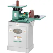
-2- Model G0739 (Mfd. Since 6/15) INTRODUCTION We are proud to provide a high-quality owner’s manual with your new machine! We made every effort to be exact with the instruc-tions, specifications, drawings, and photographs in this manual. Sometimes we make mistakes, but our policy of continuous impr...
Model G0739 (Mfd. Since 6/15) -3- Figure 1. Machine identification. Identification Spindle Hex Nut Spindle Drum and Sanding Sleeve ON/OFF Paddle Switch w/Disabling Key Table Insert Table Spindle Washers (Not Shown) Table Inserts Sander Body Power Cord Dust Port Drums and Sanding Sleeves Spindle Wash...
Grizzly Industrial Grinding Machines Manuals
-
 Grizzly Industrial G0450
User Manual
Grizzly Industrial G0450
User Manual
-
Grizzly Industrial G0450
Manual
-
 Grizzly Industrial G0459
User Manual
Grizzly Industrial G0459
User Manual
-
Grizzly Industrial G0459
Manual
-
 Grizzly Industrial G0489
User Manual
Grizzly Industrial G0489
User Manual
-
Grizzly Industrial G0489
Manual
-
 Grizzly Industrial G0529
User Manual
Grizzly Industrial G0529
User Manual
-
Grizzly Industrial G0529
Manual
-
 Grizzly Industrial G0538
User Manual
Grizzly Industrial G0538
User Manual
-
Grizzly Industrial G0538
Manual
-
 Grizzly Industrial G0582
User Manual
Grizzly Industrial G0582
User Manual
-
Grizzly Industrial G0582
Manual
-
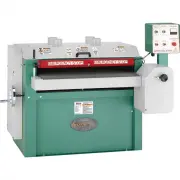
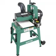 Grizzly Industrial G0716
User Manual
Grizzly Industrial G0716
User Manual
-
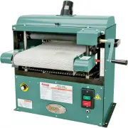
 Grizzly Industrial G0723
User Manual
Grizzly Industrial G0723
User Manual
-
Grizzly Industrial G0723
Manual
-
 Grizzly Industrial G0787
User Manual
Grizzly Industrial G0787
User Manual
-
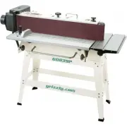 Grizzly Industrial G0839P
User Manual
Grizzly Industrial G0839P
User Manual
-
 Grizzly Industrial G0864
User Manual
Grizzly Industrial G0864
User Manual
-
 Grizzly Industrial G0897
User Manual
Grizzly Industrial G0897
User Manual
-
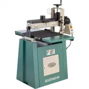 Grizzly Industrial G0920
User Manual
Grizzly Industrial G0920
User Manual