Page 2 - PRODUCT LABEL; Approval Requirements for Domestic Gas cooking appliances
2 Dear Customer, Thank you for having purchased and given your preference to our product. The safety precautions and recommendations reported below are for your own safety and that of others. They will also provide a means by which to make full use of the features offered by your appliance. Please k...
Page 3 - professionally qualified technician.; This film must be removed before using the; ■ IMPORTANT: The use of suitable protective clothing/gloves is
3 IMPORTANT SAFETY PRECAUTIONS AND RECOMMENDATIONS IMPORTANT: This appliance is designed and manufactured solely for the cooking of domestic (household) food and is not suitable for any non domestic application and therefore should not be used in a commercial environment. The appliance guarantee wil...
Page 4 - ■ WARNING: During use the appliance and its accessible parts
4 ■ Do not use a steam cleaner because the moisture can get into the appliance thus make it unsafe. ■ Do not touch the appliance with wet or damp hands (or feet). ■ Do not use the appliance whilst in barefoot. ■ If you should decide not to use this appliance any longer (or decide to substitute anoth...
Page 7 - Hob rail; WARNING – VERY IMPORTANT !; Do not place towels/cloths etc onto the hob rail or oven door; TO AVOID DAMAGE TO THE APPLIANCE:; Do not lift/move the cooker by the hob rail or oven door handle/s.
7 This figure is indicative only Hob rail Door handle/s WARNING – VERY IMPORTANT ! FIRE/OVERHEATING HAZARD: ■ Do not place towels/cloths etc onto the hob rail or oven door handle/s whilst the product is in use or hot. TO AVOID DAMAGE TO THE APPLIANCE: ■ Do not lift/move the cooker by the hob rail or...
Page 8 - INSTALLATION; ELECTRICAL REQUIREMENTS; the load specified on the plate.
8 INSTALLATION CAUTION: ■ This appliance must be installed according to AS/NZS 5601.1 (latest edition). ■ This appliance must be installed in accordance with these installation instructions. ■ This appliance shall only be serviced by authorized personnel. ■ This appliance is to be installed only by ...
Page 9 - CLEARANCES; Overhead Clearances; clearance be less than 450 mm.; Rear and Side Clearances; surface of the hob, or the horizontal surface requirement above.; Protection of combustible surfaces; Do not install the cooker near flammable materials (eg curtains).; Figure 1
9 CLEARANCES Installation clearances and protection of combustible surfaces shall comply with the current local regulations eg. AS/NZS5601.1 (latest edition) Gas Installations code. Installation shall comply with the dimension in fig. 1a bearing in mind that. Overhead Clearances In no case shall the...
Page 10 - Area for GAS; GAS AND ELECTRIC CONNECTION; Figure 2; FITTING THE ADJUSTABLE FEET; the fitting of the feet.; LEVELLING THE COOKER; Figure 4
10 max 290 mm Dotted line showing the position of the cooker when installed Area for GAS and ELECTRIC connection GAS AND ELECTRIC CONNECTION Figure 2 FITTING THE ADJUSTABLE FEET The adjustable feet must be fitted to the base of the cooker before use (figs. 3, 4). Rest the rear of the cooker on a pie...
Page 11 - MOVING THE COOKER; Figure 7a; FIXING THE BACKGUARD; fig. 6 and fix it by screwing the central; Figure 6
11 MOVING THE COOKER WARNING: When raising cooker to upright position always ensure two people carry out this manoeuvre to prevent damage to the adjustable feet (fig. 7a). WARNING - Be carefull: Do not lift the cooker by the door handle when raising to the upright position (fig. 7b). WARNING: When m...
Page 12 - of the anti-tilt bracket have to be fitted.; Before drilling the holes, check that; Access the bracket and fit the lock pin:; Figure 8
12 ANTI-TILT BRACKET Important! To restrain the appliance and prevent it tipping accidentally, fit a bracket to its rear to fix it securely to the wall. Make sure you also fit the supplied lock pin to the anti-tilt bracket. To fit the anti-tilt bracket: 1. After you have located where the cooker is ...
Page 13 - BOTTOM METAL PLINTH; in the instruction sheet supplied with the kit itself.
13 900mm BOTTOM METAL PLINTH A metal plinth can be fitted at the bottom of the appliance to cover the feet. This plinth is supplied with the appliance in a separate kit and it shall be fitted as indicated in the instruction sheet supplied with the kit itself. IMPORTANT: This bottom metal plinth is s...
Page 14 - and is secured as per appropriate gas installation codes.; is not kinked, subjected to abrasion or permanently deformed.; LEAK-TESTING AND FLAME-TESTING THE COOKER; tighten or replace connections as appropriate.
14 GAS SUPPLY ■ The connection must be performed by an authorised person according to the relevant standards. ■ Before connecting the appliance to the gas main, mount the brass conical adaptor onto the gas inlet pipe, upon which the gasket has been placed (figs. 12a - 12b). Conical adaptor and gaske...
Page 15 - Plug
15 Gas connection for ULPG Gas inlet pipe Nipple Gasket Brass conical adaptor (Thread tight: use suitable seal) Test point adaptor Test point Gas connection for NATURAL GAS Gas inlet pipe Nipple Gasket Brass conical adaptor (Thread tight: use suitable seal) Gas regulator Test point Figure 12a Figure...
Page 16 - IMPORTANT
16 2. Adjust the test point pressure or supply pressure to the value which is appropriate for the gas type. 3. The operation of the appliance must be tested when installation is completed. ■ Turn on the appliance gas controls and light each burner individually and in combination. Check for a well de...
Page 17 - Inside crown of DUAL burner:
17 J Auxiliary, Semi-rapid and Rapid burners J Injectors for outer crown J Injector for inner crown Dual burner to the minimum position. If the burner does not remain lit, increase the minimum gas rate setting.The procedure for adjusting the minimum gas rate setting is described below. Auxiliary, se...
Page 18 - TABLE FOR THE CHOICE OF THE INJECTORS; Natural gas; LUBRICATION OF THE GAS VALVES
18 TABLE FOR THE CHOICE OF THE INJECTORS Natural gas ULPG Test Point Pressure [kPa] 1.0 2.75 BURNER Injector Orifice Dia. [mm] Gas Consumption [MJ/h] Injector Orifice Dia. [mm] Gas Consumption [MJ/h] Auxiliary (A) 0.92 3.90 0.56 3.90 Semi-rapid (SR) 1.17 6.50 0.70 6.30 Rapid (R) 1.54 11.75 0.98 11.7...
Page 19 - USE AND CARE; Do NOT modify this appliance.; USING THE OVEN FOR THE FIRST TIME
19 USE AND CARE CAUTION: ■ This appliance must be used only for the task it has explicitly been designed for, that is for domestic cooking of foodstuffs. Any other form of usage is to be considered as inappropriate and therefore dangerous. ■ Do NOT place combustible materials or products on this app...
Page 20 - GREASE FILTER (OPTIONAL COMPONENT, CAN BE PURCHASED; Slide in the grease filter on the back of the oven as in fig. 19.; Clean the filter after any cooking!; When baking pastry etc. this filter should be removed.; TELESCOPIC SLIDING SHELF SUPPORTS; The slides to the top wire of a rack. They do not fit on the lower wire.
20 Figure 19 GREASE FILTER (OPTIONAL COMPONENT, CAN BE PURCHASED SEPARATELY) ■ A special screen can be fitted at the back of the oven to catch grease particles, mainly when meat is being roasted. Slide in the grease filter on the back of the oven as in fig. 19. ■ Clean the filter after any cooking! ...
Page 21 - To remove the telescopic sliding shelf supports:
21 Left Right Figure 20 To remove the telescopic sliding shelf supports: ■ Remove the side racks and the catalytic liners. ■ Lay down the telescopic sliding shelf support and side racks, with the telescopic sliding shelf support underneath. ■ Find the safety locks. These are the tabs that clip over ...
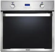
Page 22 - Oven temperature indicator light; CONTROL PANEL; cooking temperature and duration.
22 Controls description 1. Front right burner control knob2. Rear right burner control knob3. Central burner control knob4. Rear left burner control knob5. Front left burner control knob6. Oven temperature control knob7. Oven function selector control knob8. Electronic programmer Pilot lamp 9. Oven ...
Page 23 - GAS HOB; The electric ignition is incorporated in the knobs.; GAS BURNERS
23 Figure 23 GAS HOB Notes: ■ The electric ignition is incorporated in the knobs. ■ The appliance has a safety valve system fitted, the flow of gas will be stopped if and when the flame should accidentally go out. CAUTION: ■ If the burner is accidentally extinguished, turn the gas off at the control...
Page 24 - control panel achieves the following functions:; Knob
24 GAS BURNERS (Auxiliary, Semi-rapid and Rapid) Gas flow to the burners is adjusted by turning the knobs (illustrated in fig. 24) which control the valves.Turning the knob so that the symbols printed on itself point to the symbol printed on the control panel achieves the following functions: Knob p...
Page 25 - If the burner flames should go out for
25 LIGHTING GAS BURNERS FITTED WITH FLAME FAILURE SAFETY DEVICE AND ELECTRONIC IGNITION (Auxiliary, Semi-rapid and Rapid burners) 1. Check that the electricity is switched on to allow spark ignition. 2. The gas flow to the burner is controlled by taps with safety cut-out device. If the burner flame ...
Page 27 - minute and then repeat the lighting procedure.
27 LIGHTING GAS BURNERS FITTED WITH FLAME FAILURE SAFETY DEVICE AND ELECTRONIC IGNITION (Dual burner) 1. Check that the electricity is switched on to allow spark ignition. 2. The gas flow to the burner is controlled by a tap with safety cut-out device. If the burner flame should go out, the safety c...
Page 28 - When deep fat frying fill the pan only one third full of oil.; Place a damp cloth or correct fitting lid over; DO NOT; use water on the fire.; GRATE FOR SMALL PANS; do not use pans with concave or convex bases
28 CHOICE OF BURNER The burner must be chosen according to the diameter of the pans and energy required. For optimum efficiency uso a wok or pan no smaller than 230 mm diameter. Burners Pan diameter Auxiliary (*) 12 - 14 cm Semi-rapid 16 - 24 cm Rapid 24 - 26 cm Dual (with ONLY inner crown operating...
Page 29 - CORRECT USE OF THE DUAL BURNER; MUST BE PLACED ONLY; over the pan-rest for; WRONG
29 CORRECT USE OF THE DUAL BURNER (fig. 31 - 32) ■ The flat-bottomed pans are to be placed directly onto the pan-support. ■ To use the WOK, you must place the wok stand in the CORRECT position as shown in figs. 31 - 32. IMPORTANT: The special grille for wok pans (fig. 32) MUST BE PLACED ONLY over th...
Page 30 - GENERAL FEATURES; Upon first use, it is advisable to operate; OPERATING PRINCIPLES; oven muffle, which sends it through; COOKING WITH MULTIFUNCTION OVEN
30 Attention: The oven door becomes very hot during operation. Keep children away. WARNING: The door is hot, use the handle.During use the appliance becomes hot. Care should be taken to avoid touching heating elements inside the oven. GENERAL FEATURES As its name indicates, this is an oven that pres...
Page 32 - VENTILATED GRILL COOKING; Use with the oven door closed; CONVECTION COOKING WITH VENTILATION
32 UPPER HEATING ELEMENT In this position only the upper element is switched on. Heat is distributed by natural convection. The temperature must be regulated between 50°C and the maximum position with the thermostat knob. Recommended for: To complete cooking of dishes that require higher temperature...
Page 33 - COOKING ADVICE; The external parts of the appliance; Different foods such as fish, cake and meat
33 COOKING ADVICE The external parts of the appliance become hot during operation. Keep children well out of reach. STERILIZATION Sterilization of foods to be conserved, in full and hermetically sealed jars, is done in the following way: a. Set the switch to position .b. Set the thermostat knob to p...
Page 34 - USE OF THE GRILL; GRILLING AND “AU GRATIN”; hot during operation. Keep children well; OVEN COOKING; DISH; Cheese soufflé
34 possible, with a maximum difference of 20°C - 25°C. • The introduction of the different dishes in the oven must be done at different times in relation to the cooking times of each one. The time and energy saved with this type of cooking is obvious. USE OF THE GRILL Preheat the oven for about 5 mi...
Page 35 - ROTISSERIE; an electric motor fitted to the rear of the oven; USE OF THE ROTISSERIE; Attention: The oven door becomes very hot during operation.
35 ROTISSERIE This is used for spit roasting under the grill and comprises:• an electric motor fitted to the rear of the oven; • a stainless steel skewer provided with slide-out heatless handgrip and two sets of adjustable forks; • a skewer support to be fitted in the middle runner. The rotisserie m...
Page 36 - RECOMMENDED COOKING TEMPERATURE; Victoria sandwich
36 RECOMMENDED COOKING TEMPERATURE Food °C °F Gas Mark Shelf Position* Cooking Time (approx) CAKES Victoria sandwich 190 375 5 2 or 3 20-25 mins Small cakes/buns 190 375 5 1 and 2 15-20 mins Maidera cake 180 350 4 2 or 3 20 mins Fruit cake 170 325 3 3 1 3/4 hours Rich fruit cake 150 300 2 3 or 4 2 1...
Page 37 - DIGITAL ELECTRONIC PROGRAMMER; Description of the buttons:; AUTO
37 The electronic programmer is a device which groups together the following functions: ■ 24 hours clock with illuminated display. ■ Timer (up to 23 hours and 59 minutes). ■ Program for automatic oven cooking. ■ Program for semi-automatic oven cooking. DIGITAL ELECTRONIC PROGRAMMER Figure 36 Figure ...
Page 38 - symbol is flashing push the
38 Figure 38 Figure 39 ELECTRONIC CLOCK (fig. 38) The programmer is equipped with an electronic clock with illuminated numbers which indicates hours and minutes. Upon immediate connection of the oven or after a power cut, three zeros will flash on the programmer display. To set the correct time of d...
Page 39 - AUTOMATIC OVEN COOKING; flashes on the display and a; The cooking program may be cancelled; will flash and a buzzer
39 Figure 40 Figure 41 AUTOMATIC OVEN COOKING To cook food automatically in the oven, it is necessary to: 1. Set the length of the cooking period. 2. Set the end of the cooking time. 3. Set the temperature and the oven cooking program. These operations are done in the following way: 1. Set the lengt...
Page 40 - SEMI-AUTOMATIC COOKING; There are two ways to set your oven:
40 Figure 42 Figure 43 SEMI-AUTOMATIC COOKING This is used to automatically switch off the oven after the desired cooking time has elapsed. There are two ways to set your oven: 1. Set the length of the cooking time by pushing the button and the button to advance, or to go backwards if you have passe...
Page 41 - Maintenance Period Description; GENERAL ADVICE; and disconnected from the electrical power supply.; ENAMELLED PARTS; Dry preferably with a microfibre or soft cloth.; PRINTED SURFACES; irreparably damage the surface.; CLEANING AND MAINTENANCE
41 Maintenance Period Description Daily ■ Clean gas cooktop as per instructions below Monthly ■ Remove burner caps, burner rings & base and clean using non abrasive detergent & rinse in cold water & dry thoroughly before replacing back on hob ■ Clean ignitor tip & thermocouple using ...
Page 42 - CORRECTLY POSITIONED; It is essential to check that the burner flame distributor “
42 INSIDE OF OVEN The oven should always be cleaned after use when it has cooled down. The cavity should be cleaned using a mild detergent solution and warm water. Suitable proprietary chemical cleaners may be used after first consulting with the manufacturers recommendations and testing a small sam...
Page 44 - REPLACING THE OVEN LIGHT; following specifications; from your fingers can cause; Refit the protective cover “; OVEN FLOOR; The oven floor “; STORAGE COMPARTMENT; flammable material in the storage
44 REPLACING THE OVEN LIGHT WARNING: Ensure the appliance is switched off before replacing the lamp to avoid the possibility of electric shock. ■ Let the oven cavity and the heating elements to cool down. ■ Disconnect the appliance from the electrical power supply. ■ Remove the protective cover “ A ...
Page 45 - REMOVING THE OVEN DOOR
45 REMOVING THE OVEN DOOR The oven door can easily be removed as follows: ■ Open the door to the full extent (fig. 49a). ■ Open the lever “ A ” completely on the left and right hinges (fig. 49b). ■ Hold the door as shown in fig. 49d. ■ Gently close the door (until left and right hinge levers “ A ” a...
Page 46 - REFIT THE DOOR; place as shown in the figure 50b.; REMOVING AND REPLACING THE INNER DOOR GLASS PANE FOR CLEANING
46 REFIT THE DOOR 1. Hold the door firmly (fig. 50a). 2. Insert the hinge tongues into the slots, making sure that the groove drops into place as shown in the figure 50b. 3. Open the door to its full extent.4. Fully close the levers “ A ” on the left and right hinges, as shown in the figure 50c. 5. ...
Page 47 - CLEANING THE PANES OF GLASS; The oven door is fitted with no. 2 panes:; REMOVING THE INNER PANE OF; Open the door to the full extent (fig.
47 CLEANING THE PANES OF GLASS The oven door is fitted with no. 2 panes: ■ no. 1 outside; ■ no. 1 inner. To clean the panes on both sides it is ne- cessary to remove the inner pane as fol- lows. REMOVING THE INNER PANE OF GLASS 1. Lock the door open: ■ Open the door to the full extent (fig. 49a). ■ ...
Page 48 - fit into the door and to ensure that the
48 AFTER CLEANING, REPLACE THE INNER GLASS PANE When replacing the inner glass pane, make sure that: ■ You replace the pane correctly, as shown. The pane must be in the position described below in order to fit into the door and to ensure that the oven operates safely and correctly. To reassemble the...
Page 49 - SERVICE AND MAINTENANCE; Burner is reassembled and located correctly.; SERVICING THE APPLIANCE; Authorised Delonghi Service Agent:; Servicing shall be carried out only by authorized personnel.
49 SERVICE AND MAINTENANCE If the ignition spark fails to ignite or does not light the gas, check the following items before calling our Customer Service Centre to obtain the nearest Authorised Service Agent: ■ Burner is reassembled and located correctly. ■ Spark electrode and white ceramic are clea...
Page 50 - ELECTRIC DIAGRAM
50 ELECTRIC DIAGRAM Figure 52 TM C G S V CIR S1 LF N/7 1 1a L/8 PR TL M PA A T CF GIR 1 3 2 6 7 8 9 10 12 a b c f g h i k F1 TL1 TB N L
Page 51 - ELECTRIC DIAGRAM KEY
51 ELECTRIC DIAGRAM KEY F1 Oven switch TM Oven thermostat LF Oven lamp GIR Rotisserie motor CF Cooling fan motor PR Oven programmer C Oven top heating element G Oven grill heating element V Oven fan motor S Oven bottom heating element CIR Oven circular heating element PA Ignition switches group A Ig...
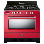


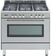
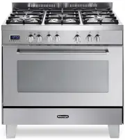
 DeLonghi DE6038MD
User Manual
DeLonghi DE6038MD
User Manual
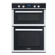
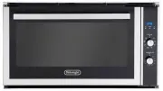
 DeLonghi DE608M
User Manual
DeLonghi DE608M
User Manual
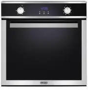
 DeLonghi DE62MPB
User Manual
DeLonghi DE62MPB
User Manual
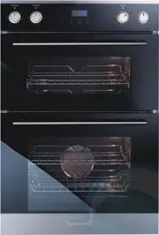
 DeLonghi DE906GWF
User Manual
DeLonghi DE906GWF
User Manual
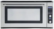
 DeLonghi DE908M
User Manual
DeLonghi DE908M
User Manual
 DeLonghi DE91PYROS
User Manual
DeLonghi DE91PYROS
User Manual
 DeLonghi DEF1407A
User Manual
DeLonghi DEF1407A
User Manual
 DeLonghi DEF1407S
User Manual
DeLonghi DEF1407S
User Manual
 DeLonghi DEF605E
User Manual
DeLonghi DEF605E
User Manual
 DeLonghi DEF605GW
User Manual
DeLonghi DEF605GW
User Manual
 DeLonghi DEF905EX1
User Manual
DeLonghi DEF905EX1
User Manual
 DeLonghi DEF905GW1X1
User Manual
DeLonghi DEF905GW1X1
User Manual
 DeLonghi DEF908S
User Manual
DeLonghi DEF908S
User Manual
 DeLonghi DEFL605E
User Manual
DeLonghi DEFL605E
User Manual
 DeLonghi DEFL605G
User Manual
DeLonghi DEFL605G
User Manual
 DeLonghi DEFP907S
User Manual
DeLonghi DEFP907S
User Manual
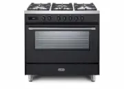
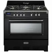 DeLonghi DEFV908BK
User Manual
DeLonghi DEFV908BK
User Manual
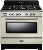 DeLonghi DEFV908CR
User Manual
DeLonghi DEFV908CR
User Manual
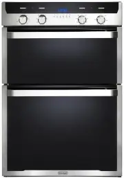 DeLonghi DEL6038D
User Manual
DeLonghi DEL6038D
User Manual
 DeLonghi DEL604M
User Manual
DeLonghi DEL604M
User Manual