Page 2 - PRODUCT LABEL; codes and specifications:
2 Dear Customer, Thank you for having purchased and given your preference to our product. The safety precautions and recommendations reported below are for your own safety and that of others. They will also provide a means by which to make full use of the features offered by your appliance. Please k...
Page 3 - IMPORTANT SAFETY PRECAUTIONS AND RECOMMENDATIONS; professionally qualified technician.; This film must be removed before using the; ■ IMPORTANT: The use of suitable protective clothing/gloves is
3 IMPORTANT SAFETY PRECAUTIONS AND RECOMMENDATIONS IMPORTANT: This appliance is designed and manufactured solely for the cooking of domestic (household) food and is not suitable for any non domestic application and therefore should not be used in a commercial environment. The appliance guarantee wil...
Page 4 - ■ WARNING: Ensure that the appliance is switched off before
4 ■ Do not operate your appliance by means of an external timer or separate remote-control system. ■ Do not carry out cleaning or maintenance operations on the appliance without having previously disconnected it from the electric power supply. ■ WARNING: Ensure that the appliance is switched off bef...
Page 7 - INSTALLATION; This appliance shall only be serviced by authorised personnel.; LOCATION; exceed the height of the cooktop.; The appliance must be housed in heat resistant units.
7 INSTALLATION CAUTION: ■ This appliance must be installed in accordance with these installation instructions. ■ This appliance shall only be serviced by authorised personnel. ■ This appliance is to be installed only by an authorised person in compliance with the current electrical regulations and i...
Page 8 - Figure 1
8 Figure 1 Cooker overall dimensions [mm] ■ height: min 850 - max 900 ■ width: 600 ■ depth: 600 45 0 m m 50 mm 65 0 m m 500 mm
Page 9 - Area for; ELECTRIC CONNECTION; Figure 2; FITTING THE ADJUSTABLE FEET; the fitting of the feet.; LEVELLING THE COOKER; Figure 4
9 min 270 mm max 320 mm (depending on feet height adjustment) Dotted line showing the position of the cooker when installed Area for ELECTRIC connection ELECTRIC CONNECTION Figure 2 FITTING THE ADJUSTABLE FEET The adjustable feet must be fitted to the base of the cooker before use (figs. 3, 4). Rest...
Page 10 - MOVING THE COOKER; Figure 5a
10 MOVING THE COOKER WARNING: When raising cooker to upright position always ensure two people carry out this manoeuvre to prevent damage to the adjustable feet (fig. 5a). WARNING - Be carefull: Do not lift the cooker by the door handle when raising to the upright position (fig. 5b). WARNING: When m...
Page 11 - screws of the anti-tilt bracket have to be fitted.
11 ANTI-TILT BRACKET Important! To restrain the appliance and prevent it tipping accidentally, fit a bracket to its rear to fix it securely to the wall. Make sure you also fit the supplied lock pin to the anti-tilt bracket. To fit the anti-tilt bracket: 1. After you have located where the cooker is ...
Page 12 - ELECTRICAL REQUIREMENTS; the load specified on the plate.; electrical regulations.
12 ELECTRICAL REQUIREMENTS ■ The appliance must be connected to the mains checking that the voltage corresponds to the value given in the rating plate and that the electrical cable sections can withstand the load specified on the plate. ■ A suitable disconnection switch must be incorporated in the p...
Page 13 - CONNECTION OF THE POWER SUPPLY CABLE; Unscrew the screw “; VOLTAGE AND POWER CONSUMPTION; suitably qualified person.; Figure 7
13 CONNECTION OF THE POWER SUPPLY CABLE Important! This cooker must be connected to the electricity supply only by an authorised person. ■ Unhook the terminal board cover by inserting a screwdriver into the two hooks “ A ” (fig. 7). ■ Unscrew the screw “ D ” and open completely the cable clamp “ E ”...
Page 14 - Figure 8; PE
14 230 V ~ 1 2 3 5 4 N L2 PE L1 G F D E 1 2 3 5 4 PE N L1 L2 G F D E 400 V 2N ~ 1 2 3 5 4 PE N L1 L2 L3 G F D E 400 V 3N ~ Figure 8 Figure 10 Figure 9 PE N (L 2 ) L 1 230 V 1 2 3 4 5 1 2 3 4 5 1 2 3 4 5 PE PE 400 V 3N 400 V 2N N L 1 L 2 N L 1 L 3 L 2 220-240 V ac 380-415 V 2N ac 380-415 V 3N ac 220-...
Page 15 - ELECTRIC DIAGRAM; Optional
15 ELECTRIC DIAGRAM TL S2 T F2 F4 F3 F5 P1 P2 P4 H H H S S S 2 2 2 4 4 4 S1 S1 S1 S1 S2 S2 S2 S2 4 4 4 4 P1 P1 P1 P1 P2 P2 P2 P2 2 2 2 2 P3 4 4A H S 2 4a 4 2 5 3 1 M TM C G S V S1 LF CF F1 TL 1 6 1a 6a 4 9 4a 9a 3 8 3a 8a 2 7 2a 7a 5 10 11 5a 10 a 11 a 45 0V PA 44 4 TB Optional CR Figure 12
Page 16 - ELECTRIC DIAGRAM KEY
16 ELECTRIC DIAGRAM KEY F1 Oven switch F2/5 Radiant heaters energy regulators F4 Double radiant heaters energy regulators LF Oven lamp TM Oven thermostat TL Thermal overload C Top element G Grill element S Bottom element CIR Circular element V Fan CR Residual heat Lamp CF Cooling fan S1 Thermostat p...
Page 17 - USE AND CARE; Do NOT modify this appliance.; USING THE OVEN FOR THE FIRST; The rack must be fitted so that the
17 USE AND CARE CAUTION: ■ This appliance must be used only for the task it has explicitly been designed for, that is for domestic cooking of foodstuffs. Any other form of usage is to be considered as inappropriate and therefore dangerous. ■ Do NOT place combustible materials or products on this app...
Page 18 - GREASE FILTER (OPTIONAL COMPONENT, CAN BE PURCHASED; when meat is being roasted.; Clean the filter after any cooking!; the oven performance.
18 Figure 15 GREASE FILTER (OPTIONAL COMPONENT, CAN BE PURCHASED SEPARATELY) ■ A special screen can be fitted at the back of the oven to catch grease particles, mainly when meat is being roasted. Slide in the grease filter on the back of the oven as in fig. 15. ■ Clean the filter after any cooking! ...
Page 19 - Oven temperature indicator light; CONTROL PANEL; The cooling fan motor switches ON/OFF depending on temperature.
19 Controls description 1. Front right cooking zone control knob2. Rear right cooking zone control knob3. Rear left cooking zone control knob4. Front left cooking zone control knob5. Oven function selector control knob6. Oven temperature control knob7. 60’ alarm control knob Pilot lamp 8. Oven tempe...
Page 20 - VITROCERAMIC HOB; VITROCERAMIC COOKING HOB; Hi-light cooking zone
20 Figure 17 VITROCERAMIC HOB VITROCERAMIC COOKING HOB 1. Hi-light cooking zone Ø 145 mm 1200 W (230V) 2. Double Hi-light cooking zone Ø 210/120 mm 2200/750 W (230V) 3. Hi-light cooking zone Ø 180 mm 1800 W (230V) 4. Residual heat indicators Attention: Detach the appliance from the mains if the cera...
Page 21 - “HI-LIGHT” RADIANT ZONES; to; Do not cover the hob with aluminium foils.; HOW TO USE THE VITROCERAMIC HOB
21 1 2 3 4 5 6 7 8 9 10 11 12 The ceramic surface of the hob allows a fast transmission of heat in the vertical direction, from the heating elements underneath the ceramic glass to the pans set on it. The heat does not spread in a horizontal direction, so that the glass stays “cool” at only a few ce...
Page 22 - “HI-LIGHT” DOUBLE RADIANT ZONE; Note: if you leave the knob at the; DOUBLE ZONE
22 1 2 3 4 5 6 7 8 9 10 11 12 Second element “HI-LIGHT” DOUBLE RADIANT ZONE The heating element is formed of a coil of resistant material which reaches the working temperature quickly. Operation of the cooking zone is controlled by a continuous energy regulator from 1 to 12 (maximum temperature) (fi...
Page 23 - SAFETY HINTS; has been switched off.; HOBS BECOME VERY HOT WITH USE, AND RETAIN THEIR HEAT FOR A LONG; DO NOT USE GLASSWARE ON CERAMIC HOBS.
23 SAFETY HINTS 1. Never put cooking foil or plastic materials on the ceramic surface when the hob is hot.2. Make sure that the hob is clean before you use it.3. Always ensure that the base of your saucepan is clean and dry before placing on the hob. 4. The glass-ceramic surface and pans must be cle...
Page 25 - ECONOMIC COOKING; minutes before you finish cooking.; Temperature control knob; Elements usage table
25 Knob setting TYPE OF COOKING 0 Switched OFF 1 2 For melting operations (butter, chocolate). 2 3 4 To maintain food hot and to heat small quantities of liquid (sauces, eggs). 4 5 6 To heat bigger quantities; to whip creams and sauces (vegetables, fruits, soups). 6 7 Slow boiling, i.e.: boiled meat...
Page 26 - Cast Iron
26 COOKWARE: It is very important that the pans used on the hobs are made of a suitable material and have the correct base as follows: ■ The base should be flat and smooth. ■ Any rough part on the pan base could scratch the hob surface. ■ Choose pans which are the same size as the hotplates and with...
Page 27 - COOKING WITH PLURIFUNCTION OVEN; Attention: The oven door becomes; GENERAL FEATURES; Upon first use, it is advisable to operate the; tray on the base of the oven chamber.; OPERATING PRINCIPLES; PLURIFUNCTION oven are obtained in the; a. by normal convection
27 COOKING WITH PLURIFUNCTION OVEN Attention: The oven door becomes very hot during operation. Keep children away. GENERAL FEATURES As its name indicates, this is an oven that presents particular features from an operational point of view. In fact, it is possible to insert 8 different programs to sa...
Page 28 - THERMOSTAT KNOB; program and the thermostat knob onto the desired temperature.; FUNCTION SELECTOR KNOB; By turning the knob onto this setting we light the oven cavity.; TRADITIONAL CONVECTION COOKING; position with the thermostat knob.
28 THERMOSTAT KNOB (fig. 24) To turn on the heating elements of the oven, set the function selector knob on the desired program and the thermostat knob onto the desired temperature. To set the temperature, it is necessary to make the knob indicator meet the chosen number. The elements will turn ON o...
Page 29 - For cooking hints, see the chapter “USE OF THE GRILL”.; VENTILATED GRILL COOKING; Use with the oven door closed; For correct use see chapter “GRILLING AND COOKING AU GRATIN”.
29 LOWER HEATING ELEMENT Only the lower element is switched on. Heat is distributed by natural convection. The thermostat can be set between 40°C and the maximum position with the thermostat knob. Recommended for: This mode is particularly suitable to complete cooking of dishes that require higher t...
Page 31 - COOKING ADVICE; The external parts of the appliance become hot during operation.; OVEN COOKING; The MULTIFUNCTION oven set on position
31 COOKING ADVICE The external parts of the appliance become hot during operation. Keep children well out of reach. OVEN COOKING Before introducing the food, preheat the oven to the desired temperature. For a correct preheating operation, it is advisable to remove the tray from the oven and introduc...
Page 32 - ROASTING; To obtain classical roasting, it is necessary to remember:; USE OF THE GRILL; Preheat the oven for about 5 minutes.; GRILLING AND COOKING “AU GRATIN”; Set the temperature knob; between 50°C and 225°C maximum; simply place the food on the grid.; Grilling with the oven door closed.; LEAVENING FUNCTION
32 ROASTING To obtain classical roasting, it is necessary to remember: ■ that it is advisable to maintain a temperature between 180 and 200°C. ■ that the cooking time depends on the quantity and the type of foods. USE OF THE GRILL Preheat the oven for about 5 minutes. Introduce the food to be cooked...
Page 33 - RECOMMENDED COOKING TEMPERATURE; Victoria sandwich
33 RECOMMENDED COOKING TEMPERATURE Food °C °F Gas Mark Shelf Position* Cooking Time (approx) CAKES Victoria sandwich 190 375 5 2 or 3 20-25 mins Small cakes/buns 190 375 5 1 and 2 15-20 mins Maidera cake 180 350 4 2 or 3 20 mins Fruit cake 170 325 3 3 1 3/4 hours Rich fruit cake 150 300 2 3 or 4 2 1...
Page 34 - MINUTE COUNTER; The minute counter is a timed acoustic; IMPORTANT WARNING: This is only a; HOW TO USE THE 60 MINUTES MECHANICAL ALARM
34 MINUTE COUNTER The minute counter is a timed acoustic warning device which can be set for a maximum of 60 minutes. The knob (fig. 27) must be rotated clockwise as far as the 60 minute position and then set to the required time by rotating it anticlockwise. IMPORTANT WARNING: This is only a mechan...
Page 35 - GENERAL ADVICE; and disconnected from the electrical power supply.; ENAMELLED PARTS; Dry preferably with a microfibre or soft cloth.; PRINTED SURFACES; irreparably damage the surface.; CLEANING THE CERAMIC HOB; CLEANING AND MAINTENANCE
35 GENERAL ADVICE ■ Before you begin cleaning, you must ensure that the appliance is switched off and disconnected from the electrical power supply. ■ It is advisable to clean when the appliance is cold and especially when cleaning the enamelled parts. ■ Avoid leaving alkaline or acidic substances (...
Page 36 - become increasingly difficult to remove.; This is especially true in the case of; by the heat away from the top: plastic; avoid damaging the seal at the edges of the glass ceramic surface.; INSIDE OF OVEN; Do not store flammable material in the oven.; GRILL HEATING ELEMENT
36 ■ Dust, fat and liquids from food that has boiled over must be removed as soon as possible. ■ If they are allowed to harden they become increasingly difficult to remove. This is especially true in the case of sugar/syrup mixtures which could permanently pit the surface of the hob if left to burn ...
Page 37 - REPLACING THE OVEN LIGHT; having the following specifications; contamination from your fingers can; Refit the protective cover “; DRAWER; Do not store flammable material in the oven or in the drawer.
37 REPLACING THE OVEN LIGHT WARNING: Ensure the appliance is switched off before replacing the lamp to avoid the possibility of electric shock. ■ Let the oven cavity and the heating elements to cool down. ■ Disconnect the appliance from the electrical power supply. ■ Remove the protective cover “ C ...
Page 38 - REMOVING THE OVEN DOOR; Open the door to the full extent (fig.
38 REMOVING THE OVEN DOOR The oven door can easily be removed as follows: • Open the door to the full extent (fig. 31). • Open the lever “ A ” completely on the left and right hinges (fig. 32). • Hold the door as shown in fig. 30. • Gently close the door until left and right hinge levers “ A ” are h...
Page 39 - Note; REFIT THE DOOR
39 REMOVING AND REPLACING THE INNER DOOR GLASS PANE FOR CLEANING If you wish to clean the inner glass of the door, make sure you follow the precautions and instructions very carefully. Replacing the glass pane and the door incorrectly may result in damage to the oven and may void your warranty. IMPO...
Page 40 - The oven door is fitted with no. 2 panes:; Remove the inner pane:
40 REMOVING THE INNER PANE OF GLASS The oven door is fitted with no. 2 panes: • no. 1 outside; • no. 1 inner. To clean all panes on both sides it is necessary to remove the inner pane as follows: 1. Lock the door open: • Fully open the oven door (fig. 38). • Fully open the lever “ A ” on the left an...
Page 42 - SERVICE AND MAINTENANCE; SERVICING THE APPLIANCE; Authorised Delonghi Service Agent:; Servicing shall be carried out only by authorized personnel.; TROUBLESHOOTING; nearest Authorised Delonghi Service Agent.
42 SERVICE AND MAINTENANCE SERVICING THE APPLIANCE Service may be obtained by contacting our Customer Service Centre to locate the nearest Authorised Delonghi Service Agent: Servicing shall be carried out only by authorized personnel. The appliance shall not be modified. TROUBLESHOOTING If you exper...


 DeLonghi DE6038MD
User Manual
DeLonghi DE6038MD
User Manual
 DeLonghi DE608M
User Manual
DeLonghi DE608M
User Manual
 DeLonghi DE62MPB
User Manual
DeLonghi DE62MPB
User Manual
 DeLonghi DE906GWF
User Manual
DeLonghi DE906GWF
User Manual
 DeLonghi DE908M
User Manual
DeLonghi DE908M
User Manual
 DeLonghi DE91PYROS
User Manual
DeLonghi DE91PYROS
User Manual
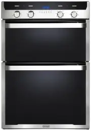
 DeLonghi DEF1407A
User Manual
DeLonghi DEF1407A
User Manual
 DeLonghi DEF1407S
User Manual
DeLonghi DEF1407S
User Manual
 DeLonghi DEF605E
User Manual
DeLonghi DEF605E
User Manual
 DeLonghi DEF605GW
User Manual
DeLonghi DEF605GW
User Manual
 DeLonghi DEF905EX1
User Manual
DeLonghi DEF905EX1
User Manual
 DeLonghi DEF905GW1X1
User Manual
DeLonghi DEF905GW1X1
User Manual
 DeLonghi DEF908S
User Manual
DeLonghi DEF908S
User Manual
 DeLonghi DEFL605G
User Manual
DeLonghi DEFL605G
User Manual
 DeLonghi DEFP907S
User Manual
DeLonghi DEFP907S
User Manual
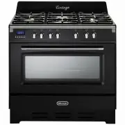 DeLonghi DEFV908BK
User Manual
DeLonghi DEFV908BK
User Manual
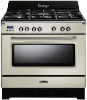 DeLonghi DEFV908CR
User Manual
DeLonghi DEFV908CR
User Manual
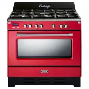 DeLonghi DEFV908R
User Manual
DeLonghi DEFV908R
User Manual
 DeLonghi DEL6038D
User Manual
DeLonghi DEL6038D
User Manual
 DeLonghi DEL604M
User Manual
DeLonghi DEL604M
User Manual