Honeywell RLV3150A1004/E - User Manual
Honeywell RLV3150A1004/E Thermostat – User Manual, read for free online in PDF format. We hope this helps you resolve any issues you may have. If you have further questions, please contact us through the contact form.


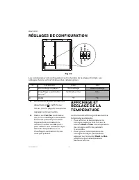
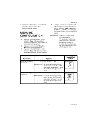
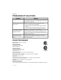

Table of Contents:
- Page 2 – WARNING
- Page 3 – WIRING
- Page 4 – CONFIGURATION SETTINGS
- Page 6 – SPECIFICATIONS; -YEAR LIMITED WARRANTY
- Page 7 – CUSTOMER ASSISTANCE
- Page 9 – GUIDE DE L’UTILISATEUR; THERMOSTAT ÉLECTRONIQUE; APPLICATION; COMMANDES ET AFFICHAGE
- Page 10 – AVERTISSEMENT
- Page 11 – CÂBLAGE; Installation à 2 fils
- Page 12 – RÉGLAGES DE CONFIGURATION
- Page 15 – GARANTIE LIMITÉE D'UN AN
- Page 16 – SERVICE À LA CLIENTÈLE
USER GUIDE
33-00209EF-05
RLV3150
ELECTRONIC THERMOSTAT
APPLICATION
This thermostat is designed to control
an electric heating system such as a
baseboard heater, a convector or a fan-
forced heater.
The thermostat
cannot
be used with the
following:
• a resistive load under 2 A
• a resistive load over 12.5 A
• systems driven by a contactor or a
relay (inductive load)
• central heating systems
Supplied Parts
• One (1) thermostat
• Two (2) 6-32 mounting screws
• Two (2) solderless connectors
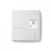
CONTROLS AND DISPL AY
Fig. 1.
Backlit Screen
Up button
Temperature
Heating intensity
indicator (the image
disappears when
heating is off)
Appears when the
setpoint is displayed
Appears when the
thermostat is configured
for a fan-forced heater
(see page 3)
The settings are locked
Down button
"Loading the manual" means you need to wait until the file loads and becomes available for online reading. Some manuals are very large, and the time they take to appear depends on your internet speed.
Summary
RLV3150 33-00209EF—05 2 INSTALLATION GUIDELINES WARNING TURN OFF POWER TO THE HEATING SYSTEM AT THE MAIN POWER PANEL TO AVOID ELECTRICAL SHOCK. • The installation must comply with local electrical codes. • Do NOT install the thermostat in an area where it can be exposed to water or rain. • Avoid loc...
RLV3150 3 33-00209EF—05 NOTE: If there is a protective film or sticker on the thermostat’s screen, peel it off. 6. Apply power to the heating sys-tem. Verify the installation by checking that the heating system can be turned On by raising the setpoint using the Up button or turned Off by lowering th...
RLV3150 33-00209EF—05 4 CONFIGURATION SETTINGS Fig. 5. Configuration switches are on the back of the faceplate. Factory settings are inside gray cells. 1. The thermostat buttons are dis- abled and appears on the screen (see page 1) when the set- tings are locked. 2. Place at Fan Yes if you have a fa...