Honeywell AT72D1683/Z - User Manual
Honeywell AT72D1683/Z Thermostat – User Manual, read for free online in PDF format. We hope this helps you resolve any issues you may have. If you have further questions, please contact us through the contact form.


Table of Contents:
- Page 2 – INSTALLATION; When Installing This Product...; WARNING; Mounting the AT20A and AT40A
- Page 3 – Mounting the AT72D Transformer.; Clamp Mounting Using Junction Box Knockout
- Page 5 – Mounting the AT87 Transformer; Plate Mounting; Mounting the AT88 Transformer.
- Page 6 – WIRING
- Page 7 – NOTICE D'INSTALLATION; Transformateurs AT; APPLICATION
- Page 8 – Avant d'installer ce produit...; AVERTISSEMENT; Montage des transformateurs AT20A et
- Page 9 – Montage du transformateur AT72D; Montage sur socle; Montage sur plaque
- Page 11 – Montage du transformateur AT87; Montage du transformateur AT88
- Page 12 – CÂBLAGE; VÉRIFICATION
® U.S. Registered Trademark
Copyright © 2002 Honeywell • All Rights Reserved
INSTALLATION INSTRUCTIONS
69-1641EF
AT20, AT40, AT72D, AT87, AT88
AT Transformers
APPLICATION
The AT20, AT40, AT72, AT87 and AT88 TRADELINE®
Transformers are step-down transformers used primarily
for powering 24 Vac control systems. They can be used
in any 24 Vac application that does not exceed the
transformer volt-ampere (VA) rating.
The TRADELINE® Transformers will replace all
equivalent Honeywell and competitive transformers with
similar primary voltage requirements, equal or smaller VA
ratings and similar mounting configurations.
Transformer voltage ratings (primary and secondary),
wiring connection type, and fusing are listed in Table 1.
The transformers are Underwriters Laboratories Inc.
component recognized and Canadian Standards
Association listed and meet NEC Class 2 not wet, Class
3 wet requirements as specified by NEMA Standard
DC-20.
SPECIFICATIONS
Models:
See Table 1.
Table 1. Transformer Model and Electrical Specifications.
a
Transformer complies with 24 volt NEMA Standard DC-20.
b
Available with female quick-connect terminals on all leadwires.
c
Thermal fuses in primary on 208V/240V models for overload protection.
Model
Primary
Secondary
Output at
100 Percent
Power
Rating
Overload
Protection
Voltage and
Frequency
Wiring Connection
Voltage
Wiring Connection
AT20
a
120 Vac, 50/60 Hz
Two 9 in. (229 mm)
leadwires
24 Vac
Two 9 in. (229 mm)
leadwires
20 VA
Energy
Limited
c
AT40
a
120 Vac, 50/60 Hz
40 VA
240 Vac, 50/60 Hz
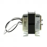
AT72D
a
120 Vac, 50/60 Hz
Two screw
terminals
240 Vac, 50/60 Hz
Three 9 in. (229
mm) leadwires
AT87A
a
120 Vac, 50/60 Hz
Two 13 in. (330 mm)
leadwires
50 VA
208 Vac, 50/60 Hz
240 Vac, 50/60 Hz
AT88A
120Vac, 50/60 Hz
Two 12 in. (305 mm)
leadwires
24 Vac
Two 12 in. (305
mm) leadwires
75 VA
Fuse in
secondary
208/240 Vac, 50/60
Hz
400 Vac, 50/60 Hz
480 Vac, 50/60 Hz
b
"Loading the manual" means you need to wait until the file loads and becomes available for online reading. Some manuals are very large, and the time they take to appear depends on your internet speed.
Summary
AT20, AT40, AT72D, AT87, AT88 AT TRANSFORMERS 69-1641EF 2 INSTALLATION When Installing This Product… 1. Read these instructions carefully. Failure to follow them could damage the product or cause a hazardous condition. 2. Check the ratings given in the instructions and on the product to make sure th...
AT20, AT40, AT72D, AT87, AT88 AT TRANSFORMERS 3 69-1641EF Mounting the AT72D Transformer. Mount the transformer to meet the application. Use one of the methods illustrated. The transformer can be mounted in any position. Foot Mounting. 1. Discard mounting plate. 2. Use screws or bolts through slots ...
AT20, AT40, AT72D, AT87, AT88 AT TRANSFORMERS 5 69-1641EF Fig. 7. Secure plate to transformer with mounting screw. Fig. 8. Location of mounting holes. Mounting the AT87 Transformer Foot Mounting (Fig. 22) Use screws or bolts through slots in the mounting feet to fasten the transformer to the mountin...