Page 2 - GROUNDING INSTRUCTIONS; DO NOT USE AN EXTENSION CORD; RADIO FREQUENCY INTERFERENCE; SAVE THESE INSTRUCTIONS!
IMPORTANT SAFETY INSTRUCTIONSREAD AND FOLLOW ALL SAFETY INSTRUCTIONS GROUNDING INSTRUCTIONS This appliance must be grounded. In the event of an electrical short circuit, grounding reduces the risk of electrical shock by providing an escape wire for the electrical current. This appliance is equipped ...
Page 3 - SAFETY INSTRUCTIONS; return it to its point of purchase or contact consumer care.
IMPORTANT SAFETY INSTRUCTIONSREAD AND FOLLOW ALL SAFETY INSTRUCTIONS SAVE THESE INSTRUCTIONS! SAFETY INSTRUCTIONS • Ensure that component parts are replaced with like components and that servicing is done by factory authorized service personnel, to minimize the risk of possible ignition due to incor...
Page 4 - SAFETY - SUPERHEATED LIQUID; checked before serving in order to avoid burns.
IMPORTANT SAFETY INSTRUCTIONSREAD AND FOLLOW ALL SAFETY INSTRUCTIONS SAVE THESE INSTRUCTIONS! SAFETY - SUPERHEATED LIQUID Liquids are able to be overheated beyond the boiling point without appearing to be boiling due to the surface tension of the liquid. Visible bubbling will not always be present w...
Page 5 - INSTALLATION INSTRUCTIONS; PARTS INCLUDED; INSTALLATION ACCESSORIES; PART
• Remove all packing materials from the inside and outside of the appliance. Do not remove the cardboard mica sheet covering the magnetron. • Check the appliance for damage before using, such as a misaligned or bent door, damaged door seals, broken or loose door hinges or latches, or dents inside th...
Page 6 - REQUIRED TOOLS; • The space between the cabinets must be 30”
INSTALLATION INSTRUCTIONS 17 - 1/8 " 3 0 " min. 2 " 24" 66" min REQUIRED TOOLS Filler blocks or scrap wood pieces (for top cabinet spacing in recessed boom cabinet installaons, if needed) Pencil #1 and #2 Phillips screwdrivers Ruler or tape measurestraight edge Carpenter square (...
Page 8 - USING THE INSTALLATION TEMPLATE; Flat bottomed cabinet; : The top of the template; Framed recessed cabinet; The top of the template should align; Aligning the center line of the rear wall; Measure the space where the
INSTALLATION INSTRUCTIONS At least 24 .&87287)25+25,=217$/ 2876,'((;+$867 72('*( 5($5:$//7(03/$7( 0,1,080:,'7+5(48,5(' &$87,21,)(;+$867$'$3725,6326,7,21('2876,'( &87+2/(7+528*+5($5:$//)25(;+$867$'$3725 5(&200(1'('',0(16,21ˈ*5($6(/$'(1$,5:,// ',6&+$5*(,172+286(6758&785( IN THE...
Page 9 - TEMPLATE DAMAGED OR UNUSABLE
INSTALLATION INSTRUCTIONS TEMPLATE DAMAGED OR UNUSABLE If the template arrives damaged or cannot be used, measure and mark the wall with these dimensions. Remember that the microwave must be level. The bottom edge of the mounting plate must be 17 1/8” (43.5 cm) from the bottom edge of the upper cabi...
Page 10 - HOOD EXHAUST; Roof cap
INSTALLATION INSTRUCTIONS HOOD EXHAUST This microwave is designed for adaptation to three types of ventilation: outside top exhaust, outside back exhaust and non-venting ductless recirculation. Use the following duct instructions if the appliance will be vented to the outside. For satisfactory air m...
Page 11 - DUCT LENGTH CALCULATOR
DUCT PIECES EQUIVALENT LENGTH X NUMBER USED = EQUIVALENT LENGTH Rectangular to round transition adapter 5 ft X ( ) = ft Wall cap 40 ft X ( ) = ft Round 90° elbow 10 ft X ( ) = ft Round 45° elbow 5 ft X ( ) = ft Rectangular 90° elbow 25 ft X ( ) = ft Rectangular 45° elbow 5 ft X ( ) = ft Roof cap 24 ...
Page 12 - INSTALLATION INSTRUCTIONS - OUTSIDE TOP EXHAUST; Install the mounting plate
INSTALLATION INSTRUCTIONS - OUTSIDE TOP EXHAUST Use these instructions if the appliance will be vented to the outside through the top of the appliance. Install the mounting plate Use a 5/8” drill to make two holes that will enter the drywall. Use a 3/16” drill to make a hole that will enter a wall s...
Page 13 - Screw; Check for proper damper operation; Using the top cabinet template
Damper Back of microwave Blower Plate Screw Guide Blower Plate Guide Check for proper damper operation Place the microwave in its upright position with the top of the appliance facing up. Make sure the tape securing the damper is removed and the damper pivots easily before mounting the microwave. At...
Page 14 - Mounting the microwave oven; Lift the microwave, tilt it forward and hook the
1 2 3 nylon grommet metal cabinet power cord power cordhole Turn two full turns on each screw. self-aligningmachine screw washer Cabinet Front Equivalent to Depth of CabinetRecess Cabi Sel f-Aligning machine Screw Microwave Oven top Washer Filler Block Mounting the microwave oven Two people should b...
Page 15 - Install grease fi lters; Extend the house duct down to connect to the exhaust adapter.
INSTALLATION INSTRUCTIONS - OUTSIDE TOP EXHAUST Install grease fi lters Slide the grease fi lters into the openings in the bottom of the microwave until they click into place. The appliance should not be operated without the grease fi lters installed. Connecting ductwork Adjust the exhaust adapter insi...
Page 16 - INSTALLATION INSTRUCTIONS - OUTSIDE BACK EXHAUST
INSTALLATION INSTRUCTIONS - OUTSIDE BACK EXHAUST Use these instructions if the appliance will be vented to the outside through the back of the appliance. Cut a 12” x 4” square hole in the rear wall for the outside exhaust. Follow the instructions included on the rear template. Install the mounting p...
Page 17 - Part“A”
1 2 3 4 5 Back ofMicrowave Blower Plate screw Blower motor screw B lowe r Motor Part“A” Blower Motor screw Adaptor Back of Microwave Guide Guide Blower Motor screw Blower Plate Adaptor Microwave Back of Using the top cabinet template There are instructions on the top cabinet template that detail how...
Page 21 - Adapting blower for recirculating exhaust
1 2 3 Blower Plate screw Blower motor screw Microwave Back of B lowe r Motor Adapting blower for recirculating exhaust 1. Remove the screws that secure the blower motor. Lift up the blower plate. 2. Pull out the blower unit. Be careful not to stretch the wires and make sure the wires do not get pinc...
Page 22 - nylon grommet
Mounting the microwave oven Two people should be used to install the microwave. Do not grip or use the handle during installation. If the surrounding cabinets are metal, use the nylon grommet around the power cord hole to prevent damage to the cord. When mounting the microwave, thread the power cord...
Page 23 - Charcoal fi lter; Remove the two screws securing the louver on
Charcoal fi lter The charcoal fi lter should be used in non-vented, recirculating installations. The fi lter should be changed every 6 to 12 months depending on use. 1. Remove the two screws securing the louver on the front of the microwave. 2. Remove the used charcoal fi lter.3. Install the new charcoa...
Page 24 - CONSERVEZ CES INSTRUCTIONS !; INSTRUCTIONS DE MISE À LA TERRE; AVERTISSEMENT; INTERFÉRENCES DE FRÉQUENCE RADIO
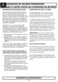
CONSIGNES DE SÉCURITÉ IMPORTANTESLIRE ET SUIVRE TOUTES LES CONSIGNES DE SÉCURITÉ CONSERVEZ CES INSTRUCTIONS ! INSTRUCTIONS DE MISE À LA TERRE Cet appareil doit être mis à la terre. En cas de court-circuit électrique, la mise à la terre réduit le risque de choc électrique en fournissant un fi l d’écha...
Page 25 - CONSIGNES DE SÉCURITÉ
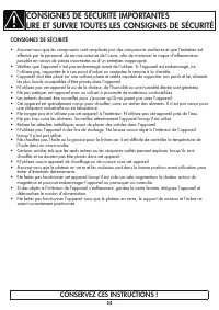
CONSIGNES DE SÉCURITÉ • Assurez-vous que les composants sont remplacés par des composants similaires et que l’entretien est effectué par le personnel de service autorisé de l’usine, afi n de minimiser le risque d’infl ammation possible en raison de pièces incorrectes ou d’un entretien inapproprié. • V...
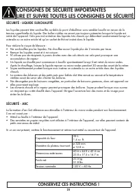
Page 26 - SÉCURITÉ - LIQUIDE SURCHAUFFÉ
SÉCURITÉ - LIQUIDE SURCHAUFFÉ Les liquides peuvent être surchauffés au-delà du point d’ébullition sans sembler bouillir en raison de la tension superfi cielle du liquide. Des bulles visibles ne seront pas toujours présentes lorsque le liquide est retiré de l’appareil. Cela pourrait entraîner des liqu...
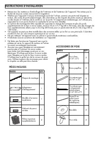
Page 27 - INSTRUCTIONS D’INSTALLATION; PIÈCES INCLUSES; ACCESSOIRES DE POSE; PARTIE
• Retirez tous les matériaux d’emballage de l’intérieur et de l’extérieur de l’appareil. Ne retirez pas la feuille de mica en carton recouvrant le magnétron. • Vérifi ez que l’appareil n’est pas endommagé avant de l’utiliser, comme une porte mal alignée ou tordue, des joints de porte endommagés, des ...
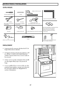
Page 28 - OUTILS REQUIS; • L’espace entre les armoires doit être de 30” de
INSTRUCTIONS D’INSTALLATION 17 - 1/8 " 3 0 " min. 2 " 24" 66" min OUTILS REQUIS niveau scie (sabre, trou ou trou de serrure) détecteur de montants bord à bord ou un marteau (facultaf) du ruban adhésif et du ruban de masquage lunees de sécurité des gants tournevis Phillipa #1 et #...
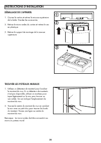
Page 29 - DÉBALLAGE DE L’APPAREIL; Ouvrez le carton et retirez la mousse supérieure; TROUVER LES POTEAUX MURAUX; Utilisez un détecteur de montant pour localiser
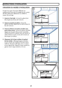
INSTRUCTIONS D’INSTALLATION DÉBALLAGE DE L’APPAREIL 1. Ouvrez le carton et retirez la mousse supérieure de la boîte. Gardez les accessoires. 2. Retirez le micro-ondes du carton et retirez le sac en plastique. 3. Retirez le support de montage de la mousse supérieure. 1 2 3 TROUVER LES POTEAUX MURAUX ...
Page 30 - UTILISATION DU MODÈLE D’INSTALLATION; Le haut du gabarit doit; Armoire inférieure encastrée encadrée avec; Le haut du gabarit doit être; Alignement de la ligne médiane du gabarit; Mesurez l’espace où le four
INSTRUCTIONS D’INSTALLATION At least 24 .&87287)25+25,=217$/ 2876,'((;+$867 72('*( 5($5:$//7(03/$7( 0,1,080:,'7+5(48,5(' &$87,21,)(;+$867$'$3725,6326,7,21('2876,'( &87+2/(7+528*+5($5:$//)25(;+$867$'$3725 5(&200(1'('',0(16,21ˈ*5($6(/$'(1$,5:,// ',6&+$5*(,172+286(6758&785( IN T...
Page 31 - MODÈLE ENDOMMAGÉ OU INUTILISABLE
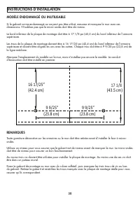
INSTRUCTIONS D’INSTALLATION 16 17/25” 17 1/8 9 9/25” (42.4 cm) (43.5 cm) (23.8 cm) 9 9/25” (23.8 cm) MODÈLE ENDOMMAGÉ OU INUTILISABLE Si le gabarit arrive endommagé ou ne peut pas être utilisé, mesurez et marquez le mur avec ces dimensions. N’oubliez pas que le micro-ondes doit être de niveau. Le bo...
Page 32 - ÉCHAPPEMENT DE LA HOTTE; Chapeau de toit
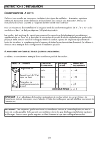
INSTRUCTIONS D’INSTALLATION ÉCHAPPEMENT DE LA HOTTE Ce four à micro-ondes est conçu pour s’adapter à trois types de ventilation : évacuation supérieure extérieure, évacuation arrière extérieure et recirculation sans conduit sans évacuation. Utilisez les instructions de conduit suivantes si l’apparei...
Page 33 - CALCULATEUR DE LONGUEUR DE CONDUIT
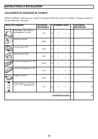
INSTRUCTIONS D’INSTALLATION PIÈCES DE CONDUITS LONGUEUR ÉQUIVALENTE X NOMBRE UTILISÉ = LONGUEUR ÉQUIVALENTE Adaptateur de transition rectangulaire à rond 5 ft X ( ) = ft Capuchon mural 40 ft X ( ) = ft Coude rond à 90° 10 ft X ( ) = ft Coude rond à 45° 5 ft X ( ) = ft Coude rectangulaire à 90° 25 ft...
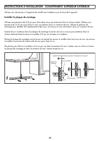
Page 34 - Installer la plaque de montage; INSTRUCTIONS D’INSTALLATION - ÉCHAPPEMENT SUPÉRIEUR EXTÉRIEUR
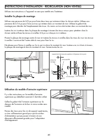
Utilisez ces instructions si l’appareil est ventilé vers l’extérieur par le haut de l’appareil. Installer la plaque de montage Utilisez une perceuse de 5/8 po pour faire deux trous qui entreront dans la cloison sèche. Utilisez une perceuse de 3/16 po pour faire un trou qui entrera dans un montant de...
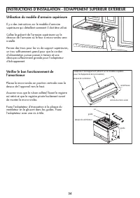
Page 35 - Utilisation du modèle d’armoire supérieure
amorsseur arrière du micro-onde plaque de venlateur plaque de venlateur guide guide vis adaptateur d'échappement (absent sur les modèles expédiés pour l'échappement de recirculaon) Vérifi er le bon fonctionnement de l’amortisseur Placez le micro-ondes en position verticale avec le dessus de l’apparei...
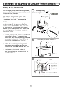
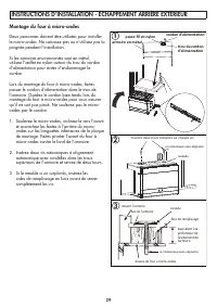
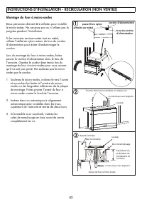
Page 36 - armoire en métal; Montage du four à micro-ondes; Insérez deux vis mécaniques à alignement
1 2 3 passe-fil en nylon armoire en métal cordon d'alimentaon trou du cordon d'alimentaon Tournez deux tours complets sur chaque vis. vis mécanique auto-alignante rondelle devant l'armoire équivalent à la profondeur de l'évidement de l'armoire bas de l'armoire dessus de four à micro-ondes bloc de rem...
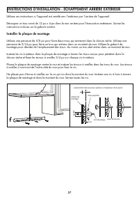
Page 38 - INSTRUCTIONS D’INSTALLATION - ÉCHAPPEMENT ARRIÈRE EXTÉRIEUR
Utilisez ces instructions si l’appareil est ventilé vers l’extérieur par l’arrière de l’appareil. Découpez un trou carré de 12 po x 4 po dans le mur arrière pour l’évacuation extérieure. Suivez les instructions incluses sur le gabarit arrière. Installer la plaque de montage Utilisez une perceuse de ...
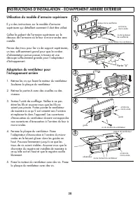
Page 39 - Parte “A”
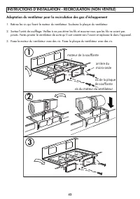
1 2 3 4 5 Parte “A” adaptateur guide guide plaque de venlateur adaptateur vis de la plaque de soufflante vis du moteur du venlateur moteur de la soufflante arrière du micro-onde arrière du micro-onde arrière du micro-onde vis du moteur du venlateur vis du moteur du venlateur Utilisation du modèle d’armo...
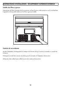
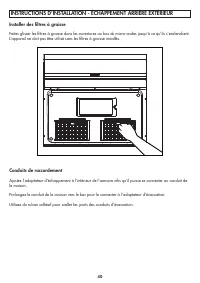
Page 45 - Filtre à charbon; Retirez les deux vis fi xant la grille à l’avant du; Installer des fi ltres à graisse; Recirculation d’air
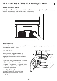
Filtre à charbon Le fi ltre à charbon doit être utilisé dans des installations de recirculation sans évacuation. Le fi ltre doit être changé tous les 6 à 12 mois selon l’utilisation. 1. Retirez les deux vis fi xant la grille à l’avant du four à micro-ondes. 2. Retirez le fi ltre à charbon usagé.3. Insta...
Page 46 - ¡GUARDA ESTAS INSTRUCCIONES!; INSTRUCCIONES DE PUESTA A TIERRA; ADVERTENCIA; : el uso inadecuado del enchufe; NO UTILICE UN CABLE DE EXTENSIÓN; INTERFERENCIA DE RADIOFRECUENCIA; • Reorientar la antena receptora de radio o; EVITE LA POSIBLE EXPOSICIÓN A ENERGÍA; • No intente operar el aparato con la puerta
¡GUARDA ESTAS INSTRUCCIONES! INSTRUCCIONES DE PUESTA A TIERRA Este aparato debe estar conectado a tierra. En caso de un cortocircuito eléctrico, la conexión a tierra reduce el riesgo de descarga eléctrica al proporcionar un cable de escape para la corriente eléctrica. Este electrodoméstico está equi...
Page 47 - LAS INSTRUCCIONES DE SEGURIDAD; para uso industrial o de laboratorio.
¡GUARDA ESTAS INSTRUCCIONES! LAS INSTRUCCIONES DE SEGURIDAD • Asegúrese de que las piezas de los componentes se reemplacen con componentes similares y que el servicio lo realice personal de servicio autorizado de fábrica, para minimizar el riesgo de una posible ignición debido a piezas incorrectas o...
Page 48 - SEGURIDAD - LÍQUIDO SOBRECALENTADO; Diámetro de la placa giratoria:
INSTRUCCIONES DE SEGURIDAD IMPORTANTESLEA Y SIGA TODAS LAS INSTRUCCIONES DE SEGURIDAD SEGURIDAD - LÍQUIDO SOBRECALENTADO Los líquidos pueden sobrecalentarse más allá del punto de ebullición sin que parezca que están hirviendo debido a la tensión superfi cial del líquido. No siempre habrá burbujas vis...
Page 49 - INSTRUCCIONES DE INSTALACIÓN; PIEZAS INCLUIDAS; ACCESORIOS DE INSTALACIÓN; PARTE
• Retire todos los materiales de embalaje del interior y exterior del aparato. No retire la hoja de mica de cartón que cubre el magnetrón. • Verifi que que el electrodoméstico no esté dañado antes de usarlo, como una puerta desalineada o doblada, sellos de la puerta dañados, bisagras o pestillos de l...
Page 50 - • El espacio entre los gabinetes debe ser de 30”
17 - 1/8 " 3 0 " min. 2 " 24" 66" min HERRAMIENTAS REQUERIDAS nivel (sable, agujero o ojo de cerradura) sierra guantes gafas protectoras cinta adhesiva y de enmascarar (para cortar el amorguador, si es necesario) jeras de hojalatero (para cortar planlla, si es necesario) jeras co...
Page 51 - DESEMBALAJE DEL APARATO; Abra la caja y retire la espuma superior de la
1 2 3 DESEMBALAJE DEL APARATO 1. Abra la caja y retire la espuma superior de la caja. Guarda los accesorios. 2. Retire el microondas de la caja y retire la bolsa de plástico. 3. Retire el soporte de montaje de la espuma superior. ENCONTRAR LOS MONTANTES DE LA PARED 1. Utilice un detector de montante...
Page 52 - USO DE LA PLANTILLA DE INSTALACIÓN; La parte superior de; Gabinete inferior empotrado enmarcado; La parte superior de la; Alineación de la línea central de la plantilla; Mida el espacio donde
At least 24 .&87287)25+25,=217$/ 2876,'((;+$867 72('*( 5($5:$//7(03/$7( 0,1,080:,'7+5(48,5(' &$87,21,)(;+$867$'$3725,6326,7,21('2876,'( &87+2/(7+528*+5($5:$//)25(;+$867$'$3725 5(&200(1'('',0(16,21ˈ*5($6(/$'(1$,5:,// ',6&+$5*(,172+286(6758&785( IN THE INSTALLATION INSTRUCTI O ...
Page 53 - PLANTILLA DAÑADA O INUTILIZABLE
16 17/25” 17 1/8 9 9/25” (42.4 cm) (43.5 cm) (23.8 cm) 9 9/25” (23.8 cm) INSTRUCCIONES DE INSTALACIÓN PLANTILLA DAÑADA O INUTILIZABLE Si la plantilla llega dañada o no se puede utilizar, mida y marque la pared con estas dimensiones. Recuerda que el microondas debe estar nivelado. El borde inferior d...
Page 54 - ESCAPE DE CAPO; Tapa de techo
INSTRUCCIONES DE INSTALACIÓN ESCAPE DE CAPO Este microondas está diseñado para adaptarse a tres tipos de ventilación: escape superior exterior, escape trasero exterior y recirculación sin conductos sin ventilación. Utilice las siguientes instrucciones de conductos si el aparato se ventilará hacia el...
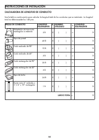
Page 55 - CALCULADORA DE LONGITUD DE CONDUCTO
PIEZAS DE CONDUCTO LONGITUD EQUIVALENTE X NÚMERO UTILIZADO = LONGITUD EQUIVALENTE Adaptador de transición rectangular a redondo 5 ft X ( ) = ft Tapa de pared 40 ft X ( ) = ft Codo redondo de 90° 10 ft X ( ) = ft Codo redondo de 45° 5 ft X ( ) = ft Codo rectangular de 90° 25 ft X ( ) = ft Codo rectan...
Page 56 - Instale la placa de montaje; INSTRUCCIONES DE INSTALACIÓN - ESCAPE SUPERIOR EXTERIOR
Use estas instrucciones si el electrodoméstico se ventilará hacia el exterior a través de la parte superior del electrodoméstico. Instale la placa de montaje Use un taladro de 5/8” para hacer dos agujeros que entrarán en el panel de yeso. Use un taladro de 3/16” para hacer un agujero que entre en un...
Page 57 - Usando la plantilla del gabinete superior
apagador parte trasera del microondas placa del soplador adaptador de escape (ausente en los modelos enviados para escape de recirculación) tornillo guía placa del soplador guía Usando la plantilla del gabinete superior Hay instrucciones en la plantilla del gabinete superior que detallan cómo debe u...
Page 58 - Montaje del horno de microondas; Levante el microondas, inclínelo hacia adelante; ojal de nailon
INSTRUCCIONES DE INSTALACIÓN - ESCAPE SUPERIOR EXTERIOR Montaje del horno de microondas Se deben utilizar dos personas para instalar el microondas. No agarre ni use el mango durante la instalación. Si los gabinetes circundantes son de metal, use la arandela de nailon alrededor del orifi cio del cable...
Page 59 - Instalar fi ltros de grasa; Use cinta adhesiva para sellar las juntas del conducto de escape.
INSTRUCCIONES DE INSTALACIÓN - ESCAPE SUPERIOR EXTERIOR Instalar fi ltros de grasa Deslice los fi ltros de grasa en las aberturas en la parte inferior del microondas hasta que encajen en su lugar. El aparato no debe funcionar sin los fi ltros de grasa instalados. Conexión de conductos Ajuste el adaptad...
Page 60 - INSTRUCCIONES DE INSTALACIÓN - ESCAPE EXTERIOR TRASERO
Use estas instrucciones si el electrodoméstico se ventilará hacia el exterior a través de la parte posterior del electrodoméstico. Corte un agujero cuadrado de 12” x 4” en la pared trasera para el escape exterior. Siga las instrucciones incluidas en la plantilla trasera. Instale la placa de montaje ...
Page 64 - INSTRUCCIONES DE INSTALACIÓN - RECIRCULACIÓN (SIN VENTILACIÓN)
Use these instructions if the appliance will not be vented to the outside. Instale la placa de montaje Use un taladro de 5/8” para hacer dos agujeros que entrarán en el panel de yeso. Use un taladro de 3/16” para hacer un agujero que entre en un montante de la pared. Utilice la plantilla de montaje ...
Page 65 - Adaptación del ventilador para el escape de recirculación
1 2 3 tornillo de la placa del venlador tornillo del motor del venlador parte trasera del microondas motor del venlador Adaptación del ventilador para el escape de recirculación 1. Retire los tornillos que aseguran el motor del ventilador. Levante la placa del ventilador. 2. Extraiga la unidad del v...
Page 67 - Filtro de carbón; Retire los dos tornillos que sujetan la rejilla en la; Recirculación de aire
Filtro de carbón El fi ltro de carbón debe usarse en instalaciones de recirculación sin ventilación. El fi ltro debe cambiarse cada 6 a 12 meses dependiendo del uso. 1. Retire los dos tornillos que sujetan la rejilla en la parte delantera del microondas. 2. Retire el fi ltro de carbón usado.3. Instale ...