Smeg SHW900B - Manuals
User Manual Smeg SHW900B


Summary
2 2 INDEX RECOMMENDATIONS AND SUGGESTIONS ..................................................................................................................... 3 CHARACTERISTICS .............................................................................................................................
EN 3 3 RECOMMENDATIONS AND SUGGESTIONS The Instructions for Use apply to several versions of this appliance. Accordingly, you may find descriptions of individual features that do not apply to your specific appliance. INSTALLATION • The manufacturer will not be held liable for any damages resulting f...
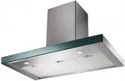
EN 4 4 CHARACTERISTICS Components Ref. Q.ty Product Components 1 1 Hood Body, complete with: Controls, Light, Blower, Filters 2 1 Telescopic Chimney comprising: 2.1 1 Upper Section 2.2 1 Lower Section 9 1 Reducer Flange ø 150-120 mm 10 1 Damper ø 150 14.1 2 Air Outlet Connection Extension 15 1 Air O...
Smeg Range Hoods Manuals
-
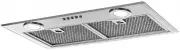
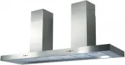
 Smeg 30403
User Manual
Smeg 30403
User Manual
-
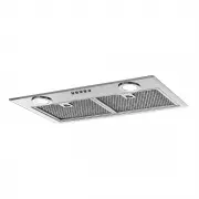
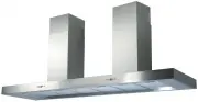
 Smeg CI2000SS
User Manual
Smeg CI2000SS
User Manual
-
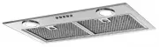
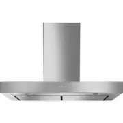
 Smeg CK2000LED
User Manual
Smeg CK2000LED
User Manual
-
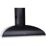
 Smeg CK2000SS
User Manual
Smeg CK2000SS
User Manual
-
 Smeg CLASSIC591SS
User Manual
Smeg CLASSIC591SS
User Manual
-
 Smeg CLASSIC592SS
User Manual
Smeg CLASSIC592SS
User Manual
-
 Smeg CLASSIC791SS
User Manual
Smeg CLASSIC791SS
User Manual
-
 Smeg CLASSIC792SS
User Manual
Smeg CLASSIC792SS
User Manual
-
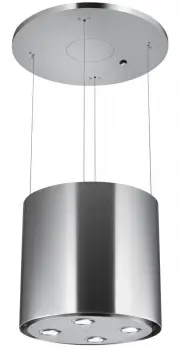
 Smeg CMVERTIGO
User Manual
Smeg CMVERTIGO
User Manual
-
 Smeg CMZOOM
User Manual
Smeg CMZOOM
User Manual
-
 Smeg IS7088D150SS
User Manual
Smeg IS7088D150SS
User Manual
-
 Smeg IS7088D180SS
User Manual
Smeg IS7088D180SS
User Manual
-
 Smeg IS7099X90
User Manual
Smeg IS7099X90
User Manual
-
 Smeg IS7599ENC-2
User Manual
Smeg IS7599ENC-2
User Manual
-
 Smeg K181X70
User Manual
Smeg K181X70
User Manual
-
 Smeg K7088D150SS
User Manual
Smeg K7088D150SS
User Manual
-
 Smeg K7088D180SS
User Manual
Smeg K7088D180SS
User Manual
-
 Smeg K90X
User Manual
Smeg K90X
User Manual
-
 Smeg KA1VA
User Manual
Smeg KA1VA
User Manual
-
 Smeg KA1VA2
User Manual
Smeg KA1VA2
User Manual