Fanimation CWRL4LA - User Manual
Fanimation CWRL4LA Remote Control – User Manual, read for free online in PDF format. We hope this helps you resolve any issues you may have. If you have further questions, please contact us through the contact form.

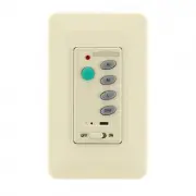
CWRL4 Wall Control
SPECIFICATION and INSTRUCTION SHEET
DESCRIPTION:
One Ceiling Fan & Light, 3 Speed Wall Control with Learn Receiver
ELECTRICAL SPECS:
FAN MODELS USED:
120 Volts, 60 Hertz, Fan 1.0 amp, Light Rating 190W (max.)
Incandescent or Halogen, 5 Wire Installation
May be used in conjunction with CRL4 Remote Control
See Catalog or visit our website
www.fanimation.com
for more information
NOTE: If fan or supply wires are different colors than indicated,
have this unit installed by a qualified electrician.
WARNING
To avoid possible electrical shock, be sure electricity is
turned off at the main fuse box before wiring.
NOTE: If you are not sure if the outlet box is grounded,
contact a licensed electrician for advise, as it must be
grounded for safe operation.
INSTALLING THE RECEIVER:
Ceiling fan must be set at HIGH speed and light kit (If any) at
1.
the ON position by pressing the “Light Switch” after installation.
Install Receiver in the Hanger Bracket:
2.
•
Slide remote Receiver into the Hanger Bracket (Figure 1).
• Connect wires as indicated: (Figure 2)
–Green Hanger Bracket and Hanger Ball wires to BARE (ground) wire.
–BLACK Receiver Unit wire (AC IN L) to BLACK supply wire.
–WHITE Receiver Unit wire (AC IN N). to WHITE supply wire.
–WHITE Receiver Unit wire (TO MOTOR N) to WHITE fan wire.
–BLACK Receiver Unit wire (TO MOTOR L) to BLACK fan wire.
–BLUE Receiver Unit wire (FOR LIGHT DOWN) to BLUE light wire.
•
Position all connected wires and receiver antenna to allow
installation of ceiling canopy.
•
Using canopy screws threaded into the hanger bracket reinstall
ceiling canopy.
IMPORTANT:
YOU MUST SET YOUR CEILING FAN TO HIGH SPEED AND LIGHT KIT
(IF ANY) TO THE ON POSITION BEFORE OPERATING YOUR REMOTE CONTROL.
Figure 2
Receiver Unit
Ceiling
Bracket
(Open End)
NOTE:
AC120V 60HZ
INPUT
WHITE (AC IN N)
AC SUPPLY
BLACK (AC IN L)
BLACK (AC IN L)
GREEN / YELLOW
CONTROL
WALL
BLACK (TO MOTOR L)
BLACK
BARE
GREEN
WHITE (TO MOTOR N)
BLACK (TO MOTOR L)
BLUE (FOR LIGHT)
BLUE
BLACK
WHITE
BLACK
BLACK (AC IN L)
GROUND WIRE
Figure 1
LEARN MODE PROCESS:
Control and receiver have been factory programmed. If replacing the
1.
transmitter or receiver, the learn mode process will need to be used.
After installing the unit and restoring power to your fan, press
2.
and hold the ”LEARNING BUTTON” 1~3seconds with a ball-point
pen or similar object. Make sure ON/OFF slide switch is in the
ON position. FAN will turn off and then turn to medium speed,
which indicates that the learning process has completed.
IMPORTANT: You must press the “LEARNING BUTTON”
within 60 seconds of restoring power to the fan. (Figure 4)
Please note, the wall control can learn multiple receivers.
4.
60 second time limit should eliminate need for this.
If light kit has CFL bulbs, please slide the “light dimmer function
3.
select switch” to “O” position. If installed incandescent light bulbs
onto ceiling fan, please slide the “light dimmer function select
switch” to “I” position.
10983 Bennett Parkway
Zionsville, IN 46077
(888) 567-2055 • FAX (866) 482-5215
Outside U.S. call (317) 733-4113
Visit Our Website @ www.fanimation.com
Copyright 2010 Fanimation
2010/02
WALL CONTROL FUNCTIONS:
WARNING
Check to see that all connections are tight, including ground,
and that no bare wire is visible at the wire connectors,
except for the ground wire. Do not operate fan until the
blades is in place. Noise and fan damage could result.
INSTALLING THE WALL CONTROL (Figure 3):
With power still off, remove existing wall plate, disconnect and
1.
remove the toggle switch from wall junction box. Save the 2
screws from the toggle switch.
Using the supplied wire connectors, make the electrical
2.
connections to the new wall control (transmitter) unit.
NOTE: Place control ON/OFF slide switch to the OFF position.
Carefully push all connected wires inside wall switch box.
3.
Secure wall control unit with 2 screws previously removed.
4.
Push and click the face plate onto the wall control (transmitter).
5.
Restore power
6.
Figure 3
Figure 4
ON/OFF- Press and release the light button
immediately to turn on or off the light.
Press and hold the light button to dim or
brighten light to the desired level and release
NOTE: feature cannot be used with CFL bulbs
Turns off the fan
Turns fan to high speed
Turns fan to medium speed
Turns fan to low speed
Turns off all power to your fan.
Learn mode button; Connects transmitter & receiver
ON/OFF for light dimmer function
H
M
L
OFF
OFF
ON
Receiver wires omitted for clarity.
Figure 3
Figure 2
I
O
L
OFF
ON
H
M
L
OFF
LIGHT
DIMMER
FUNCTION
SELECT
SWITCH
LEARNING
BUTTON
L
I
O
"Loading the manual" means you need to wait until the file loads and becomes available for online reading. Some manuals are very large, and the time they take to appear depends on your internet speed.