Fanimation C21 - User Manual
Fanimation C21 Remote Control – User Manual, read for free online in PDF format. We hope this helps you resolve any issues you may have. If you have further questions, please contact us through the contact form.

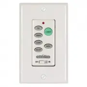
C21 Wall Control
SPECIFICATION and INSTRUCTION SHEET
How to Wire and Operate Your C21 Wall Control
NOTE:
If fan or supply wires are different colors than indicated,
have this unit installed by a quali
fi
ed electrician.
Check to see that all connections are tight, including
ground, and that no bare wire is visible at the wire
connectors, except for the ground wire. Do not operate
fan until the blades is in place. Noise and fan damage
could result.
WARNING
Figure 1b
Figure 1a
Wall Transmitter Unit Detail
(located on side of Wall Control)
Receiver Unit Detail
2. Wiring & Installing Wall Control Transmitter:
• With electrical power still disconnected, remove the
existing wall plate and switch.
• Make wiring connections with wire nuts as shown in
Figure 2.
– One black wire from wall control unit to black
(hot supply)
– One black wire from wall control unit to black wire
leading to ceiling outlet box.
– One green wire from wall control unit to wall outlet box.
• Attach wall control unit to outlet box using the two 6-32
screw provided.
• Attach wall plate to the switch control front using the two
small screws provided.
1. Setting the Code:
The remote unit has 16 different code
combinations. It may be necessary to test a couple frequency
code settings to improve signal reception and/or eliminate
interference from other remote control household items.
Multiple fans should have different code settings to allow
independent fan control. To set the code, perform these
steps.
• Transmitter:
located on back side of unit. Slide code
switches to your choice of up or down position. Factory setting
is all up. Do not use this position. With a small screwdriver or
ball point pen slide firmly up or down (Figure 1a).
• Receiver:
Slide code switches to the same positions as
set on your transmitter (Figure 1b).
To avoid possible electrical shock, be sure electricity is
turned off at the main fuse box before wiring.
NOTE: If you are not sure if the outlet box is grounded,
contact a licensed electrician for advice, as it must be
grounded for safe operation.
WARNING
DESCRIPTION:
One Ceiling Fan and Light, 3 Speed, Reversing Wall Control
FAN MODEL USED:
Must operate in conjunction with SW50 Switch Cap Control Receiver
May be used in conjunction with TR20** Remote Control
See Catalog or visit our website
www.fanimation.com
for more
information
Copyright 2010 Fanimation
2013/02
10983 Bennett Parkway
Zionsville, IN 46077
(888) 567-2055 • FAX (866) 482-5215
Outside U.S. call (317) 733-4113
Visit Our Website @ www.fanimation.com
BL-AC IN L
WH-AC IN N
BLK-TO MOTOR L
WH-TO MOTOR N
GRN or BARE GROUND
GRN from hanger ball
GRN from bracket
120
VAC SUPP
LY
(User Supplied)
GRN
GRN
BLK
BLK
FAN ASSEMBLY
Figure 2
3. Operating & Using Wall Transmitter:
• HI Push Button – high fan speed
• MED Push Button – medium fan speed
• LOW Push Button – low fan speed
• REV Push Button – toggles between air upflow and
air downflow
• OFF Push Button – fan off
• LIGHT Push Button –
toggles between light on or light off,
also works as light dimmer (see note
(if optional light kit or fitter is used)
*
NOTE:
To vary light intensity, hold down button to increase or
decrease brightness. Tap button quickly to turn light on or off.
The light button has auto resume, which maintains the same
brightness as the last time it was turned off.
"Loading the manual" means you need to wait until the file loads and becomes available for online reading. Some manuals are very large, and the time they take to appear depends on your internet speed.