Page 3 - ENGLISH; Contents; APPROVED FOR RESIDENTIAL APPLIANCES; PLEASE READ ENTIRE INSTRUCTIONS BEFORE PROCEEDING.; Save these Instructions for the Local Electrical Inspector’s use.
3 ENGLISH Contents Important safety notice................................................................................................................................................................................................. 4 Electrical & installation requirements ......................
Page 4 - IMPORTANT SAFETY NOTICE
4 I IMPORTANT SAFETY NOTICE I CAUTION FOR GENERAL VENTILATING USE ONLY. DO NOT USE TO EXHAUST HAZARDOUS OR EXPLOSIVE MATERIALS OR VAPOURS. I WARNING TO REDUCE THE RISK OF FIRE, ELECTRIC SHOCK, OR INJURY TO PERSONS, OBSERVE THE FOLLOWING: A. Use this unit only in the manner intended by the manufactur...
Page 5 - ELECTRICAL & INSTALLATION REQUIREMENTS; IMPORTANT; DIMENSIONS AND CLEARANCES; Models
5 ELECTRICAL & INSTALLATION REQUIREMENTS IMPORTANT Observe all governing codes and ordinances. It is the customer’s responsibility: • To contact a qualified electrical installer.• To assure that the electrical installation is adequate and in conformance with National Electrical Code, ANSI/NFPA 7...
Page 6 - LIST OF MATERIALS; CAUTION
6 LIST OF MATERIALS Removing the packaging. I CAUTION Remove carton carefully, Wear gloves to protect against sharp edges. I WARNING Remove the protective film covering the product before putting into operation. Supplied Part Pieces Supplied Part Pieces Hood assembly with blower and LED lamps alread...
Page 7 - Ducting options; Ducting version; Preparation; Installation; Ceiling support structures; Example A
7 Ducting options Closely follow the instructions set out in this manual. All responsability, for any eventual inconveniences, damages or fires caused by not complying with the instructions in this manual, is declined. Ducting version Ductless (Recirculating) The hood is equipped with a 6” (15.2 cm)...
Page 8 - Example B; Install Range Hood; Example C
8 Example B 2 x 4 cross framing Align duct to center of cooktop Hood front Cooktop outline NOTE: Top view ceiling joists parallel to front of hood 10 1 ⁄ 16 ” (25.5 cm) install cross- framing symmetrically over duct/cooktop Centerline Ø 6 1 ⁄ 4 ” (15.9 cm) duct 7 1 ⁄ 16 ” (17.9cm) 16” (40.6 cm) jois...
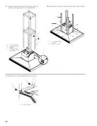
Page 10 - Install the 4 vertical supports with 16 - 4.2x8 mm screws.; Remove the 2 leveling screws from the structure.
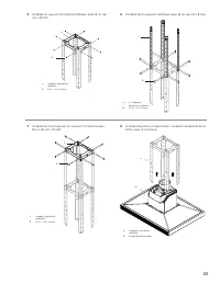
10 9 Attach the range hood assembly to the lower vertical supports with 2 leveling screws. A. 2 - Leveling screws B. Lower vertical support C. Place leveling screws through the structure A B C 10 Install the 4 vertical supports with 16 - 4.2x8 mm screws. Check everything is tightly screwed. A. 4 - L...
Page 11 - Electrical connection; WARNING; Complete the installation; ONLY FOR RECIRCULATING VERSION; Air deflector installation
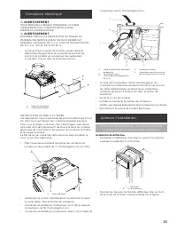
11 Electrical connection I WARNING TO REDUCE THE RISK OF FIRE, USE ONLY METAL DUCT WORK. ELECTRICAL SHOCK HAZARD. I WARNING TURN OFF POWER CIRCUIT AT THE SERVICE PANEL BEFORE WIRING THIS UNIT. 120 VAC, 15 OR 20 AMP CIRCUIT REQUIRED. • Facing the front of the range hood, remove the left knockout and ...
Page 12 - Duct cover installation (both ducted and non ducted versions)
12 A. Air deflector B. Assembly screws • Measure from the bottom of the air deflector to the bottom of the hood outlet, as shown. A A. Dimension to measure • Cut the duct at the measured size.• Slip the duct onto the bottom of the deflector.• Place the duct over the exhaust outlet from the hood.• Us...
Page 13 - • Take apart the stainless steel panel by removing its screws; • Secure the lower duct cover to the range hood canopy; Description of the hood
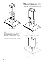
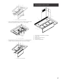
13 A. Lower duct covers B. 4 - Duct cover plastic bracket • Take apart the stainless steel panel by removing its screws as shown in drawing. A A A. 10 - stainless steel panel screws • Secure the lower duct cover to the range hood canopy using 4 - 4.2 x 8 mm screws. A A. 4 - 4.2x8 mm screws • Replace...
Page 14 - Control; CFM Reduction System
14 Control 1 2 3 4 5 6 1. Button ON/OFF motor (stand by) 2. Button for low speed (suction power) selection When flashing, it indicates that you must wash the grease filter. 3. Button for medium speed (suction power) selection 4. Button for high speed (suction power) selection 5. Button for intensive...
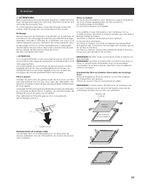
Page 15 - Maintenance; Cleaning; Grease Filter; Replacing a LED Lamp
15 Maintenance I ATTENTION! Before performing any maintenance operation, isolate the hood from the electrical supply by switching off at the connector and removing the connector fuse. Or if the appliance has been connected through a plug and socket, then the plug must be removed from the socket. Cle...
Page 16 - ELICA North America; TWO-YEAR LIMITED WARRANTY; TO OBTAIN SERVICE UNDER WARRANTY; Damage or failure to the product caused by operator abuse.; WHO IS COVERED; Register your product in; year of factory
16 ELICA North America TWO-YEAR LIMITED WARRANTY TO OBTAIN SERVICE UNDER WARRANTY Owner must present proof of original purchase date. Please keep a copy of your dated proof of purchase (sales slip) in order to obtain service under warranty. PARTS AND SERVICE WARRANTY For the period of two (2) years ...
Page 17 - FRANÇAIS; Table des matières; APPROUVÉ POUR LES APPAREILS DE TYPE RÉSIDENTIEL; VEUILLEZ LIRE CES INSTRUCTIONS AU COMPLET AVANT DE COMMENCER.; panneau avant de raccorder les fils de cet appareil.
17 FRANÇAIS Table des matières Avis de sécurité important ......................................................................................................................................................................................... 18 Exigences électriques et d’installation ................
Page 18 - AVIS DE SÉCURITÉ IMPORTANT
18 I AVIS DE SÉCURITÉ IMPORTANT I ATTENTION UTILISER CET APPAREIL À DES FINS DE VENTILATION GÉNÉRALE SEULEMENT. NE PAS UTILISER CET APPAREIL POUR ÉVACUER DES MATÉRIAUX OU DES VAPEURS DANGEREUX OU EXPLOSIFS. I AVERTISSEMENT POUR RÉDUIRE LES RISQUES D’INCENDIE, DE CHOC ÉLECTRIQUE ET DE BLESSURE, RESPE...
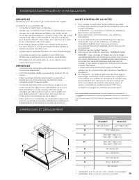
Page 19 - EXIGENCES ÉLECTRIQUES ET D’INSTALLATION; DIMENSIONS ET DÉGAGEMENT; Modèles
19 EXIGENCES ÉLECTRIQUES ET D’INSTALLATION IMPORTANT Respectez tous les codes et les ordonnances en vigueur. Le client a la responsabilité de : • Contacter un électricien-installateur.• Vérifier que l’installation électrique est adéquate et confor- me avec le Code national de l’électricité, ANSI/ NF...
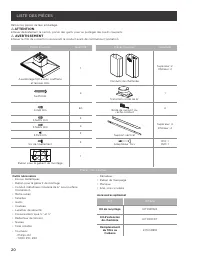
Page 20 - LISTE DES PIÈCES; ATTENTION
20 LISTE DES PIÈCES Retirer les pièces de leur emballage. I ATTENTION Enlever délicatement le carton, porter des gants pour se protéger des bords coupants. I AVERTISSEMENT Enlever le film de protection recouvrant le produit avant de commencer l’opération. Pièces Fournies Quantité Pièces Fournies Qua...
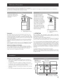
Page 21 - Méthodes d’évacuation; Version à conduit; Préparation; Structures de soutien au plafond; Exemple A
21 Méthodes d’évacuation Suivez à la lettre les directives présentées dans ce manuel. Le fabricant refuse toute responsabilité en ce qui a trait à tout préjudice, dommage ou incendie causé par la non observation des directives contenues dans le présent manuel. Version à conduit Version sans conduit ...
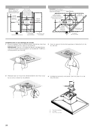
Page 22 - Exemple B; Installation des vis de montage de la hotte; Exemple C
22 Exemple B Cadre de croisement 2 x 4 Aligner el conduit au centre de la cuisinière Delimitation de la cuisinière 7 1 ⁄ 16 ” (17.9cm) REMARQUE: Vue du dessus - Solives du plafond parallèles à la faceavant de la hotte Face avant de la hotte Conduit Ø 6 1 ⁄ 4 ” (15.9cm) Espace entre les solives 16” (...
Page 25 - Connexion électrique; AVERTISSEMENT; Achever l’installation; POUR NON INDÉPENDANTE (recirculation) VERSION; Installation du déflecteur
25 Connexion électrique I AVERTISSEMENT POUR RÉDUIRE LE RISQUE D’INCENDIE, UTILISER UNIQUEMENT DES CONDUITS MÉTALLIQUES. RISQUE DU POIDS EXCESSIF. I AVERTISSEMENT ETEIGNEZ CIRCUIT D’ALIMENTATION AU NIVEAU DU PANNEAU DE SERVICE AVANT DE RACCORDER CET APPAREIL. EXIGENCE 120 V C.A., CIRCUIT DE DÉRIVATI...
Page 26 - REMARQUE
26 A A. Dimension à mesurer • Couper le conduit à la dimension mesurée.• Glisser le conduit dans le fond du déflecteur.• Placer le conduit assemblés sur la sortie d’évacuation de la hotte. • Utiliser de la toile isolante pour sceller le déflecteur et à l’extrémité de l’évacuation extérieure de la ho...
Page 27 - • Fixer la partie inférieure du cache-conduit à l’auvent de la; Description de la hotte
27 A A A. 10 vis - panneau en acier inoxydable • Fixer la partie inférieure du cache-conduit à l’auvent de la hotte de cuisinière en utilisant 4 vis - 4,2 x 8 mm A A. 4 vis - 4,2 x 8 mm • Remplacez le panneau en utilisant les vis précédemment retirées. Placez le panneau dans sa position d’origine. A...
Page 29 - Entretien
29 Entretien I ATTENTION! Before performing any maintenance operation, isolate the hood from the electrical supply by switching off at the connector and removing the connector fuse. Or if the appliance has been connected through a plug and socket, then the plug must be removed from the socket. Netto...
Page 30 - GARANTIE DE DEUX ANS; POUR OBTENIR UN DEPANNAGE SOUS GARANTIE; Dégât ou panne du produit causé par une mauvaise utilisation.; QUI EST COUVERT; Demandez le service après-vente; Enregistrez votre produit sur; et obtenez une; de
30 ELICA North America GARANTIE DE DEUX ANS POUR OBTENIR UN DEPANNAGE SOUS GARANTIE Le propriétaire doit présenter une preuve de la date d’achat. Garder une copie de votre preuve d’achat datée (ticket de caisse) de façon à pouvoir bénéficier du service après-vente sous garantie. GARANTIE PIECES DE R...
Page 31 - ESPAÑOL; Contenido; APROBADO PARA APARATOS DE USO DOMÉSTICO; ANTES DE CONTINUAR, LEA LAS INSTRUCCIONES POR COMPLETO.; Entregue al propietario estas instrucciones junto con la unidad.; Advertencia de seguridad:; de servicio y desbloquee el panel.
31 ESPAÑOL Contenido Aviso de seguridad importante.................................................................................................................................................................................. 32 Requisitos eléctricos y de instalación.................................
Page 32 - AVISO DE SEGURIDAD IMPORTANTE
32 I AVISO DE SEGURIDAD IMPORTANTE I PRECAUCIÓN SÓLO PARA USO DE VENTILACIÓN GENERAL. NO UTILIZAR PARA EXPULSAR VAPORES O MATERIALES PELIGROSOS O EXPLOSIVOS. I ADVERTENCIA PARA REDUCIR EL RIESGO DE FUEGO, DESCARGA ELÉCTRICA O LESIONES PERSONALES, RESPETE LO SIGUIENTE: A. Utilice esta unidad solament...
Page 34 - REQUISITOS ELÉCTRICOS Y DE INSTALACIÓN; IMPORTANTE; DIMENSIONES Y ESPACIOS LIBRES; Modelos
34 REQUISITOS ELÉCTRICOS Y DE INSTALACIÓN IMPORTANTE Cumpla todas las normativas y ordenanzas gubernamentales. Es responsabilidad del cliente: • Ponerse en contacto con un instalador eléctrico cualificado.• Asegurarse de que la instalación eléctrica es adecuada y en conformidad con National Electric...
Page 35 - LISTA DE MATERIALES; PRECAUCIÓN
35 LISTA DE MATERIALES Remoción de la confección I PRECAUCIÓN Quite la caja cuidadosamente, use guantes para protegerse contra los bordes afilados. I ADVERTENCIA Quite la película de protección que cubre el producto antes de ponerlo en funcionamiento. Piezas suministradas Piezas Piezas suministradas...
Page 36 - Tipos de ductos; Salida de escape; Preparación; Instalación; Estructuras de soporte al techo; Ejemplo A
36 Tipos de ductos Siga detenidamente las instrucciones expuestas en este manual. Se declina toda responsabilidad de cualquier inconveniencia, daños o incendios eventuales ocasionados por el incumplimiento de las instrucciones de este manual. Salida de escape Sin ducto de escape (recirculante) La ca...
Page 37 - Ejemplo B; Ejemplo C; Instalación de la campana
37 Ejemplo B 2 x 4 cruzado Alinear conducto al centro de la estufa Frente de la campana Contorno de la estufa NOTA: Las vigas del techo paralelas al frente de la estufa 10 1 ⁄ 16 ” (25.5 cm) instale un marco cruzado simétrico sobre la estufa Línea Central Conducto Ø 6 1 ⁄ 4 ” (15.9 cm) 7 1 ⁄ 16 ” (1...
Page 40 - Conexión eléctrica; ADVERTENCIA
40 Conexión eléctrica Características eléctricas (nominales) Modelos ESL636S3 ESL642S3 Voltaje 120 V~ Potencia 450 W Corriente 3.75 A Frecuencia 60 Hz Potencia Máx. de lámparas 4 x 2.5 W Consumo de energía Modo de espera 0.8 W/h Modo de operación 342.2 W/h 1 I ADVERTENCIA PARA REDUCIR EL RIESGO DE I...
Page 41 - Complete la instalación; SOLAMENTE PARA VERSIÓN RECIRCULANTE; Instalación del deflector; Instalación de las cubiertas del ducto (versión con y sin ducto
41 Complete la instalación SOLAMENTE PARA VERSIÓN RECIRCULANTE (Usando Kit Recirculante modelo KIT0141924) Instalación del deflector • Monte el deflector de aire con el soporte horizontal supe- rior con 2 tornillos de montaje provistos. A B A. Deflector B. Tornillos de montaje • Mida desde la parte ...
Page 42 - Descripción de la campana
42 A. Cubiertas inferiores del ducto B. 4 - Sujetadores de plástico de la cubierta del ducto • Retire el plato perimetral al remover sus tornilloa como se muestra en la imagen. A A A. 10 tornillos del plato perimetral • Asegure la cubierta inferior del ducto a la campana de cocina con escudete utili...
Page 44 - Mantenimiento
44 efectivamente el máximo rendimiento a <300 CFM. 3 Localice el sticker certificado de CFM dentro del empaque. 4 Adhiera el sticker en un área visible en el motor. Este sticker proveerá una certificación oficial a su inspec- tor local en el que se consta que el flujo máximo de aire ha sido reduc...
Page 45 - GARANTÍA LIMITADA DE DOS AÑOS; PARA OBTENER SERVICIO DENTRO DE GARANTÍA; Daños o fallas del producto causados por abuso del usuario.; QUIÉN ESTÁ CUBIERTO; Departamento de Servicio al Cliente; Registre su producto en; año de garantía de
45 ELICA North America GARANTÍA LIMITADA DE DOS AÑOS PARA OBTENER SERVICIO DENTRO DE GARANTÍA El propietario debe presentar su recibo original de la compra. Guarde por favor una copia de su recibo de compra como prue-ba, para recibir el servicio dentro del periodo de garantía. PARTES Y GARANTÍA DE S...
Page 46 - ELICA Latinoamérica; para reemplazar cualquier parte defectuosa.; QUÉ NO ESTÁ CUBIERTO
ELICA Latinoamérica GARANTÍA LIMITADA DE DOS AÑOS PARA OBTENER SERVICIO DENTRO DE GARANTÍA El propietario debe presentar su recibo original de la compra. Guarde por favor una copia de su recibo de compra como prue-ba, para recibir el servicio dentro del periodo de garantía. PARTES Y GARANTÍA DE SERV...