Page 2 - Instructions; General safety instructions
Instructions 4 1 Instructions 1.1 General safety instructions Risk of personal injury • During use the appliance and its accessible parts become very hot. Never touch the heating elements during use. • Protect your hands by wearing oven gloves when handling food inside the oven cavity. • Never try t...
Page 3 - Risk of damaging the appliance
Instructions 5 EN • If you need to move food or at the end of cooking, open the door 5 cm for a few seconds, let the steam come out, then open it fully. • Do not open the storage compartment (if present) when the oven is on and still hot. • The items inside the storage compartment could be very hot ...
Page 5 - Installation
Instructions 7 EN Installation • THIS APPLIANCE MUST NOT BE INSTALLED IN BOATS OR CARAVANS. • The appliance must not be installed on a stand. • Position the appliance into the cabinet cutout with the help of a second person. • To prevent overheating, the appliance must not be installed behind a deco...
Page 6 - Manufacturer liability
Instructions 8 1.3 Manufacturer liability The manufacturer declines all liability for damage to persons or property caused by:• use of the appliance other than the one envisaged; • non-observance of the user manual provisions; • tampering with any part of the appliance; • use of non-original spare p...
Page 7 - How to read the user manual
Instructions 9 EN 1.7 How to read the user manual This user manual uses the following reading conventions: 1. Sequence of instructions for use.• Standalone instruction. Instructions General information on this user manual, on safety and final disposal. Description Description of the appliance and it...
Page 8 - Description; General Description
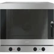
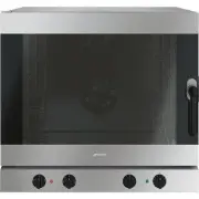
Description 10 2 Description 2.1 General Description 1 Backguard 2 Cooking hob 3 Control panel 4 Oven light 5 Seal 6 Door 7 Fan 8 Storage compartment Rack/tray support frame shelf
Page 9 - Function knob
Description 11 EN 2.2 Cooking hob AUX = AuxiliarySR = Semi-rapid R = RapidDUAL = Ultra rapid 2.3 Control panel 1 Function knob The oven's various functions are suitable for different cooking modes. After selecting the required function, set the cooking temperature using the temperature knob. 2 Tempe...
Page 10 - Available accessories
Description 12 4 Hob burner knobs Useful for lighting and adjusting the hob burners.Press and turn the knobs anti-clockwise to the value to light the relative burners. Turn the knobs to the zone between the maximum and minimum setting to adjust the flame. Return the knobs to the position to turn off...
Page 11 - Tray rack
Description 13 EN Tray rack To be placed over the top of the oven tray; for cooking foods which may drip. Deep tray Useful for collecting fat from foods placed on the rack above. Rotisserie rod Useful for cooking chicken and all foods which require uniform cooking over their entire surface. Reductio...
Page 12 - Use; Danger of burns
Use 14 3 Use 3.1 Instructions High temperature inside the oven during use Danger of burns • Keep the oven door closed during cooking. • Protect your hands wearing heat resistant gloves when moving food inside the oven. • Do not touch the heating elements inside the oven. • Do not pour water directly...
Page 13 - Escaping gas may cause an explosion.
Use 15 EN Escaping gas may cause an explosion. If you smell gas or notice any faults in the gas installation:• Immediately shut off the gas supply or close the gas cylinder valve. • Immediately extinguish all naked flames and cigarettes. • Do not use any light or appliance switches and do not pull a...
Page 14 - Using the accessories; Reduction pan stands
Use 16 3.3 Using the accessories Reduction pan stands The reduction pan stands have to be placed on the hob grids. Make sure they are properly placed. Tray rack The tray rack has to be inserted into the tray. In this way fat can be collected separately from the food which is being cooked. Racks and ...
Page 15 - Rotisserie rod
Use 17 EN Rotisserie rod 1. Insert the 4 supplied bushings in the 4 corner holes of the deep tray and screw them onto the ring nuts with a suitable tool (such as a screwdriver). 2. Position the rotisserie supports in the bushings as shown in the figure below. 3. Prepare the rotisserie rod with the f...
Page 16 - Using the storage compartment
Use 18 6. Insert the tip of the rod in the rotisserie motor housing on the left of the rear wall of the oven. 7. To activate the rotisserie, turn the function knob to the position and set the cooking temperature using the temperature knob. 8. When cooking is complete, remove the tray with the rotiss...
Page 17 - Using the cooktop; Practical tips for using the hob
Use 19 EN 3.5 Using the cooktop All the appliance's control and monitoring devices are located together on the front panel. The burner controlled by each knob is shown next to the knob. The appliance is equipped with an electronic ignition device. Simply press the knob and turn it anti-clockwise to ...
Page 18 - Switching on the oven
Use 20 3.6 Using the oven Switching on the oven To switch on the oven:1. Select the cooking function using the function knob. 2. Select the temperature using the temperature knob. Functions list Ensure that the programmer clock shows the cooking duration symbol , otherwise it will not be possible to...
Page 19 - Fan assisted; and
Use 21 EN Fan assisted The operation of the fan, combined with traditional cooking, ensures consistent cooking even with complex recipes. Perfect for biscuits and cakes, even when simultaneously cooked on several levels. (For multiple-level cooking, we recommend using the 2 nd and 4 th shelf). Fan f...
Page 20 - General advice
Use 22 3.7 Cooking advice General advice • Use a fan assisted function to achieve consistent cooking at several levels. • It is not possible to shorten cooking times by increasing the temperature (the food could be overcooked on the outside and undercooked on the inside). Advice for cooking meat • C...
Page 21 - To save energy
Use 23 EN To save energy • Stop cooking a few minutes before the time normally used. Cooking will continue for the remaining minutes with the heat which has accumulated inside the oven. • Reduce any opening of the door to a minimum to avoid heat dispersal. • Keep the inside of the appliance clean at...
Page 22 - Timed cooking
Use 24 Timed cooking 1. After selecting a cooking function and temperature, press the key . The display will show the digits and the symbol displayed between the hours and the minutes. 2. Use the key or to set the required minutes. 3. Wait approx. 5 seconds without pressing any key in order for the ...
Page 23 - Minute minder timer
Use 25 EN 5. At the end of cooking the heating elements will be deactivated. On the display, the symbol turns off, the symbol flashes and the buzzer sounds. 6. To turn off the buzzer just press any key of the programmer clock. 7. Press the keys and at the same time to reset the programmer clock. Min...
Page 24 - Cooking information table
Use 26 Cooking information table Food Weight (Kg) Function Shelf Temperature (°C) Time (minutes) Lasagne 3 - 4 Convection 1 220 - 230 45 - 50 Pasta bake 3 - 4 Convection 1 220 - 230 45 - 50 Roast veal 2 Fan assisted/Fan forced 2 180 - 190 90 - 100 Pork 2 Fan assisted/Fan forced 2 180 - 190 70 - 80 S...
Page 25 - Cleaning and maintenance; Cleaning the appliance; Recommendations for cleaning the hob
Cleaning and maintenance 27 EN 4 Cleaning and maintenance 4.1 Instructions 4.2 Cleaning the appliance Recommendations for cleaning the hob To keep the surfaces in good condition, they should be cleaned regularly after use. Let them cool first. Cleaning the hob 1. Pour some non-abrasive detergent on ...
Page 26 - Cleaning the igniters and thermocouples
Cleaning and maintenance 28 Cleaning the igniters and thermocouples • If necessary, clean the igniters and thermocouples with a damp cloth. • If there is any dry residue, remove it with a toothpick or needle. Cleaning the oven cavity In order to keep your oven in the best possible condition, clean i...
Page 27 - Cleaning the top section
Cleaning and maintenance 29 EN Cleaning the top section The oven cavity is fitted with a tilting heating element which facilitates cleaning the top part (roof) of the oven.1. Free the upper heating element by gently lifting it and rotating its retainers by 90 degrees. 2. Gently lower the heating ele...
Page 28 - Vapour Clean setting
Cleaning and maintenance 30 • Pour approximately 40 cc of water into the tray. Make sure it does not overflow out of the cavity. • Spray a water and washing up liquid solution inside the oven using a spray nozzle. Direct the spray against the side walls, upwards, downwards and towards the deflector....
Page 29 - Removing the door; Grasp the door on both sides with both; Cleaning the door glazing
Cleaning and maintenance 31 EN 4.4 Removing the door For easier cleaning it is recommended to remove the door and place it on a tea towel.To remove the door proceed as follows:1. Open the door completely and insert two pins into the holes on the hinges indicated in the figure. 2. Grasp the door on b...
Page 30 - Removing the internal glass panes
Cleaning and maintenance 32 Removing the internal glass panes For easier cleaning the internal glass panes of the door can be removed.1. Open the door.2. Place the pins into the holes to prevent accidental closing of the door. 3. Pull the rear part of the internal glass pane gently upwards, followin...
Page 31 - Extraordinary maintenance; Replacing the oven light bulb
Cleaning and maintenance 33 EN 4.6 Extraordinary maintenance Replacing the oven light bulb 1. Completely remove all accessories from inside the oven. 2. Remove the racks/trays support frames. 3. Remove the bulb cover using a tool (e.g. a screwdriver). 4. Slide out and remove the light bulb. 5. Fit t...
Page 32 - Removing and installing the oven seal
Cleaning and maintenance 34 Removing and installing the oven seal To remove the oven seal:• Unhook the clips in the 4 corners and in the centre, then pull the oven seal. To install the oven seal:• Hook the clips in the 4 corners and in the centre onto the oven seal. Oven seal maintenance tips The se...
Page 33 - Installation; Clearances above and around domestic appliances; Requirements
Installation 35 EN 5 Installation 5.1 Clearances above and around domestic appliances This appliance must be installed by an authorised person in accordance with this instruction manual, AS/NZS 5601.1 – Gas installations (installation and pipe sizing), local gas fitting regulations, local electrical...
Page 34 - Additional requirements for
Installation 36 3. Additional requirements for Freestanding and Elevated Cooking Appliaces – (Measurements D & E) Where D, the distance from the periphery of the nearest burner to a horizontal combustible surface is less than 200 mm, then E shall be 10 mm or more, or the horizontal surface shall...
Page 35 - The regulator supplied must be fitted; Gas Approval onsulting Pty Ltd.
Installation 37 EN Connection of the appliance to the gas supply must be in accordance with the requirements of AS5601. A ½” BSP connector at the inlet is recommended and the gas supply line to the appliance must be of adequate length to allow sufficient withdrawal of appliance for service or discon...
Page 36 - Connection to liquid gas
Installation 38 4. If the pressure is 2.75kPa, reassemble the burner and perform the final checks as per this instruction manual. 5. If the pressure is not 2.75kPa, disconnect the appliance and check/adjust/replace the LPG cylinder regulator(s) as appropriate in accordance with AS/NZS5601. Connectio...
Page 37 - Adaptation to different types of; Replacing nozzles
Installation 39 EN 5.3 Adaptation to different types of gas In case of operation with other types of gas, the burner nozzles must be changed and the minimum flame adjusted on the gas taps. Replacing nozzles 1. Remove the pan stands, burner caps and flame-spreader crowns to access the burner casings....
Page 38 - Burner and nozzle characteristics table; Heavy appliance
Installation 40 Burner and nozzle characteristics table Appliance dimensions (mm) Location of gas and electrical connection points. 5.4 Positioning NG 1.0 kPA AUX SR R DUAL (int + ext) Nominal gas consumption (MJ/h) 3.9 7.5 12 18.0 Injector (1/100 mm) 90 120 155 90 + 175 ULPG 2.75 kPa AUX SR R DUAL ...
Page 39 - Overall dimensions
Installation 41 EN Overall dimensions 1 Minimum distance from the sides walls or other flammable materials. 2 Minimum cabinet width ( =A ). General information This appliance may be installed next to walls, one of which must be higher than the worktop, at a minimum distance of 50 mm from the side of...
Page 40 - Positioning and levelling
Installation 42 B - Class 2 subclass 1 (Built-in appliance) C - Class 2 subclass 1 (Built-in appliance) Positioning and levelling Properly level the appliance on the floor to ensure better stability.• After making the electrical and/or gas connections, screw or unscrew the bottom part of the foot un...
Page 41 - Assembling the skirt
Installation 43 EN Assembling the skirt The backguard must always be positioned and secured correctly on the appliance.1. Loosen the 6 screws on the back of the top ( A ) and unscrew the 2 screws ( B ) on the side part of the backguard. 2. Place the backguard on the top. Align the 6 bottom slots of ...
Page 42 - Wall fixing
Installation 44 Wall fixing 1. Turn the screw placed behind the cooktop near the gas connection. 2. Attach the chain to the cooker with the screw just removed. 3. Stretch it out horizontally so that the other end of the chain touches the wall. 4. Mark the wall in the position where the hole is to be...
Page 43 - Electrical connection; General information
Installation 45 EN 5.5 Electrical connection General information Check the grid characteristics against the data indicated on the plate.The identification plate bearing the technical data, serial number and brand name is visibly positioned on the appliance.Do not remove this plate for any reason.Per...
Page 44 - For the installer
Installation 46 5.6 For the installer • The plug must remain accessible after the installation is complete. Do not kink or trap the mains connection cable. • The appliance must be fitted according to the installation diagrams. • Do not attempt to turn or stress the threaded elbow on the manifold. Yo...


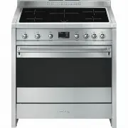
 Smeg A11X-7
User Manual
Smeg A11X-7
User Manual
 Smeg A11XPY-9
User Manual
Smeg A11XPY-9
User Manual
 Smeg A1PYID-7
User Manual
Smeg A1PYID-7
User Manual
 Smeg A1PYID-9
User Manual
Smeg A1PYID-9
User Manual
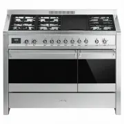 Smeg A3AU-81
User Manual
Smeg A3AU-81
User Manual
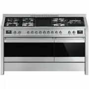 Smeg A5AU-81
User Manual
Smeg A5AU-81
User Manual
 Smeg ALFA1035EH
User Manual
Smeg ALFA1035EH
User Manual
 Smeg ALFA1035EHDS
User Manual
Smeg ALFA1035EHDS
User Manual
 Smeg ALFA1035EHT
User Manual
Smeg ALFA1035EHT
User Manual
 Smeg ALFA1035H
User Manual
Smeg ALFA1035H
User Manual
 Smeg ALFA1035H-2
User Manual
Smeg ALFA1035H-2
User Manual
 Smeg ALFA420EH
User Manual
Smeg ALFA420EH
User Manual
 Smeg ALFA420EHDS
User Manual
Smeg ALFA420EHDS
User Manual
 Smeg ALFA420EHT
User Manual
Smeg ALFA420EHT
User Manual
 Smeg ALFA625EH
User Manual
Smeg ALFA625EH
User Manual
 Smeg ALFA625EHDS
User Manual
Smeg ALFA625EHDS
User Manual
 Smeg ALFA625EHT
User Manual
Smeg ALFA625EHT
User Manual
 Smeg ALFA625H
User Manual
Smeg ALFA625H
User Manual
 Smeg ALFA625H-2
User Manual
Smeg ALFA625H-2
User Manual
 Smeg ALFA625HR-2
User Manual
Smeg ALFA625HR-2
User Manual