Page 2 - Instructions; General safety instructions
Instructions 4 1 Instructions 1.1 General safety instructions Risk of personal injury • During use the appliance becomes hot. Care should be taken to avoid touching heating elements inside the oven. • Protect your hands by wearing oven gloves when handling food inside the oven cavity. • Never try to...
Page 4 - Risk of damaging the appliance
Instructions 6 • If the power supply cable is damaged, contact technical support immediately and they will replace it. Risk of damaging the appliance • Do not use abrasive or corrosive detergents (e.g. scouring powders, stain removers and metallic sponges) on glass parts. • Use wooden or plastic ute...
Page 5 - Installation
Instructions 7 EN • If any liquid does boil over or spill, remove the excess from the cooktop. • Take care not to spill acidic substances such as lemon juice or vinegar onto the cooktop. • Do not put empty pans or frying pans on switched on cooking zones. • Do not use steam jets to clean the applian...
Page 6 - For this appliance
Instructions 8 check that the tightening torque of gas connections is between 10 Nm and 15 Nm. • At the end of the installation, check for any leaks with a soapy solution, never with a flame. • Have the electrical connection performed by authorised persons. • The appliance must be connected to earth...
Page 7 - • Place the supplied data plate to a; How to read the user manual
Instructions 9 EN • Place the supplied data plate to a suitable adjacent surface or within the instruction manual for future reference. 1.3 Manufacturer liability The manufacturer declines all liability for damage to persons or property caused by:• use of the appliance other than the one envisaged; ...
Page 9 - Description; General Description
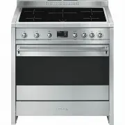
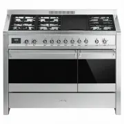
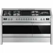
Description 11 EN 2 Description 2.1 General Description 1 Backguard 2 Cooktop 3 Control panel 4 Oven light 5 Seal 6 Door 7 Fan 8 Storage compartment Rack/tray support frame shelf
Page 10 - AUX
Description 12 2.2 Cooktop AUX = Auxiliary burner SR = Semi-rapid burner R = Rapid burner UR = Ultra rapid burner 2.3 Control panel 1 Temperature knob This knob allows you to select the cooking temperature. Turn the knob clockwise to the required value, between the minimum and maximum setting. 2 Ind...
Page 11 - Available accessories
Description 13 EN 5 Function knob The oven's various functions are suitable for different cooking modes. After selecting the required function, set the cooking temperature using the temperature knob. 6 Cooktop burner knobs Useful for lighting and adjusting the cooktop burners. Press and turn the kno...
Page 12 - Rack
Description 14 Rack Useful for supporting containers with food during cooking. Tray rack To be placed over the top of the oven tray; for cooking foods which may drip. Tray Useful for collecting fat from foods placed on the rack above. Deep tray Useful for collecting fat from foods placed on the rack...
Page 13 - Use; Danger of burns
Use 15 EN 3 Use Instructions High temperature inside the oven during use Danger of burns • Keep the oven door closed during cooking. • Protect your hands wearing heat resistant gloves when moving food inside the oven. • Do not touch the heating elements inside the oven. • Do not pour water directly ...
Page 14 - Escaping gas may cause an explosion.
Use 16 Escaping gas may cause an explosion. If you smell gas or notice any faults in the gas installation:• Immediately shut off the gas supply or close the gas cylinder valve. • Immediately extinguish all naked flames and cigarettes. • Do not use any light or appliance switches and do not pull any ...
Page 15 - Using the accessories; Racks and trays
Use 17 EN 3.2 Using the accessories Racks and trays Racks and trays have to be inserted into the side guides until they come to a complete stop.• The mechanical safety locks that prevent the rack from being taken out accidentally have to face downwards and towards the oven back. Ring reducers The ri...
Page 16 - Using the cooktop; Practical tips for using the cooktop
Use 18 3.3 Using the cooktop All the appliance's control and monitoring devices are located together on the front panel. The burner controlled by each knob is shown next to the knob. The appliance is equipped with an electronic ignition device. Simply press the knob and turn it anti-clockwise to the...
Page 17 - Using the storage compartment; Switching on the oven
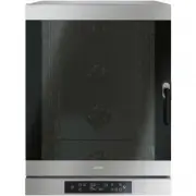
Use 19 EN 3.4 Using the storage compartment The storage compartment is at the bottom of the cooker. To open it, pull the handle towards you. It can be used to store cookware or metallic objects necessary when using the appliance. 3.5 Using the oven Switching on the oven To switch on the oven:1. Sele...
Page 18 - and
Use 20 Grill The heat coming from the grill element gives perfect grilling results above all for thin and medium thickness meat and, in combination with the rotisserie (where fitted), gives the food an even browning at the end of cooking. Perfect for sausages, spare ribs and bacon. This function ena...
Page 19 - General advice
Use 21 EN 3.6 Cooking advice General advice • Use a fan assisted function to achieve consistent cooking at several levels. • It is not possible to shorten cooking times by increasing the temperature (the food could be overcooked on the outside and undercooked on the inside). Advice for cooking meat ...
Page 20 - Advice for defrosting and proving
Use 22 Advice for defrosting and proving • Place frozen foods without their packaging in a lidless container on the first shelf of the oven. • Avoid overlapping the food.• To defrost meat, use the rack placed on the second level and a tray on the first level. In this way, the liquid from the defrost...
Page 21 - Timed cooking
Use 23 EN Timed cooking 1. Keep the clock key pressed until the symbol appears. 2. Press the clock key again. On the display the symbol and the text appear, alternating with the current time. 3. Use the value increase and value decrease keys to set the required minutes of cooking. 4. Select a functi...
Page 23 - Minute minder timer
Use 25 EN Minute minder timer The minute minder timer can be activated at any time. 1. Keep the clock key pressed for per a few seconds. The display shows the figures and the symbol flashing between the hours and minutes. 2. Use the value increase and value decrease keys to set the number of minutes...
Page 24 - Cooking information table
Use 26 Cooking information table Food Weight (Kg) Function Runner position from the bottom Temperature (°C) Time (minutes) Lasagne 3 - 4 Convection 1 220 - 230 45 - 50 Pasta bake 3 - 4 Convection 1 220 - 230 45 - 50 Roast veal 2 Fan assisted/Fan forced 2 180 - 190 90 - 100 Pork 2 Fan assisted/Fan fo...
Page 25 - Cleaning and maintenance; Cleaning the appliance; Cleaning the cooktop
Cleaning and maintenance 27 EN 4 Cleaning and maintenance Instructions 4.1 Cleaning the appliance Recommendations for cleaning the cooktop To keep the surfaces in good condition, they should be cleaned regularly after use. Let them cool first. Cleaning the cooktop 1. Pour some non-abrasive detergent...
Page 26 - Cleaning the igniters and thermocouples; Removing the door; Grasp the door on both sides with both
Cleaning and maintenance 28 Cleaning the igniters and thermocouples • If necessary, clean the igniters and thermocouples with a damp cloth. • If there is any dry residue, remove it with a toothpick or needle. Recommendations for cleaning the oven cavity For the best oven upkeep, clean it regularly a...
Page 27 - To reassemble the door, put the hinges in; Cleaning the door glazing; Remove the intermediate glass panes by
Cleaning and maintenance 29 EN 3. To reassemble the door, put the hinges in the relevant slots in the oven, making sure that grooved sections A are resting completely in the slots. Lower the door and once it is in place remove the pins from the holes in the hinges. 4.3 Cleaning the door glazing The ...
Page 28 - Removing racks/trays support frames
Cleaning and maintenance 30 4. Clean the external glass pane and the panes previously removed. Use absorbent kitchen roll. In case of stubborn dirt, wash with a damp sponge and neutral detergent. 5. Refit the panes in the reverse order in which they were removed. 6. Reposition the internal glass pan...
Page 29 - Door lock lever activated; Move the door lock lever to the right until
Cleaning and maintenance 31 EN Manually disengaging the door lock lever The door lock lever is located in the first slot on the left under the control panel, in the upper part of the front of the oven. During normal cleaning operations, the door lock lever may be activated accidentally. Door lock le...
Page 30 - Preliminary operations
Cleaning and maintenance 32 4.5 Pyrolytic cycle Preliminary operations Before starting the pyrolytic cycle:• Clean the internal glass pane following the usual cleaning instructions. • For very stubborn encrustations spray an oven cleaning product onto the glass (read the warnings on the product); le...
Page 31 - Setting of programmed pyrolytic cycle
Cleaning and maintenance 33 EN 6. At the end of the pyrolytic cycle, all the numbers will flash and a buzzer will sound to indicate the end of the automatic cleaning cycle. 7. Return the function knob to the " 0 " position. 8. The door remains locked as long as the temperature inside the ove...
Page 32 - Extraordinary maintenance; Replacing the oven light bulb
Cleaning and maintenance 34 4.6 Extraordinary maintenance Replacing the oven light bulb 1. Completely remove all accessories from inside the oven. 2. Remove the racks/trays support frames. 3. Remove the bulb cover using a tool (e.g. a screwdriver). 4. Slide out and remove the light bulb. 5. Fit the ...
Page 33 - The appliance does not work.
Cleaning and maintenance 35 EN What to do if... The appliance does not work. • The circuit breaker is faulty: look in the fuse box and check that the circuit breaker is in working order. • Power cut: check whether the kitchen light works. The gas burner does not ignite. • Power cut or damp ignition ...
Page 34 - Installation; Minimum clearance to; Freestanding cooker
Installation 36 5 Installation 5.1 Minimum clearance to combustible surfaces Freestanding cooker A 600 mm (Overhead) measured from the highest part of the highest burner and 750 mm for an exhaust fan. B 200 mm (Vertical combustible surface) measured form the edge of the nearest burner. C 10 mm (Hori...
Page 35 - Natural Gas
Installation 37 EN This appliance is suitable for connection with rigid pipe or flexible hose. The isolating manual shut-off valve connection point must be accessible when the appliance is installed.Flexible hose assembly must be certified to AS/NZS 1869 class B or D, be of appropriate internal diam...
Page 36 - Room ventilation
Installation 38 Room ventilation The room containing the appliance should have a permanent air supply in accordance with the standards in force. The room where the appliance is installed must have enough air flow needed for the regular combustion of gas and the necessary air change in the room itsel...
Page 37 - Adaptation to different types of; Replacing nozzles
Installation 39 EN 5.3 Adaptation to different types of gas In case of operation with other types of gas, the burner nozzles must be changed and the minimum flame adjusted on the gas cocks. Replacing nozzles 1. Remove the pan stands, burner caps and flame-spreader crowns to access the burner casings...
Page 38 - Burner and nozzle characteristics table; Heavy appliance
Installation 40 Burner and nozzle characteristics table Overall dimensions Location of gas and electrical connection points. E Gas connection G Electrical connection 5.4 Positioning 1 ULPG 2.75 kPa AUX SR R UR Nominal gas consumption (MJ/h) 4.0 7.0 11.0 15.0 Injector (1/100 mm) 54 68 88 105 2 NG 1.0...
Page 39 - General information
Installation 41 EN General information This appliance may be installed next to walls, one of which must be higher than the worktop, at a minimum distance of 50 mm from the side of the appliance, as shown in figures A and C relative to the installation classes.Any wall units positioned above the work...
Page 40 - Positioning and levelling
Installation 42 Positioning and levelling • After making the gas and electrical connections, screw on the four feet supplied with the appliance. The appliance must sit level on the floor to ensure stability.• Screw or unscrew the bottom part of the foot until the appliance is stable and level on the...
Page 41 - Align the base of the hook on the
Installation 43 EN 3. Assemble the fastening bracket. 4. Align the base of the hook on the fastening bracket with the base of the slot on the wall fastening plate. 5. Align the base of the fastening bracket with the ground and tighten the screws to fix the measurements. 6. Use 50 mm for the distance...
Page 42 - Wall fixing
Installation 44 7. Move the bracket onto the wall and mark the position of the holes to be drilled in the wall. 8. After drilling the holes in the wall, use wall plugs and screws to fasten the bracket to the wall. 9. Push the cooker towards the wall, and at the same time, insert the bracket in the p...
Page 43 - Mark the wall in the position where the
Installation 45 EN 4. Mark the wall in the position where the hole is to be drilled. 5. Drill the hole and insert a wall plug. 6. Attach the chain and push the appliance to the wall. Assembling the upstand The upstand must always be positioned and secured correctly on the appliance.1. Loosen the two...
Page 44 - Assembling the toe skirt
Installation 46 3. Clip the tongues of the upstand to the ventilation slot of the cooktop. ( A ) 4. Secure the upstand to the cooktop by tightening the 2 screws previously loosened. Assembling the toe skirt The toe skirt must always be positioned and secured correctly on the appliance.1. Use a screw...
Page 45 - Electrical connection
Installation 47 EN 5.5 Electrical connection General information Check the grid characteristics against the data indicated on the plate.The identification plate bearing the technical data, serial number and brand name is visibly positioned on the appliance.Do not remove this plate for any reason.Per...
Page 46 - Access to the terminal board; Access via the plate
Installation 48 5.6 Access to the terminal board Access via the plate To connect the power supply cable, access to the terminal board on the rear cover:1. Remove the screws securing the lid to the rear cover. 2. Slightly turn the lid and remove it from its housing. 3. Install the power supply cable....
Page 47 - Access via the rear casing; For the installer
Installation 49 EN Access via the rear casing To connect the power cable, remove the fastening screws on the rear casing as shown in the figure. Fixed connection Fit the power line with an all-pole circuit breaker with a contact separation distance sufficient to provide complete disconnection in cat...


 Smeg A11X-7
User Manual
Smeg A11X-7
User Manual
 Smeg A11XPY-9
User Manual
Smeg A11XPY-9
User Manual
 Smeg A1PYID-7
User Manual
Smeg A1PYID-7
User Manual
 Smeg A1PYID-9
User Manual
Smeg A1PYID-9
User Manual
 Smeg A3AU-81
User Manual
Smeg A3AU-81
User Manual
 Smeg A5AU-81
User Manual
Smeg A5AU-81
User Manual
 Smeg ALFA1035EH
User Manual
Smeg ALFA1035EH
User Manual
 Smeg ALFA1035EHDS
User Manual
Smeg ALFA1035EHDS
User Manual
 Smeg ALFA1035EHT
User Manual
Smeg ALFA1035EHT
User Manual
 Smeg ALFA1035H
User Manual
Smeg ALFA1035H
User Manual
 Smeg ALFA1035H-2
User Manual
Smeg ALFA1035H-2
User Manual
 Smeg ALFA420EH
User Manual
Smeg ALFA420EH
User Manual
 Smeg ALFA420EHDS
User Manual
Smeg ALFA420EHDS
User Manual
 Smeg ALFA420EHT
User Manual
Smeg ALFA420EHT
User Manual
 Smeg ALFA625EH
User Manual
Smeg ALFA625EH
User Manual
 Smeg ALFA625EHDS
User Manual
Smeg ALFA625EHDS
User Manual
 Smeg ALFA625EHT
User Manual
Smeg ALFA625EHT
User Manual
 Smeg ALFA625H
User Manual
Smeg ALFA625H
User Manual
 Smeg ALFA625H-2
User Manual
Smeg ALFA625H-2
User Manual
 Smeg ALFA625HR-2
User Manual
Smeg ALFA625HR-2
User Manual