Page 2 - Instructions; General safety instructions
Instructions 4 1 Instructions 1.1 General safety instructions Risk of personal injury • WARNING - Accessible parts will become hot when in use. To avoid burns young children should be kept away. • Protect your hands by wearing oven gloves when handling food inside the oven cavity. • Never try to put...
Page 3 - Risk of damaging the appliance
Instructions 5 EN cooking. • If you need to move food or at the end of cooking, open the door 5 cm for a few seconds, let the steam come out, then open it fully. • Do not open the storage compartment (if present) when the oven is on and still hot. • The items inside the storage compartment could be ...
Page 5 - Installation
Instructions 7 EN pan stands, flame-spreader crowns and burner caps in a dishwasher. • Never use the oven door to lever the appliance into place when fitting. • Avoid exerting too much pressure on the oven door when open. • Do not use the handle to lift or move the appliance. Installation • THIS APP...
Page 6 - For this appliance
Instructions 8 For this appliance • WARNING: Ensure the appliance is switched off before replacing the lamp to avoid the possibility of electric shock. • Do not rest any weight or sit on the open door of the appliance. • Take care that no objects are stuck in the doors. 1.2 Identification plate • Th...
Page 7 - How to read the user manual
Instructions 9 EN 1.6 How to read the user manual This user manual uses the following reading conventions: 1. Sequence of instructions for use.• Standalone instruction. Instructions General information on this user manual, on safety and final disposal. Description Description of the appliance and it...
Page 8 - Description; General Description
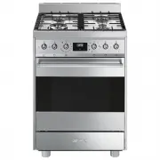
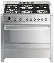
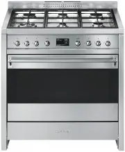
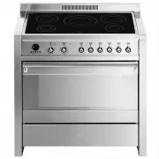
Description 10 2 Description 2.1 General Description 60cm models 1 Backguard 2 Cooktop 3 Control panel 4 Oven light 5 Seal 6 Door 7 Fan 8 Storage compartment Rack/tray support frame shelf 70cm models
Page 9 - AUX
Description 11 EN 2.2 Cooktop 60cm models 70cm models AUX = Auxiliary SR = Semi-rapid R = Rapid UR2 = Ultra rapid
Page 10 - Cooktop burner knobs
Description 12 2.3 Control panel 60cm models 70cm models 1 Cooktop burner knobs Useful for lighting and adjusting the cooktop burners. Press and turn the knobs anti-clockwise to the value to light the relative burners. Turn the knobs to the zone between the maximum and minimum setting to adjust the ...
Page 11 - Available accessories; Useful when using a wok.
Description 13 EN 2.4 Other parts Shelves The appliance features shelves for positioning trays and racks at different heights. The insertion heights are indicated from the bottom upwards (see 2.1 General Description). Cooling fan The fan cools the oven and comes into operation during cooking.The fan...
Page 12 - Deep tray
Description 14 Deep tray Useful for collecting fat from foods placed on the rack above. Tray rack Useful for supporting containers with food during cooking. Rack Useful for supporting containers with food during cooking. The accessories intended to come into contact with food are made of materials t...
Page 13 - Use; Danger of burns
Use 15 EN 3 Use 3.1 Instructions High temperature inside the oven during use Danger of burns • Keep the oven door closed during cooking. • Protect your hands wearing heat resistant gloves when moving food inside the oven. • Do not touch the heating elements inside the oven. • Do not pour water direc...
Page 14 - Escaping gas may cause an explosion.
Use 16 Escaping gas may cause an explosion. If you smell gas or notice any faults in the gas installation:• Immediately shut off the gas supply or close the gas cylinder valve. • Immediately extinguish all naked flames and cigarettes. • Do not use any light or appliance switches and do not pull any ...
Page 15 - Using the accessories; Ring reducers
Use 17 EN 3.3 Using the accessories Ring reducers The ring reducers have to be placed on the cooktop grids. Make sure they are placed properly. Racks and trays Racks and trays have to be inserted into the side guides until they come to a complete stop.• The mechanical safety locks that prevent the r...
Page 16 - Using the cooktop; Practical tips for using the cooktop
Use 18 3.4 Using the cooktop All the appliance's control and monitoring devices are located together on the front panel. The burner controlled by each knob is shown next to the knob. The appliance is equipped with an electronic ignition device. Simply press the knob and turn it anti-clockwise to the...
Page 17 - Using the storage compartment; Depending on the model:
Use 19 EN 3.5 Using the storage compartment There is a storage compartment located at the bottom of the cooker; this can be used to store pans or metal objects required to use the cooker. Depending on the model: Press lightly on the sides of the door to open it. 1. To open the storage compartment, p...
Page 19 - General advice
Use 21 EN 3.7 Cooking advice General advice • Use a fan assisted function to achieve consistent cooking at several levels. • It is not possible to shorten cooking times by increasing the temperature (the food could be overcooked on the outside and undercooked on the inside). Advice for cooking meat ...
Page 20 - To save energy
Use 22 • The most delicate parts can be covered with aluminium foil. • For successful proving, a container of water should be placed in the bottom of the oven. To save energy • Stop cooking a few minutes before the time normally used. Cooking will continue for the remaining minutes with the heat whi...
Page 21 - Timed cooking
Use 23 EN Timed cooking 1. Keep the clock key pressed until the symbol appears. 1. Press the clock key again. On the display the symbol and the text appear, alternating with the current time. 2. Use the value increase and value decrease keys to set the required minutes of cooking. 3. Select a functi...
Page 22 - Minute minder timer
Use 24 5. Press the menu key . The text will appear on the display in sequence with the pre-set cooking duration added to the current time (for example, the cooking end time shown is 18:30). 6. Press the or key to set the cooking end time. (for example, 19:30). 7. Wait approx. 7 seconds without pres...
Page 23 - Modifying the set data
Use 25 EN 5. Press the value decrease key to turn the buzzer off. Modifying the set data 1. Press the clock key . 2. Use the value increase and value decrease keys to set the number of minutes required. Deleting the set data 1. Press the clock key . 2. Hold down the value increase and value decrease...
Page 24 - Cooking information table
Use 26 Cooking information table Food Weight (Kg) Function Runner posi-tion from the bottom Temperature (°C) Time (minutes) Lasagne 3 - 4 Convection 1 220 - 230 45 - 50 Pasta bake 3 - 4 Convection 1 220 - 230 45 - 50 Roast veal 2 Fan assisted/Fan forced 2 180 - 190 90 - 100 Pork 2 Fan assisted/Fan f...
Page 25 - Cleaning and maintenance; Cleaning the appliance; Cleaning the cooktop
Cleaning and maintenance 27 EN 4 Cleaning and maintenance 4.1 Instructions 4.2 Cleaning the appliance Recommendations for cleaning the cooktop To keep the surfaces in good condition, they should be cleaned regularly after use. Let them cool first. Cleaning the cooktop 1. Pour some non-abrasive deter...
Page 26 - Cleaning the igniters and thermocouples; Removing the door; Grasp the door on both sides with both
Cleaning and maintenance 28 Cleaning the igniters and thermocouples • If necessary, clean the igniters and thermocouples with a damp cloth. • If there is any dry residue, remove it with a toothpick or needle. Recommendations for cleaning the oven cavity For the best oven upkeep, clean it regularly a...
Page 27 - To reassemble the door, put the hinges in; Cleaning the door glazing; Remove the intermediate glass pane by
Cleaning and maintenance 29 EN 3. To reassemble the door, put the hinges in the relevant slots in the oven, making sure that grooved sections A are resting completely in the slots. Lower the door and once it is in place remove the pins from the holes in the hinges. 4.4 Cleaning the door glazing The ...
Page 28 - Removing racks/trays support frames
Cleaning and maintenance 30 4. Clean the external glass pane and the panes removed previously. Use absorbent kitchen roll. In case of stubborn dirt, wash with a damp sponge and neutral detergent. 5. Refit the panes in the reverse order in which they were removed. 6. Reposition the internal glass pan...
Page 29 - Preliminary operations
Cleaning and maintenance 31 EN 4.6 Vapour Clean Preliminary operations Before starting the Vapour Clean function:• Completely remove all accessories from inside the oven. • Pour approximately 40 cc of water into the tray. Make sure it does not overflow out of the cavity. • Spray a water and washing ...
Page 30 - Vapour Clean setting; Extraordinary maintenance; Removing and installing the oven seal
Cleaning and maintenance 32 Vapour Clean setting 1. Turn the function knob to the symbol and the temperature knob to the symbol . 2. Set a cooking time of 18 minutes using the programmer clock. The Vapour Clean cycle starts a few seconds after the last press on the programmer clock keys.3. At the en...
Page 31 - Replacing the oven light bulb
Cleaning and maintenance 33 EN Replacing the oven light bulb 1. Completely remove all accessories from inside the oven. 2. Remove the racks/trays support frames. 3. Remove the bulb cover using a tool (e.g. a screwdriver). 4. Slide out and remove the light bulb. 5. Fit the new light bulb. 6. Refit th...
Page 32 - The appliance does not work.
Cleaning and maintenance 34 What to do if... The appliance does not work. • The circuit breaker is faulty: look in the fuse box and check that the circuit breaker is in working order. • Power cut: check whether the kitchen light works. The gas burner does not ignite. • Power cut or damp ignition plu...
Page 33 - Installation; Minimum clearance to combustible surfaces; Freestanding cooker
Installation 35 EN 5 Installation 5.1 Minimum clearance to combustible surfaces Freestanding cooker A 600 mm (Overhead) measured from the highest part of the highest burner and 750 mm for an exhaust fan. B 200 mm (Vertical combustible surface) measured form the edge of the nearest burner. C 10 mm (H...
Page 34 - The regulator supplied must be fitted
Installation 36 A test point (for checking the gas pressure) is supplied either with the regulator or as a separate fitting in the case of ULPG (propane) appliances.Connection of the appliance to the gas supply must be in accordance with the requirements of AS5601. A ½” BSP connector at the inlet is...
Page 35 - Connection to liquid gas
Installation 37 EN Connection to liquid gas Use a pressure regulator and make the connection on the gas cylinder following the guidelines set out in the regulations in force.Make sure that the supply pressure complies with the values indicated in section “ ”. Room ventilation The room containing the...
Page 36 - Adaptation to different types of; Replacing nozzles
Installation 38 5.3 Adaptation to different types of gas In case of operation with other types of gas, the burner nozzles must be changed and the minimum flame adjusted on the gas cocks. Replacing nozzles 1. Remove the pan stands, burner caps and flame-spreader crowns to access the burner casings. 2...
Page 37 - Lubrication of gas cocks
Installation 39 EN Lubrication of gas cocks Over time the gas cocks may become difficult to turn and get blocked. Clean them internally and replace the lubrication grease. Burner and nozzle characteristics table Overall dimensions Location of gas and electrical connection points. The greasing of the...
Page 38 - General information
Installation 40 5.4 Positioning General information This appliance may be installed next to walls, one of which must be higher than the worktop, at a minimum distance of 50 mm from the side of the appliance, as shown in figures A and C relative to the installation classes.Any wall units positioned a...
Page 39 - Positioning and levelling
Installation 41 EN B - Class 2 subclass 1 (Built-in appliance) C - Class 2 subclass 1 (Built-in appliance) Positioning and levelling • After making the gas and electrical connections, screw on the four feet supplied with the appliance. The appliance must sit level on the floor to ensure stability.• ...
Page 40 - Assembling the backguard
Installation 42 Assembling the backguard The backguard must always be positioned and secured correctly on the appliance.1. Loosen the 4 screws ( A ) on the back of the cooktop (2 for each side) using a screwdriver. 2. Place the backguard on the worktop. 3. Align the slots of the backguard ( B ) with...
Page 41 - Align the base of the hook on the
Installation 43 EN 3. Assemble the fastening bracket. 4. Align the base of the hook on the fastening bracket with the base of the slot on the wall fastening plate. 5. Align the base of the fastening bracket with the ground and tighten the screws to fix the measurements. 6. Use 50 mm for the distance...
Page 42 - Wall fixing
Installation 44 7. Move the bracket onto the wall and mark the position of the holes to be drilled in the wall. 8. After drilling the holes in the wall, use wall plugs and screws to fasten the bracket to the wall. 9. Push the cooker towards the wall, and at the same time, insert the bracket in the p...
Page 43 - Electrical connection
Installation 45 EN 4. Mark the wall in the position where the hole is to be drilled. 5. Drill the hole and insert a wall plug. 6. Attach the chain and push the appliance to the wall. 5.5 Electrical connection General information Check the grid characteristics against the data indicated on the plate....
Page 44 - Fixed connection; For the installer
Installation 46 The appliance can work in the following modes:• 220-240 V 1N ~ use a 3 x 1,5 mm² three-core cable. Fixed connection Fit the power line with an all-pole disconnection switch, with a clearance between its contacts that allows the complete disconnection as per the overvoltage category I...


 Smeg A11X-7
User Manual
Smeg A11X-7
User Manual
 Smeg A11XPY-9
User Manual
Smeg A11XPY-9
User Manual
 Smeg A1PYID-7
User Manual
Smeg A1PYID-7
User Manual
 Smeg A1PYID-9
User Manual
Smeg A1PYID-9
User Manual
 Smeg A3AU-81
User Manual
Smeg A3AU-81
User Manual
 Smeg A5AU-81
User Manual
Smeg A5AU-81
User Manual
 Smeg ALFA1035EH
User Manual
Smeg ALFA1035EH
User Manual
 Smeg ALFA1035EHDS
User Manual
Smeg ALFA1035EHDS
User Manual
 Smeg ALFA1035EHT
User Manual
Smeg ALFA1035EHT
User Manual
 Smeg ALFA1035H
User Manual
Smeg ALFA1035H
User Manual
 Smeg ALFA1035H-2
User Manual
Smeg ALFA1035H-2
User Manual
 Smeg ALFA420EH
User Manual
Smeg ALFA420EH
User Manual
 Smeg ALFA420EHDS
User Manual
Smeg ALFA420EHDS
User Manual
 Smeg ALFA420EHT
User Manual
Smeg ALFA420EHT
User Manual
 Smeg ALFA625EH
User Manual
Smeg ALFA625EH
User Manual
 Smeg ALFA625EHDS
User Manual
Smeg ALFA625EHDS
User Manual
 Smeg ALFA625EHT
User Manual
Smeg ALFA625EHT
User Manual
 Smeg ALFA625H
User Manual
Smeg ALFA625H
User Manual
 Smeg ALFA625H-2
User Manual
Smeg ALFA625H-2
User Manual
 Smeg ALFA625HR-2
User Manual
Smeg ALFA625HR-2
User Manual