Page 2 - Instructions; General safety instructions
Instructions 4 1 Instructions 1.1 General safety instructions Risk of personal injury • During use the appliance and its accessible parts become very hot. Never touch the heating elements during use. • Protect your hands by wearing oven gloves when handling food inside the oven cavity. • Never try t...
Page 3 - • DO NOT USE OR STORE
Instructions 5 EN • When in use, do not place metal objects, such as dishes or cutlery, on the surface of the cooktop as they may overheat. • Do not insert pointed metal objects (cutlery or utensils) into the slots in the appliance. • Do not pour water directly onto very hot trays. • Keep the oven d...
Page 4 - Risk of damaging the appliance
Instructions 6 Risk of damaging the appliance • Do not use abrasive or corrosive detergents (e.g. scouring powders, stain removers and metallic sponges) on glass parts. • Use wooden or plastic utensils.• Racks and trays must be inserted as far as they will go into the side guides. The mechanical saf...
Page 5 - Installation
Instructions 7 EN • Take care not to spill acidic substances such as lemon juice or vinegar onto the cooktop. • Do not put empty pans or frying pans on switched on cooking zones. • Do not use steam jets to clean the appliance. • Do not use rough or abrasive materials or sharp metal scrapers. • Do no...
Page 6 - For this appliance; Appliance purpose
Instructions 8 • At the end of the installation, check for any leaks with a soapy solution, never with a flame. • Have the electrical connection performed by authorised persons. • The appliance must be connected to earth in compliance with electrical system safety standards. • Use cables withstandin...
Page 7 - How to read the user manual; Danger of electrocution
Instructions 9 EN To dispose of the appliance:• Cut the power supply cable and remove it along with the plug. • Deliver the appliance to the appropriate recycling facility for electrical and electronic equipment waste, or deliver it back to the retailer when purchasing an equivalent product, on a on...
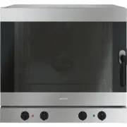
Page 8 - Description; General Description; Cooktop
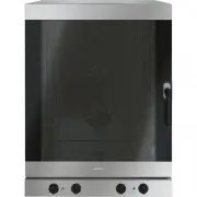
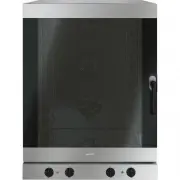
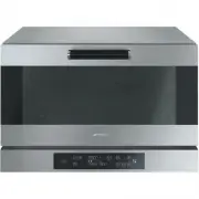
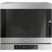
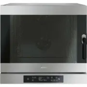
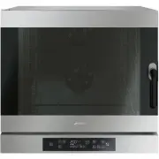
Description 10 2 Description 2.1 General Description 1 Cooktop 2 Control panel 3 Oven light 4 Seal 5 Door 6 Fan 7 Storage compartment Rack/tray support frames
Page 9 - Cooktop burner knobs
Description 11 EN 2.2 Cooktop AUX = AuxiliarySR = Semi-rapid R = RapidDUAL = Ultra rapid 2.3 Control panel 1 Cooktop burner knobs Useful for lighting and adjusting the cooktop burners.Press and turn the knobs anti-clockwise to the value to light the relative burners. Turn the knobs to the zone betwe...
Page 10 - Display
Description 12 3 Display Displays the current time, the selected cooking temperature, function and any time set. 4 Function knob This knob allows you to turn the appliance on and off and select the cooking function. 2.4 Other parts Cooling fan The fan cools the ovens and comes into operation during ...
Page 11 - Available accessories; WOK reduction pan stand
Description 13 EN 2.5 Available accessories WOK reduction pan stand Useful when using a wok. Tray rack To be placed over the top of the oven tray; for cooking foods which may drip. Oven tray Useful for collecting fat from foods placed on the rack above. Deep tray Useful for collecting fat from foods...
Page 12 - Rack
Description 14 Rack Useful for supporting containers with food during cooking. Rotisserie Useful for cooking chicken and all foods which require uniform cooking over their entire surface. Some models are not provided with all accessories. The accessories intended to come into contact with food are m...
Page 13 - Use; Danger of burns
Use 15 EN 3 Use 3.1 Instructions High temperature inside the oven during use Danger of burns • Keep the oven door closed during cooking. • Protect your hands by wearing oven gloves when handling food inside the oven cavity. • Do not touch the heating elements inside the oven. • Do not pour water dir...
Page 14 - A gas leak may cause an explosion.
Use 16 A gas leak may cause an explosion. If you smell gas or there are faults in the gas system:• Immediately turn off the gas supply or close the valve of the gas cylinder. • Immediately extinguish all naked flames and cigarettes. • Do not turn on power switches and do not remove plugs from power ...
Page 15 - Using the accessories; Reduction pan stands
Use 17 EN 3.3 Using the accessories Reduction pan stands The reduction pan stands have to be placed on the cooktop pan stands. Make sure they are properly placed. Tray rack The tray rack has to be inserted into the tray. In this way fat can be collected separately from the food which is being cooked...
Page 16 - Rotisserie
Use 18 Rotisserie 1. Insert the 4 bushes provided into the 4 holes in the corners of the deep tray and use a tool (such as a screwdriver) to screw them to the rings. 2. Place the rotisserie supports into the bushes as shown in the figure below. 3. Prepare the rotisserie rod with the food using the c...
Page 17 - Place the tray on the first runner (see
Use 19 EN 5. Place the tray on the first runner (see “General Description”). 6. Insert the end of the rod into the seat of the rotisserie motor on the left of the rear wall of the oven cavity. 7. To activate the rotisserie, turn the function knob to select the + function and set a cooking temperatur...
Page 18 - Using the cooktop; Practical tips for using the cooktop
Use 20 3.4 Using the cooktop All the appliance’s control and monitoring devices are located together on the front panel. The burner controlled by each knob is shown next to the knob. The appliance is equipped with an electronic ignition device. Simply press the knob and turn it anti-clockwise to the...
Page 19 - Display
Use 21 EN Correct positioning of the pan stands on the cooktop Before lighting the burners, make sure that the pan stands are positioned properly on the cooktop.Bear in mind that:• Each pan stand has its own position on the cooktop. • The raised part should always be placed towards the upstand of th...
Page 20 - Operating modes
Use 22 Operating modes Standby: When no function is selected, the display shows the current time . ON : When any function is activated, the display shows the set parameters such as the temperature, duration and temperature reached. Each time the temperature knob is pressed during a function, the par...
Page 21 - Setting the time
Use 23 EN Setting the time On the first use, or after a power failure, will flash on the appliance’s display. To be able to start any cooking function, the current time must be set.1. Turn the temperature knob to set the time displayed (keep the knob turned to increase or decrease it more quickly). ...
Page 22 - Functions list
Use 24 Functions list Eco This low energy consumption function is particularly suitable for cooking on a single shelf.Ideal when cooking meat, fish and vegetables. It is not recommended for foods that require proving.For greater energy savings and to reduce the time required, it is recommended to pu...
Page 23 - Timer
Use 25 EN Timer 1. Press the temperature knob once (twice if cooking is already in progress). The display shows and the indicator light flashes. 2. Turn the temperature knob to set the duration (from 1 minute to 4 hours). After a few seconds, the indicator light stops flashing and the countdown star...
Page 24 - Timed cooking
Use 26 Timed cooking 1. After selecting a cooking function and temperature, press the temperature knob three times. The display shows and the indicator light flashes. 2. Turn the temperature knob to the right or left to set the cooking duration from 00:01 to 12:59. Keep the knob turned to produce a ...
Page 25 - Programmed cooking
Use 27 EN 5. To turn off the buzzer, press or turn one of the two knobs or open the door. Modifying the data set during timed cooking During operation, it is possible to modify timed cooking duration: 1. When the indicator light is steady and cooking is in progress, press the temperature knob twice....
Page 27 - General advice
Use 29 EN Modifying the data set during programmed cooking During operation, it is possible to modify programmed cooking duration: 1. When the and indicator lights are lit steadily and the appliance is waiting to start cooking, press the temperature knob twice. The indicator light will start flashin...
Page 28 - Advice for defrosting and proving
Use 30 Advice for cooking desserts/pastries and biscuits • Use dark metal moulds: They help to absorb the heat better. • The temperature and the cooking time depend on the quality and consistency of the dough. • When cooking on multiple levels, food should ideally be positioned on the second and fou...
Page 29 - Special functions; Defrost by time
Use 31 EN 3.7 Special functions Defrost by time 1. Place the food to be heated inside the oven. 2. Press and turn the function knob to select the defrost by time function . 3. Turn the temperature knob to set the duration (from 1 to 99 minutes). 4. Press the temperature knob to confirm the set durat...
Page 30 - Sabbath mode
Use 32 Sabbath mode 1. Press and turn the function knob to select Sabbath mode . 2. Turn the temperature knob to modify the temperature of the function. 3. Press the temperature knob to confirm the set temperature. flashes. 4. Press the function knob to start Sabbath mode. 5. Keep the function knob ...
Page 31 - Defrost by weight
Use 33 EN Defrost by weight 1. Place the food to be heated inside the oven. 2. Press and turn the function knob to select the defrost by weight function indicated by and the illuminated food symbols . 3. Press the function knob to confirm the defrost by weight function. 4. Turn the function knob to ...
Page 32 - Automatic programs
Use 34 3.8 Automatic programs The automatic programs are divided into the type of foods to be cooked.1. Press and turn the function knob to select cooking with automatic programs indicated by and the illuminated food symbols . 2. Press the function knob to confirm cooking with automatic programs. 3....
Page 33 - Automatic programs table
Use 35 EN Automatic programs table MEAT (01 - 05) FISH (06 - 07) VEGETABLES (08 - 10) (1) When you grill food, it is recommended to cook it on both sides referring to the times indicated in the table. The longer length of time indicated always refers to the first side to be cooked starting from the ...
Page 34 - 5 Pan baked pizza
Use 36 DESSERTS/PASTRIES (11 - 13) BREAD - PIZZA - PASTA (14 -20) (2) The stone must be placed on the bottom of the oven cavity. Frozen pizzas of different weights cooked on the stone do not require different cooking times. Pr Subcategory Weight (g) Level Function Temperature (°C) Time (minutes) 11 ...
Page 35 - ON
Use 37 EN 3.9 Secondary menu The appliance also has a drop-down secondary menu allowing the user to:• Activate or deactivate the Child Lock.• Activate or deactivate Showroom mode (which disables all the heating elements so that only the control panel works). • Activate or deactivate the Low Power mo...
Page 36 - OFF
Use 38 To release the lock temporarily during cooking, hold the temperature knob down for 5 seconds. One minute after the last setting the lock will become active again. Showroom mode (for exhibitors only) This mode allows the appliance to deactivate all heating elements, while keeping the control p...
Page 37 - Keep Warm mode
Use 39 EN Low power mode (Eco-logic) This mode allows the appliance to limit the power used. Suitable for simultaneous use with further home appliances. HI: normal power. LO: low power. Keep Warm mode This mode allows the appliance to keep cooked food warm (at low temperatures) for approximately 1 h...
Page 38 - Using the storage compartment; Release the door of the storage
Use 40 Timed light mode (Eco-light) For greater energy savings, the light is turned off automatically one minute after the start of cooking. To prevent the appliance from turning off the light automatically after one minute set this mode to OFF. 3.10 Using the storage compartment The storage compart...
Page 39 - Cleaning and maintenance; Cleaning the appliance; Advice for cleaning the cooktop
Cleaning and maintenance 41 EN 4 Cleaning and maintenance 4.1 Instructions 4.2 Cleaning the appliance Advice for cleaning the cooktop To keep the surfaces in good condition, they should be cleaned regularly after use. Let them cool first. Cleaning the cooktop 1. Pour some non-abrasive detergent onto...
Page 40 - Cleaning the igniters and thermocouples; Cleaning the door; Removing the door
Cleaning and maintenance 42 Cleaning the igniters and thermocouples • If necessary, clean the igniters and thermocouples using a damp cloth. • If there are any dry residues, remove them with a toothpick or needle. 4.3 Cleaning the door Removing the door For easier cleaning, it is recommended to remo...
Page 41 - Removing the internal glass panels
Cleaning and maintenance 43 EN Removing the internal glass panels For easier cleaning, the internal glass panels of the door can be removed.1. Pull the rear part of the internal glass panel gently upwards, following the movement indicated by the arrows ( 1 ). 2. Remove the internal glass panel from ...
Page 42 - Cleaning the oven; Removing rack/tray support frames
Cleaning and maintenance 44 4.4 Cleaning the oven In order to keep your oven in the best possible condition, clean it regularly after letting it cool down.Do not allow food residues to dry inside the oven cavity because doing so could damage the enamel.Before cleaning, remove all the parts that can ...
Page 43 - Manually disengaging the door lock lever; Door lock lever activated; Move the door lock lever to the right
Cleaning and maintenance 45 EN Manually disengaging the door lock lever The door lock lever is located in the first slot on the left under the control panel, in the upper part of the front of the oven. During normal cleaning operations, the door lock lever may be activated accidentally. Door lock le...
Page 44 - Improper use
Cleaning and maintenance 46 Pyrolytic cleaning Preliminary operations Before starting the pyrolytic cycle:• Clean the internal glass panel following the usual cleaning instructions. • For very stubborn encrustations spray an oven cleaning product onto the glass (read the warnings on the product); le...
Page 45 - Setting of programmed pyrolytic cycle
Cleaning and maintenance 47 EN 2. Two minutes after the pyrolytic cycle has started, the door is locked (the door lock indicator light comes on) by a device that prevents the door from being opened. 3. At the end of the pyrolytic cycle, the door remains locked until the temperature inside the oven c...
Page 46 - Extraordinary maintenance; Replacing the internal light bulb
Cleaning and maintenance 48 4.5 Extraordinary maintenance Replacing the internal light bulb 1. Completely remove all accessories from inside the oven. 2. Remove the rack/tray support frames. 3. Remove the bulb cover using a tool (e.g. a screwdriver). 4. Slide out and remove the light bulb. 5. Fit th...
Page 47 - Seal maintenance recommendations
Cleaning and maintenance 49 EN Removing and installing the door seal (not on pyrolytic models) To remove the seal:• Release the hooks in the 4 corners and in the centre and pull the seal outwards. To install the seal:• Attach the hooks in the 4 corners and in the centre of the seal. Seal maintenance...
Page 48 - The display is completely off:
Cleaning and maintenance 50 The display is completely off: • Check the mains power supply.• Check whether an omnipolar switch upstream of the appliance supply line is in the “ON” position. The controls do not respond: • Check whether it has been set in “child lock” mode (for further details see “Sec...
Page 49 - Installation; Minimum clearance to combustible surfaces; Freestanding cooker
Installation 51 EN 5 Installation 5.1 Minimum clearance to combustible surfaces Freestanding cooker A 600 mm (Overhead) measured from the highest part of the highest burner and 750 mm for an exhaust fan. B 200 mm (Vertical combustible surface) measured form the edge of the nearest burner. C 10 mm (H...
Page 50 - The regulator supplied must be fitted; Gas Approval onsulting Pty Ltd.
Installation 52 separate fitting in the case of ULPG (propane) appliances.Connection of the appliance to the gas supply must be in accordance with the requirements of AS5601. A ½” BSP connector at the inlet is recommended and the gas supply line to the appliance must be of adequate length to allow s...
Page 51 - Connection to liquid gas
Installation 53 EN 4. If the pressure is 2.75kPa, reassemble the burner and perform the final checks as per this instruction manual. 5. If the pressure is not 2.75kPa, disconnect the appliance and check/adjust/replace the LPG cylinder regulator(s) as appropriate in accordance with AS/NZS5601. Connec...
Page 53 - Adaptation to different types of gas
Installation 55 EN 4. Screw the extension pipe assembly C to the gas connector D of the appliance, placing the seal provided 2 between them. 5. Apply insulating material to the thread of the extension pipe assembly C , then tighten the hose E . Adaptation to different types of gas In case of operati...
Page 54 - Adjusting the minimum setting for LPG
Installation 56 Adjusting the minimum setting for natural or city gas Light the burner and turn it to the minimum position. Extract the gas valve knob and turn the adjustment screw next to the valve stem (depending on the model) until the correct minimum flame is achieved.Refit the knob and verify t...
Page 55 - Burner and nozzle characteristics table; Heavy appliance
Installation 57 EN Burner and nozzle characteristics table 5.3 Positioning Dimensions * Minimum cabinet width ( =A ). NG 1.0 kPa AUX SR R DUAL int + ext Nominal gas consumption (MJ/h) 3.9 7.5 12 15.2 Injector (1/100) 90 120 155 80 + 165 ULPG 2.75 kPa AUX SR R DUAL int. + ext. Nominal gas consumption...
Page 56 - General information; B - Class 2 subclass 1
Installation 58 General information This appliance may be installed next to walls, one of which must be higher than the worktop, at a minimum distance of X mm from the side of the appliance, as shown in figures A and C relative to the installation classes.Any wall units positioned above the worktop ...
Page 57 - Positioning and levelling
Installation 59 EN Positioning and levelling • After making the gas and electrical connections, screw on the four feet supplied with the appliance. The appliance must sit level on the floor to ensure stability:• Screw or unscrew the bottom part of the foot until the appliance is stable and level on ...
Page 58 - Align the base of the hook on the
Installation 60 3. Assemble the fastening bracket. 4. Align the base of the hook on the fastening bracket with the base of the slot on the wall fastening plate. 5. Align the base of the fastening bracket so that it reaches the floor and tighten the screws to fix it in position. 6. The distance from ...
Page 59 - Move the bracket against the wall and
Installation 61 EN 7. Move the bracket against the wall and mark the position of the holes to be drilled in the wall. 8. After drilling the holes in the wall, use wall plugs and screws to fasten the bracket to the wall. 9. Push the cooker towards the wall and at the same time, insert the bracket in ...
Page 60 - Place the plinth in the front bottom part
Installation 62 2. Place the plinth in the front bottom part of the appliance and line up the holes on the side of the front plinth with the holes on the base of the appliance. 3. Fasten the front plinth to the appliance using the screws that were previously removed. Installing the side plinth After...
Page 61 - Assembling the upstand
Installation 63 EN 3. Insert the tabs of the side plinth into the slots on the back of the front plinth. 4. Line up the holes of the side plinth with the hole at the rear of base of the appliance. 5. Fasten the side plinth to the appliance using the screw that was previously removed. 6. Repeat the a...
Page 62 - Electrical connection
Installation 64 5.4 Electrical connection General information Check the grid characteristics against the data indicated on the plate.The identification plate bearing the technical data, serial number and brand name is visibly positioned on the appliance.Do not remove this plate for any reason.Perfor...
Page 63 - Accessing the terminal board
Installation 65 EN Accessing the terminal board To connect the power cable, you need to access the terminal board on the rear casing:1. Remove the screws that fasten the access plate to the rear casing. 2. Rotate the plate slightly and remove it from its seat. 3. Install the power cable. 4. When fin...
Page 64 - Fixed connection; Instructions for the installer; DO NOT
Installation 66 Fixed connection Fit the power line with an omnipolar circuit breaker in compliance with installation regulations.The circuit breaker should be located near the appliance and in an easily reachable position. Connection with plug and socket Make sure that the plug and socket are of th...


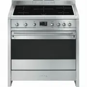
 Smeg A11X-7
User Manual
Smeg A11X-7
User Manual
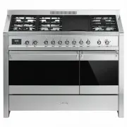
 Smeg A11XPY-9
User Manual
Smeg A11XPY-9
User Manual
 Smeg A1PYID-7
User Manual
Smeg A1PYID-7
User Manual
 Smeg A1PYID-9
User Manual
Smeg A1PYID-9
User Manual
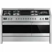
 Smeg A3AU-81
User Manual
Smeg A3AU-81
User Manual
 Smeg A5AU-81
User Manual
Smeg A5AU-81
User Manual
 Smeg ALFA1035EH
User Manual
Smeg ALFA1035EH
User Manual
 Smeg ALFA1035EHDS
User Manual
Smeg ALFA1035EHDS
User Manual
 Smeg ALFA1035EHT
User Manual
Smeg ALFA1035EHT
User Manual
 Smeg ALFA1035H
User Manual
Smeg ALFA1035H
User Manual
 Smeg ALFA1035H-2
User Manual
Smeg ALFA1035H-2
User Manual
 Smeg ALFA420EH
User Manual
Smeg ALFA420EH
User Manual
 Smeg ALFA420EHDS
User Manual
Smeg ALFA420EHDS
User Manual
 Smeg ALFA420EHT
User Manual
Smeg ALFA420EHT
User Manual
 Smeg ALFA625EH
User Manual
Smeg ALFA625EH
User Manual
 Smeg ALFA625EHDS
User Manual
Smeg ALFA625EHDS
User Manual
 Smeg ALFA625EHT
User Manual
Smeg ALFA625EHT
User Manual
 Smeg ALFA625H
User Manual
Smeg ALFA625H
User Manual
 Smeg ALFA625H-2
User Manual
Smeg ALFA625H-2
User Manual
 Smeg ALFA625HR-2
User Manual
Smeg ALFA625HR-2
User Manual