Makita SP6000 - Manuals
Makita SP6000 Circular Saw – Manual in PDF format online.
Manuals:
Manual Makita SP6000


Summary
2 ENGLISH (Original instructions) SPECIFICATIONS Model SP6000 Blade diameter 165 mm at 90° 56 mm at 45° 40 mm Max. cutting depth at 48° 38 mm No load speed (min -1 ) 2,000 - 5,200 Overall length 341 mm Net weight 4.4 kg Safety class /II • Due to our continuing programme of research and development, ...
4 power tool will do the job better and safer at the rate for which it was designed. 18. Do not use the power tool if the switch does not turn it on and off. Any power tool that cannot be controlled with the switch is dangerous and must be repaired. 19. Disconnect the plug from the power source and/...
5 toward the operator; − if the blade becomes twisted or misaligned in the cut, the teeth at the back edge of the blade can dig into the top surface of the wood causing the blade to climb out of the kerf and jump back toward the operator. Kickback is the result of saw misuse and/or incorrect operati...
Makita Circular Saws Manuals
-
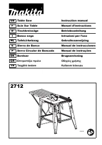 Makita 2712
User Manual
Makita 2712
User Manual
-
 Makita 4131
User Manual
Makita 4131
User Manual
-
Makita 4131
Manual
-
 Makita 5104
User Manual
Makita 5104
User Manual
-
Makita 5104
Manual
-
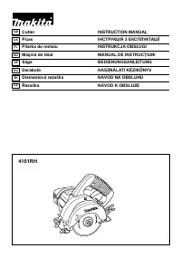 Makita 4101 RH
User Manual
Makita 4101 RH
User Manual
-
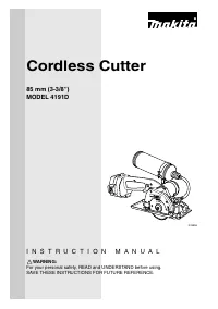 Makita 4191DWA
User Manual
Makita 4191DWA
User Manual
-
Makita 4191DWA
Manual
-
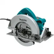 Makita 5007F
User Manual
Makita 5007F
User Manual
-
Makita 5007F
Manual
-
 Makita 5007FA
User Manual
Makita 5007FA
User Manual
-
Makita 5007FA
Manual
-
 Makita 5007MG
User Manual
Makita 5007MG
User Manual
-
Makita 5007MG
Manual
-
 Makita 5007NK
User Manual
Makita 5007NK
User Manual
-
 Makita 5008MGA
User Manual
Makita 5008MGA
User Manual
-
Makita 5008MGA
Manual
-
 Makita 5057KB
User Manual
Makita 5057KB
User Manual
-
Makita 5057KB
Manual
-
 Makita 5143R
User Manual
Makita 5143R
User Manual