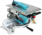
Makita LF1000 - Manuals
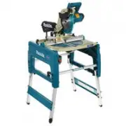
Manual Makita LF1000


Summary
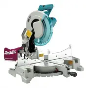
P 2 / 30 S tandard equipment Assorted TCT saw blades Note: The standard equipment for the tool shown above may differ by country. TCT saw blade ......... 1 pcVise ass'y ................. 1 pcDust bag ass'y .......... 1 pcRuler ass'y ................ 1 pc Box wrench 13-3 ...... 1 pcPush stick ..........
P 3 / 30 R epair [1] NECESSARY REPAIRING TOOLS CAUTION: Remove the saw blade from the machine for safety before repair/ maintenance ! Code No. 1R003 Retaining ring S Pliers ST-2N Removing Retaining ring from Safety cover 1R207 45 degree Set square Setting the miter/bevel angle of saw blade to 45 deg...
P 10/ 30 R epair [3] DISASSEMBLY/ASSEMBLY Fig. 23 Fig. 24 Fig. 25 ASSEMBLING [3] -5. Blade Case Section (cont.) Slide Sleeve 13 as far as possible toward Steel ball 6. At this time, the distance between Sleeve 13 and the neck ofKnob 40 will be about 7mm. While keeping the distance, secure Connecting...
Makita Miter Saws Manuals
-
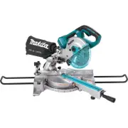
 Makita GSL02Z
User Manual
Makita GSL02Z
User Manual
-
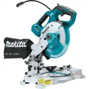
 Makita GSL03Z
User Manual
Makita GSL03Z
User Manual
-
 Makita GSL04M1
User Manual
Makita GSL04M1
User Manual
-
 Makita LH1040
User Manual
Makita LH1040
User Manual
-
 Makita LH1040F
User Manual
Makita LH1040F
User Manual
-
 Makita LS0815F
User Manual
Makita LS0815F
User Manual
-
 Makita LS1018
User Manual
Makita LS1018
User Manual
-
 Makita LS1018A-93681
User Manual
Makita LS1018A-93681
User Manual
-
 Makita LS1019L
User Manual
Makita LS1019L
User Manual
-
 Makita LS1019LX
User Manual
Makita LS1019LX
User Manual
-
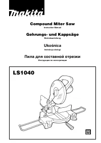 Makita LS1040
User Manual
Makita LS1040
User Manual
-
Makita LS1040
Manual
-
 Makita LS1219L
User Manual
Makita LS1219L
User Manual
-
 Makita LS1219LX
User Manual
Makita LS1219LX
User Manual
-
 Makita LS1221
User Manual
Makita LS1221
User Manual
-
Makita LS1221
Manual
-
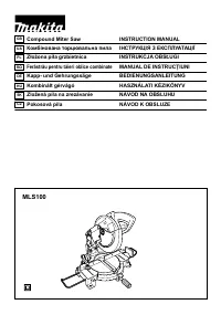 Makita MLS100
User Manual
Makita MLS100
User Manual
-
Makita MLS100
Manual
-
 Makita XSL02Z
User Manual
Makita XSL02Z
User Manual
-
 Makita XSL05Z
User Manual
Makita XSL05Z
User Manual