Makita HR2641X1 - Manuals
User Manual Makita HR2641X1


Summary
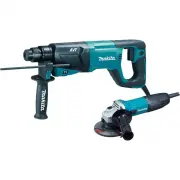
2 ENGLISH (Original instructions) SPECIFICATIONS Model HR2631F HR2631FT HR2641 HR2320T HR2630 HR2630T Concrete 26 mm 23 mm 26 mm Core bit 68 mm Diamond core bit (dry type) 80 mm 70 mm 80 mm Steel 13 mm Capacities Wood 32 mm No load speed 0 - 1,200 min -1 0 - 1,100 min -1 0 - 1,200 min -1 Blows per m...
4 GEB007-7 ROTARY HAMMER SAFETY WARNINGS 1. Wear ear protectors. Exposure to noise can cause hearing loss. 2. Use auxiliary handle(s), if supplied with the tool. Loss of control can cause personal injury. 3. Hold power tool by insulated gripping surfaces, when performing an operation where the cutti...
5 1 015337 To turn on the lamp, pull the trigger. Release the trigger to turn it off. NOTE: • Use a dry cloth to wipe the dirt off the lens of lamp. Be careful not to scratch the lens of lamp, or it may lower the illumination. • Do not use thinner or gasoline to clean the lamp. Such solvents may dam...
Makita Hammer Drills Manuals
-
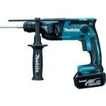 Makita DHR165RME
User Manual
Makita DHR165RME
User Manual
-
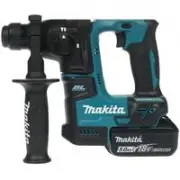 Makita DHR171RTJ
User Manual
Makita DHR171RTJ
User Manual
-
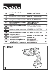 Makita DHR182ZWJ
User Manual
Makita DHR182ZWJ
User Manual
-
 Makita DHR202RFJ
User Manual
Makita DHR202RFJ
User Manual
-
 Makita DHR241RFE
User Manual
Makita DHR241RFE
User Manual
-
 Makita DHR241RFJ
User Manual
Makita DHR241RFJ
User Manual
-
 Makita DHR242RFE
User Manual
Makita DHR242RFE
User Manual
-
 Makita DHR242Z
User Manual
Makita DHR242Z
User Manual
-
 Makita DHR263Z
User Manual
Makita DHR263Z
User Manual
-
 Makita DHR282ZJ
User Manual
Makita DHR282ZJ
User Manual
-
 Makita GPH01Z
User Manual
Makita GPH01Z
User Manual
-
 Makita GPH02D
User Manual
Makita GPH02D
User Manual
-
 Makita HR001GZ
User Manual
Makita HR001GZ
User Manual
-
 Makita HR004GZ
User Manual
Makita HR004GZ
User Manual
-
 Makita HR140DWAJ
User Manual
Makita HR140DWAJ
User Manual
-
 Makita HR140DZ
User Manual
Makita HR140DZ
User Manual
-
 Makita HR166DWAJ
User Manual
Makita HR166DWAJ
User Manual
-
 Makita HR166DZ
User Manual
Makita HR166DZ
User Manual
-
 Makita HR1840
User Manual
Makita HR1840
User Manual
-
 Makita HR1841F
User Manual
Makita HR1841F
User Manual