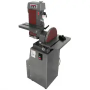
Jet 708596K - Manuals
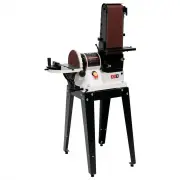
User Manual Jet 708596K


Summary
3 WARNING Wear eye protection. Always keep guards in place and in proper operating condition. Do not operate the machine without the guards for any reason. This disc/belt sander is intended to be used with wood and wood products only. Use of this disc/belt sander and a dust collector with metal prod...
4 • ALWAYS DISCONNECT THE MACHINE FROM THE POWER SOURCE BEFORE SERVICING. • REDUCE THE RISK OF UNINTENTIONAL STARTING. Make sure the switch is in the off positionbefore plugging in. • USE RECOMMENDED ACCESSORIES. The use of accessories and attachments notrecommended by JET may cause hazards or risk ...
5 Grounding Instructions Caution: This tool must be grounded while in use to protect the operator from electric shock. In the ev ent of a malfunction or breakdown, grounding prov ides a path of least resistance for electriccurrent to reduce the risk of electric shock. This tool is equipped with an e...
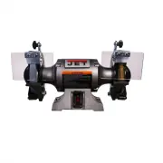
Jet Grinding Machines Manuals
-
 Jet 414551
User Manual
Jet 414551
User Manual
-
 Jet 414600
User Manual
Jet 414600
User Manual
-
 Jet 414610
User Manual
Jet 414610
User Manual
-
 Jet 577003
User Manual
Jet 577003
User Manual
-
 Jet 577004
User Manual
Jet 577004
User Manual
-
 Jet 577101
User Manual
Jet 577101
User Manual
-
 Jet 577102
User Manual
Jet 577102
User Manual
-
 Jet 577103
User Manual
Jet 577103
User Manual
-
 Jet 577126
User Manual
Jet 577126
User Manual
-
 Jet 577128
User Manual
Jet 577128
User Manual
-
 Jet 577248
User Manual
Jet 577248
User Manual
-
 Jet 577400
User Manual
Jet 577400
User Manual
-
 Jet 577405
User Manual
Jet 577405
User Manual
-
 Jet 577408
User Manual
Jet 577408
User Manual
-
 Jet 577436
User Manual
Jet 577436
User Manual
-
 Jet 577634
User Manual
Jet 577634
User Manual
-
 Jet 578008
User Manual
Jet 578008
User Manual
-
 Jet 578010
User Manual
Jet 578010
User Manual
-
 Jet 578218
User Manual
Jet 578218
User Manual
-
 Jet 578248
User Manual
Jet 578248
User Manual