Jet 577248 - User Manual
Jet 577248 Grinding Machine – User Manual, read for free online in PDF format. We hope this helps you resolve any issues you may have. If you have further questions, please contact us through the contact form.


Table of Contents:
- Page 4 – Table of contents; Section
- Page 5 – About this manual
- Page 6 – Specifications
- Page 7 – Mounting hole dimensions
- Page 8 – Machine dimensions/work area
- Page 9 – Carton contents
- Page 10 – Setup and assembly
- Page 11 – Sanding table; Sanding tool rest
- Page 12 – Electrical connections; GROUNDING INSTRUCTIONS; Extension cords
- Page 13 – Adjustments
- Page 14 – Operation; Operating controls
- Page 15 – Precautions; Wheel grinding; Installing/replacing sanding belt; Care of grinding wheels
- Page 16 – Changing wheels; Wheel balancing; Adjusting concentricity
- Page 18 – Optional accessories
- Page 19 – Troubleshooting IBGB series Sander/Grinder; General mechanical and electrical problems
- Page 20 – Digital readout error codes (Variable speed models)
- Page 21 – Replacement Parts
- Page 22 – IBGB-248 Sander/Grinder – Exploded View
- Page 25 – IBGB-248VS Sander/Grinder – Exploded View
- Page 26 – IBGB-248VS Sander/Grinder – Parts List; Index No Part No
- Page 28 – IBGB-436 Sander/Grinder – Exploded View
- Page 31 – IBGB-436VS Sander/Grinder – Exploded View
- Page 32 – IBGB-436VS Sander/Grinder – Parts List
- Page 34 – Electrical Connections; Wiring diagram for IBGB-248 and IBGB-436; Input Power
- Page 35 – Warranty and service
1
Operating Instructions and Parts Manual
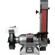
8-inch Grinder with Belt Sander
Models IBGB-248/248VS/436/436VS
JET
427 New Sanford Road
Part No. M-577248
LaVergne, Tennessee 37086
Edition 4 10/2019
Ph.: 800-274-6848
ECR 191025080920
www.jettools.com
Copyright © 2019 JET
Variable speed model IBGB-436VS shown
for models with serial no. 19120001 and higher.
This .pdf document is bookmarked
"Loading the manual" means you need to wait until the file loads and becomes available for online reading. Some manuals are very large, and the time they take to appear depends on your internet speed.
Summary
4 2.0 Table of contents Section Page 1.0 IMPORTANT SAFETY INSTRUCTIONS ....................................................................................................... 2 2.0 Table of contents ......................................................................................................
5 14.1 Wiring diagram for IBGB-248 and IBGB-436 ......................................................................................... 34 14.2 Wiring diagram for IBGB-248VS and IBGB-436VS ................................................................................ 34 15.0 Warranty and ser...
6 4.0 Specifications Table 1 Stock number 577248 578248 577436 578436 Model number IBGB-248VS IBGB-248 IBGB-436VS IBGB-436 Motor and Electricals Motor Type Induction, with inverter Induction, capacitor start, centrifugal switch Induction, with inverter Induction, capacitor start, centrifugal switch ...