Jet 577408 - User Manual
Jet 577408 Grinding Machine – User Manual, read for free online in PDF format. We hope this helps you resolve any issues you may have. If you have further questions, please contact us through the contact form.


Table of Contents:
- Page 2 – WARNING – To reduce risk of injury:
- Page 3 – SAVE THESE INSTRUCTIONS
- Page 4 – Table of contents; Section
- Page 5 – About this manual
- Page 6 – Specifications
- Page 7 – Mounting hole dimensions
- Page 8 – Setup and assembly; Unpacking; Securing the buffer; Electrical connections
- Page 9 – GROUNDING INSTRUCTIONS; Extension cords; Voltage conversion
- Page 10 – Operation; General procedure; Changing Wheels
- Page 11 – Wheel balancing; Adjusting concentricity; Buffer maintenance
- Page 12 – Troubleshooting IBG-SSB series Buffers
- Page 13 – Optional accessories
- Page 14 – IBG-8SSB Buffer – Exploded View
- Page 15 – IBG-8SSB Buffer – Parts List; Description
- Page 16 – IBG-10SSB Buffer – Exploded View
- Page 17 – IBG-10SSB Buffer – Parts List
- Page 18 – IBG-12SSB Buffer – Exploded View
- Page 19 – IBG-12SSB Buffer – Parts List
- Page 20 – Electrical Connections; Wiring diagram for IBG-8SSB
- Page 21 – Wiring diagram for IBG-10SSB
- Page 22 – Wiring diagram for IBG-12SSB
- Page 23 – Warranty and Service
JET
427 New Sanford Road
LaVergne, Tennessee 37086
Ph.: 800-274-6848
www.powermatic.com
Part No. M-577408
Edition 1 1
2
/2019
Copyright © 2019 Powermatic
Operating Instructions and Parts Manual
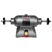
Industrial Buffing Machines
Models IBG-8SSB, IBG-10SSB, IBG-12SSB
IBG-8SSB
(includes wheels)
IBG-10SSB
IBG-12SSB
This .pdf document is bookmarked
"Loading the manual" means you need to wait until the file loads and becomes available for online reading. Some manuals are very large, and the time they take to appear depends on your internet speed.
Summary
2 1.0 IMPORTANT SAFETY INSTRUCTIONS WARNING – To reduce risk of injury: 1. Read and understand the entire owner's manual before attempting assembly or operation. 2. Read and understand the warnings posted on the machine and in this manual. Failure to comply with all of these warnings may cause serio...
3 32. Use proper extension cord. Make sure your extension cord is in good condition. When using an extension cord, be sure to use one heavy enough to carry the current your product will draw. An undersized cord will cause a drop in line voltage resulting in loss of power and overheating. Table 2 (se...
4 2.0 Table of contents Section Page 1.0 IMPORTANT SAFETY INSTRUCTIONS ....................................................................................................... 2 2.0 Table of contents ......................................................................................................