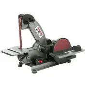
Jet 708447 - Manuals
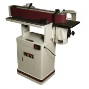
User Manual Jet 708447


Summary
2 Warranty and Service Walter Meier (Manufacturing) Inc., warrants every product it sells. If one of our tools needs service or repair, one of our Authori zed Service Centers located throughout the United States can give you quick service. In most cases, any of these Walter Meier Authorized Service ...
3 Table of Contents Warranty and Ser vice..........................................................................................................................2 Table of Contents ........................................................................................................................
7 Unpacking Upon delivery, open s hipping containers and c heck that all parts are in good condition. Any damage should be reported to your distributor and s hipping agent immediately. Before proceeding f urther, read your manual and familiarize yourself thoroughly with assembly, maintenance and saf...
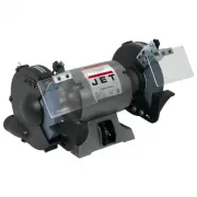
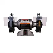
Jet Grinding Machines Manuals
-
 Jet 414551
User Manual
Jet 414551
User Manual
-
 Jet 414600
User Manual
Jet 414600
User Manual
-
 Jet 414610
User Manual
Jet 414610
User Manual
-
 Jet 577003
User Manual
Jet 577003
User Manual
-
 Jet 577004
User Manual
Jet 577004
User Manual
-
 Jet 577101
User Manual
Jet 577101
User Manual
-
 Jet 577102
User Manual
Jet 577102
User Manual
-
 Jet 577103
User Manual
Jet 577103
User Manual
-
 Jet 577126
User Manual
Jet 577126
User Manual
-
 Jet 577128
User Manual
Jet 577128
User Manual
-
 Jet 577248
User Manual
Jet 577248
User Manual
-
 Jet 577400
User Manual
Jet 577400
User Manual
-
 Jet 577405
User Manual
Jet 577405
User Manual
-
 Jet 577408
User Manual
Jet 577408
User Manual
-
 Jet 577436
User Manual
Jet 577436
User Manual
-
 Jet 577634
User Manual
Jet 577634
User Manual
-
 Jet 578008
User Manual
Jet 578008
User Manual
-
 Jet 578010
User Manual
Jet 578010
User Manual
-
 Jet 578218
User Manual
Jet 578218
User Manual
-
 Jet 578248
User Manual
Jet 578248
User Manual