Page 3 - SAVE THESE INSTRUCTIONS
3 28. Keep safety guards in place at all times when the machine is in use. If removed for maintenance purposes, use extreme caution and replace the guards immediately after completion of maintenance. 29. Check damaged parts. Before further use of the machine, a guard or other part that is damaged sh...
Page 4 - Table of contents; Section
4 2.0 Table of contents Section Page 1.0 IMPORTANT SAFETY INSTRUCTIONS ....................................................................................................... 2 2.0 Table of contents ......................................................................................................
Page 5 - About this manual
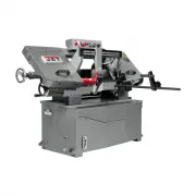
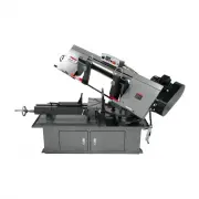
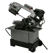
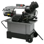
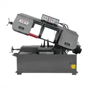
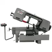
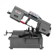
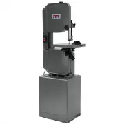
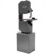
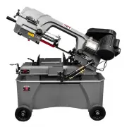
5 3.0 About this manual This manual is provided by JET, covering the safe operation and maintenance procedures for a JET Model HBS-916EVS and HBS-1018EVS Horizontal Band Saw. This manual contains instructions on installation, safety precautions, general operating procedures, maintenance instructions...
Page 6 - Specifications
6 4.0 Specifications Table 1 Stock number 424469 424470 Model number HBS-916EVS HBS-1018EVS Motor and Electricals Main motor type Totally-enclosed, fan-cooled, AC induction Horsepower 1-1/2 HP (1.1 kW) 2 HP (1.5 kW) Phase 3 phase Voltage 230V Cycle 60 Hz Listed FLA (full load amps) 5 A 6.5 A Startin...
Page 8 - Setup and assembly; Shipping contents; Motor
8 Read and understand the entire contents of this manual before attempting assembly or operation. Failure to comply may cause serious injury. 5.0 Setup and assembly 5.1 Shipping contents NOTE: Accessories are shipped in the coolant reservoir beneath the chip tray. To access, remove two wing screws a...
Page 9 - V-belt and pulley cover; Control box; Electrical connections; Connecting motor cable
9 6. Attach motor tilt plate (B, Figure 5-3) to motor bracket using the provided locking handle (C, Figure 5-3) with lock washer and flat washer. Figure 5-3: motor locking handle Note: Locking handle (C) is adjustable. Pull out on handle and rotate it on the pin to a more convenient position, then r...
Page 10 - Extension cords; Adjustments; Removing and installing blades
10 installed and grounded in accordance with all local codes and ordinances. Do not modify the plug provided - if it will not fit the outlet, have the proper outlet installed by a qualified electrician. Improper connection of the equipment-grounding conductor can result in a risk of electric shock. ...
Page 11 - Blade guide bracket adjustment
11 7. Remove blade from both wheels and out of each blade guide. 8. Make sure teeth of new blade are pointing in proper direction of travel. Work blade all the way up into blade guide bearings and guide blocks with back of blade against rear support bearing. See sect. 7.5 for further details. 9. Pos...
Page 12 - Blade guide adjustments; Rear support bearing; Guide blocks and bearings; Test cutting to verify adjustment
12 7.5 Blade guide adjustments Tools required: 5mm, 6mm hex wrenches 19mm open-end wrench Proper adjustment of blade guide bearings is critical to efficient operation of the saw. The band saw is shipped with blade tensioned and blade guides properly set by the manufacturer, but should be confirmed b...
Page 13 - Bow weight adjustment; Vise adjustments
13 Figure 7-4: test cut 7.7 Bow weight adjustment Bow weight has been properly set by the manufacturer and should not require attention. If future adjustment becomes necessary, due to part replacement or other contingency, proceed as follows: 1. Disconnect machine from power source. 2. Raise bow to ...
Page 14 - Operating controls; Prior to Operation
14 3. Make sure bolts on left/floating vise (M 2 ) are loosened. Use handwheel to push vise against workpiece until it conforms to workpiece angle. Tighten bolts. 4. To expand clamping capacity, remove fixed jaw from inner holes and install it in outer holes. 7.9 Work stop adjustment The work stop a...
Page 15 - Operation; Blade selection
15 10.0 Operation General operating procedure: 1. Turn feed knob to off. 2. Raise bow and set desired feed rate. 3. Position workpiece; make sure it is secure within vise. Make sure left blade guide bracket is adjusted as close as possible to left vise jaw. 4. Press Start to begin blade movement. Ac...
Page 16 - Lubrication; Gear box oil change; Servicing cutting fluid; Sheave alignment
16 11.1 Lubrication See sect. 11.4, Table 3, for lubrication chart. Blade guide ball bearings are permanently lubricated and sealed; they require no further lubrication. Apply a light coat of machine oil to moving parts as needed. Periodically apply light coat of machine oil to exposed metal surface...
Page 17 - Lubrication schedule; Blade speed recommendations
17 11.4 Lubrication schedule Item or location Recommended lubricant Frequency Vise lead screw Light machine oil Monthly Hydraulic cylinder pivot areas Light machine oil Every 6 months Blade tension shaft General purpose grease Every 6 months Blade brush shaft Light machine oil As needed Front slide ...
Page 19 - Replacement Parts
19 Symptom Possible Cause Correction* Frequent blade breakage (cont.) Blade rubs heavily on wheel shoulder. Adjust blade tracking. Tooth pitch too coarse for material. Use appropriate blade for material. Teeth in contact with workpiece before saw is started. Start motor before blade contacts workpie...
Page 20 - HBS-916EVS & 1018EVS – Bed and Base Assembly – Exploded View
20 14.1.1 HBS-916EVS & 1018EVS – Bed and Base Assembly – Exploded View
Page 21 - HBS-916EVS – Bow Assembly – Exploded View
21 14.1.2 HBS-916EVS – Bow Assembly – Exploded View
Page 22 - HBS-1018EVS – Bow Assembly – Exploded View
22 14.1.3 HBS-1018EVS – Bow Assembly – Exploded View
Page 29 - HBS-916EVS & 1018EVS – Gear Speed Reducing Box – Exploded View
29 14.2.1 HBS-916EVS & 1018EVS – Gear Speed Reducing Box – Exploded View
Page 30 - HBS-916EVS & 1018EVS – Gear Speed Reducing Box – Parts List; Description
30 14.2.2 HBS-916EVS & 1018EVS – Gear Speed Reducing Box – Parts List Index No. Part No. Description Size Qty .................. HBS916W-94G ......... Gear Box Assembly (includes #1 thru 23) ............... ...................................... 1 1 ................ HBS916W-94-01 ....... Oil Sea...
Page 32 - Warranty and service
32 16.0 Warranty and service JET warrants every product it sells against manufacturers’ defects. If one of our tools needs service or repair, please contact Technical Service by calling 1-800-274-6846, 8AM to 5PM CST, Monday through Friday. Warranty Period The general warranty lasts for the time per...