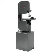
Page 2 - Warranty and Service
2 1.0 Warranty and Service JET warrants every product it sells against manufacturers’ defects. If one of our tools needs service or repair, please contact Technical Service by calling 1-800-274-6846, 8AM to 5PM CST, Monday through Friday. Warranty Period The general warranty lasts for the time per...
Page 3 - Table of contents; Section
3 2.0 Table of contents Section Page 1.0 Warranty and Service ..................................................................................................................................... 2 2.0 Table of contents ...............................................................................
Page 5 - About this manual; Specifications
5 Familiarize yourself with the following safety notices used in this manual: This means that if precautions are not heeded, it may result in minor injury and/or possible machine damage. This means that if precautions are not heeded, it may result in serious, or even fatal, injury. 4.0 About thi...
Page 6 - Assembly
6 6.0 Uncrating and Cleanup NOTE: Read and understand the entire manual before attempting setup or operation. 1. Finish uncrating the saw and inspect for damage. Should any have occurred, contact your local distributor. 2. Remove all bolts attaching machine to shipping base. 3. Leave packing mate...
Page 7 - Electrical Connections; Controls; Prior to Operation
7 11. Tension the v-belt by pushing down on the motor and tightening the lock handle on the motor tilt plate. Correct tension is achieved when finger pressure between the two pulleys causes approximately a 1/2” deflection. 12. Close pulley cover door and fasten with lock knob. 13. Fasten work sto...
Page 8 - Adjustments; Adjusting vise square to blade; Adjusting feed rate
8 6. Select proper speed and feed rate for material being cut. Consult Machinery’s Handbook or similar source for speed and feed charts. 7. Material to be cut must be securely held in vise. 8. Check to see that coolant level is adequate and turn on coolant pump if material to be cut requires it. ...
Page 9 - Blade tracking adjustment
9 Figure 7 6. Loosen lock knob (A, Figure 8) and slide left blade guide arm (B, Figure 8) to the right as far as possible. Figure 8 7. Remove old blade from both wheels and out of each blade guide. Even dull blades are sharp to the skin. Use extra caution handling bandsaw blades. 8. Install new b...
Page 11 - Angle adjustment; Vise adjustment
11 12.10 Angle adjustment To swivel the saw arm up to a 45° angle: 1. Disconnect machine from power source. 2. Pull the handle (A, Figure 13) toward the front of the saw. 3. Rotate the upper assembly to the desired angle. 4. Push the handle back toward the rear of the saw to lock the upper assembl...
Page 12 - Maintenance; Lubrication; Replacement Parts
12 1. Loosen adjustable handle (index #219,221) to desired location. 2. Set the vise to desired angle, reinstall nuts and tighten the nut and bolt assemblies. 3. Adjust the movable vise parallel to the fixed vise by loosening bolt (A, Figure 17), adjusting to parallel, and tightening bolt. Figure ...
Page 13 - MBS-1014W – Base and Bed Assembly – Exploded View
13 14.1.1 MBS-1014W – Base and Bed Assembly – Exploded View
Page 14 - MBS-1014W – Bow Assembly – Exploded View
14 14.1.2 MBS-1014W – Bow Assembly – Exploded View
Page 15 - Parts List for MBS-1014W Band Saw; Index No Part No
15 14.1.3 Parts List for MBS-1014W Band Saw Index No Part No Description Size Qty 1A .............. MBS1014W-1AG ....... Base ........................................................................ ...................................... 1 2 ................ Ts-1492071 ............... Hex Cap Bolt...
Page 20 - MBS-1014W – Gear Speed Reducer Assembly – Exploded View
20 14.2.1 MBS-1014W – Gear Speed Reducer Assembly – Exploded View
Page 21 - MBS-1014W – Gear Speed Reducer Assembly – Parts List
21 14.2.2 MBS-1014W – Gear Speed Reducer Assembly – Parts List Index No Part No Description Size Qty 1 ................ HBS916W-94-01 ....... Oil Seal .................................................................... 35x55x8 mm ................. 1 2 ................ BB-30207 .................. ...
Page 22 - Electrical Connections – 1 Phase; Main Motor
22 15.0 Electrical Connections 15.1.1 Electrical Connections – 1 Phase 15.1.2 Electrical Panel Layout – 1 Phase Main Motor Pump Motor