Page 2 - Table of contents
Overview About your new thermostat ................................................................... 1Controls ................................................................................................. 2Display....................................................................................
Page 3 - About your new thermostat; Do you need assistance?
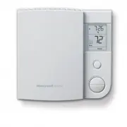
RLV4305 1 This thermostat is designed to control an electric heating system such as abaseboard heater, a radiant ceiling, a convector or a fan-forced heater. The thermostat CANNOT be used with: • a resistive load under 0.83 A • a resistive load over 14.6 A • a system driven by a contactor or a relay...
Page 4 - Controls
Owner’s Guide 2 Controls Mode button (see pages 8 & 10) Day button Hour button Program button Minute button Up and Down buttons Return button Backlit screen * * The screen is backlit for 12 seconds when you press any button. 69-2613ES-01.book Page 2 Thursday, November 10, 2011 11:38 AM
Page 5 - Display; Room temperature
RLV4305 3 Display Room temperature Heating intensity indicator Time and day Mode indicator (see pages 8 & 10) Appears when power to the thermostat is cut off (see page 7) Setpoint temperature * Appears if the thermostat is configured for a fan-forced heater (see page 11) Period indicator(see pag...
Page 6 - Install the thermostat onto an electrical box.; Installation guidelines
Owner’s Guide 4 TURN OFF POWER TO THE HEATING SYSTEM AT THE MAINPOWER PANEL TO AVOID ELECTRICAL SHOCK. All cables and connections must comply with local electricalcodes. This thermostat has tinned copper wires for line and load connec-tions. Special CO/ALR solderless connectors must be used ifth...
Page 7 - Wiring
RLV4305 5 Connect the thermostat wires to the power and to the load usingsolderless connectors for copper wires. Wiring 2-wire Installation 4-wire Installation 69-2613ES-01.book Page 5 Thursday, November 10, 2011 11:38 AM
Page 8 - NOTE; Up; button and off by lowering the setpoint using the; Down; Keep the thermostat's air vents clean and free from; Thermostat mounting
Owner’s Guide 6 1) Push the excess wires back inside the electrical box. 2) Secure the thermostat to the electrical box using the provided screws. 3) Insert the screws through either the right or left pair of mounting holes on the thermostat. NOTE : If there is a protective film or sticker on the th...
Page 9 - Clock and day setting
RLV4305 7 1) Press the Day button to set the day. 2) Use the Hour and Min buttons to set the clock. 3) Press the button to exit. Clock and day setting The clock must be set when the time is incorrect or flashes on the screen. 69-2613ES-01.book Page 7 Thursday, November 10, 2011 11:38 AM
Page 10 - Temporary Override; Automatic mode
Owner’s Guide 8 In Automatic mode, the thermostat adjusts its temperature set-point according to the period of the day. To place the thermostat inthis mode, press the Mode button until Auto appears on the screen. The current period name also appears (unless the ther-mostat has not been programmed wi...
Page 12 - Away mode
Owner’s Guide 10 To place the thermostat in Manual mode, press the Mode button until Man appears on the screen. In this mode, any modification to the temperature setpoint must be donemanually. To set the temperature, press the Up or Down button. The default setting is 70°F (21.0°C). To place the the...
Page 13 - Press the; button for 3; Pgm; or; To exit the menu, press the; Advanced settings
RLV4305 11 1) Press the Pgm button for 3 seconds. 2) To display the next parameter, press the Pgm button. 3) To modify the displayed parameter, press the Up or Down button. 4) To exit the menu, press the button or do not press any button for 1 minute. Advanced settings The first parameter appears wh...
Page 16 - In case of difficulty
Owner’s Guide 14 In case of difficulty PROBLEM SOLUTIONS Thermostat is hot. This condition is normal. Ensure that the heater capac-ity does not exceed the thermostat’s maximum load. Wrong temperature is displayed. Correct it if any of the following situations exists:• The thermostat is exposed to an...
Page 17 - Resetting the thermostat (default settings)
RLV4305 15 WARNING : All parameters, except the clock (time and day), return to their default settings when the thermostat is reset. 1) Press the Mode button until Standby appears on the screen. 2) Press the button for 6 seconds. 3) The thermostat will display rSt (reset) for 2 seconds to indicate i...
Page 18 - Specifications
Owner’s Guide 16 Supply : 120/240 VAC, 60 Hz Minimum load : 0.83 A (resistive only) 200 W @ 240 V AC100 W @ 120 V AC Maximum load : 14.6 A (resistive only) 3500 W @ 240 V AC1750 W @ 120 V AC Display range : 32°F to 99°F (0°C to 50.0°C) Setpoint range : 41°F to 86°F (5.0°C to 30.0°C) Resolution : 1°F...
Page 19 - Limited warranty
RLV4305 17 Honeywell warrants this product, excluding battery, to be free from defects in the workmanship or mate-rials, under normal use and service, for a period of one (1) year from the date of purchase by the con-sumer. If at any time during the warranty period the product is determined to be de...
Page 20 - Automation and Control Systems; Printed in USA
Automation and Control Systems Honeywell International Inc.1985 Douglas Drive NorthGolden Valley, MN 55422http://yourhome.honeywell.com Printed in USA 69-2613ES-01 11-2011 69-2613ES-01.book Page 18 Thursday, November 10, 2011 11:38 AM
Page 21 - Termostato programable
RLV4305 Termostato programable Guía del usuario 69-2613ES-01.book Page -1 Thursday, November 10, 2011 11:38 AM
Page 22 - Índice
Visión general Acerca de su nuevo termostato............................................................. 1Controles ............................................................................................... 2Visualizador ............................................................................
Page 23 - Acerca de su nuevo termostato; ¿Necesita asistencia?; Estamos aquí para ayudarle.
RLV4305 1 Este termostato está diseñado para controlar un sistema eléctrico de calefacción,como un calentador de zócalo, un techo radiante, un convector o un calentadorimpulsado por ventilador. El termostato NO se puede utilizar con: • una carga resistiva inferior a 0.83 A • una carga resistiva supe...
Page 24 - Controles
Guía del usuario 2 Controles Botón de modo (consulte las págs. 8 y 10) Botón de día Botón de hora Botón de programación Botón de minutos Botones de ajuste arriba y abajo Botón Intro Pantalla con luz de fondo * * La pantalla se ilumina durante 12 segundos cuando presiona cualquier botón. 69-2613ES-01...
Page 25 - Visualizador
RLV4305 3 Visualizador Temperatura ambiente Indicador de intensidad de calefacción Día y hora Indicador de modo (consulte las págs. 8 y 10) Aparece cuando se corta la energía al termostato (consulte la pág. 7) Temperatura del punto de ajuste * Aparece si el termostato está configurado para calentado...
Page 26 - Instale el termostato en una caja eléctrica.; Instrucciones de instalación
Guía del usuario 4 CORTE LA ENERGÍA ELÉCTRICA AL SISTEMA DE CALEFACCIÓN ENEL PANEL DE ALIMENTACIÓN PRINCIPAL PARA EVITAR UNADESCARGA ELÉCTRICA. Los cables y las conexiones deben cumplir con los códigos de electric-idad locales. Este termostato tiene cables de cobre estañado para las conexionesde...
Page 27 - Conexiones; Instalación de 2 cables
RLV4305 5 Conecte los cables del termostato al suministro eléctrico o a lacarga utilizando conectores sin soldadura para cables decobre. Conexiones Instalación de 2 cables Instalación de 4 cables 69-2613ES-01.book Page 5 Thursday, November 10, 2011 11:38 AM
Page 28 - NOTA; Instalación del termostato
Guía del usuario 6 1) Empuje los cables sobrantes dentro de la caja eléctrica. 2) Use los tornillos incluidos para sujetar el termostato a la caja eléctrica. 3) Inserte los tornillos en el par de orificios de montaje ubicados a la derecha o izquierda del termostato. NOTA : Si hay una película protec...
Page 29 - Day; Use los botones; Hour; Presione el botón; Configuración de hora y día
RLV4305 7 1) Presione el botón Day (día) para configurar el día. 2) Use los botones Hour (hora) y Min (minutos) para configurar el reloj. 3) Presione el botón para salir. Configuración de hora y día El reloj se debe configurar cuando la hora sea incorrecta o destelle en la pantalla. 69-2613ES-01.boo...
Page 30 - Anulación temporal; Modo automático
Guía del usuario 8 En el modo automático, el termostato regula el punto de ajuste de latemperatura según el momento del día. Para poner el termostato eneste modo, presione el botón Mode (modo) hasta que aparezca Auto (automático) en la pantalla. También se muestra el nombre del períodoactual (a meno...
Page 32 - Modo manual
Guía del usuario 10 Para poner el termostato en modo manual, presione el botón Mode (modo) hasta que aparezca Man (manual) en la pantalla. En este modo, cualquier cambio en el punto de ajuste de la temperatura sedebe efectuar manualmente. Presione el botón de ajuste arriba oabajo para configurar la ...
Page 33 - o no presione; Configuraciones avanzadas
RLV4305 11 1) Presione el botón Pgm (programación) durante 3 segundos. 2) Para visualizar el siguiente parámetro, presione el botón Pgm (programación). 3) Presione el botón de ajuste arriba o abajo para modificara el parámetro mostrado. 4) Para salir del menú, presione el botón o no presione ningún ...
Page 36 - En caso de inconvenientes
Guía del usuario 14 En caso de inconvenientes PROBLEMA SOLUCIONES El termostato está caliente. Esto es normal. Asegúrese de que la capacidad del calentador no supere la carga máxima del termostato. Se muestra una temperatura incorrecta. Corríjala si se presenta cualquiera de las siguientes situacion...
Page 37 - rSt; para indicar que se reinició y, luego, volverá a la pantalla normal.; Reinicio del termostato (configuraciones predeterminadas)
RLV4305 15 ADVERTENCIA : Todos los parámetros, excepto el reloj (hora y día), vuel- ven a las configuraciones predeterminadas cuando se reinicia el termostato. 1) Presione el botón Mode (modo) hasta que aparezca Standby (en espera) en la pantalla. 2) Presione el botón durante 6 segundos. 3) En el te...
Page 38 - Especificaciones
Guía del usuario 16 Alimentación : 120/240 V CA, 60 Hz Carga mínima : 0.83 A (únicamente resistiva)200 W a 240 V CA100 W a 120 V CA Carga máxima : 14.6 A (únicamente resistiva) 3500 W a 240 V CA1750 W a 120 V CA Rango de visualización : 32°F a 99°F (0°C a 50.0°C) Rango del punto de ajuste : 41°F a 8...
Page 39 - Garantía limitada
RLV4305 17 Honeywell garantiza por un período de un (1) año, a partir de la fecha de compra por el consumidor, que este pro-ducto, sin incluir las baterías, no presentará defectos en los materiales ni en lo referente a la mano de obra, encondiciones normales de uso y de servicio. Si en cualquier mom...
Page 40 - Sistemas para automatización y control
Sistemas para automatización y control Honeywell International Inc.1985 Douglas Drive NorthGolden Valley, MN 55422http://yourhome.honeywell.com Impreso en EE.UU. 69-2613ES-01 11-2011 69-2613ES-01.book Page 18 Thursday, November 10, 2011 11:38 AM