Page 2 - | Table Of Contents; Table Of Contents; FCC Information and Copyright; Driver Installation; APPENDIX I: Specifications in Other Languages
2 | Table Of Contents Table Of Contents FCC Information and Copyright ������������������������������������������������������������������������������� 1 Chapter 1: Introduction ������������������������������������������������������������������������������������������� 3 1.1 Before You Start ............
Page 3 - Chapter 1: Introduction; Before You Start; sure you follow the instructions below:; Package Checklist; • Serial ATA Cable x2
Chapter 1: Introduction | 3 J4025NHU / J4125NHU Chapter 1: Introduction 1�1 Before You Start Thank you for choosing our product. Before you start installing the motherboard, please make sure you follow the instructions below: • Prepare a dry and stable working environment with sufficient lighting. ...
Page 5 - Rear Panel Connectors
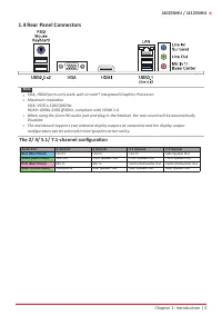
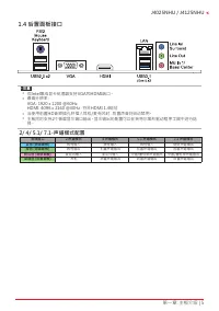
Chapter 1: Introduction | 5 J4025NHU / J4125NHU 1�4 Rear Panel Connectors Note » VGA, HDMI ports only work with an Intel® integrated Graphics Processor. » Maximum resolution VGA: 1920 x 1200 @60Hz HDMI: 4096x 2160 @30Hz, compliant with HDMI 1.4 » When using the front HD audio jack and plug in ...
Page 6 - Motherboard Layout
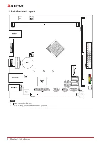
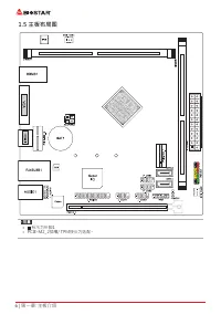
6 | Chapter 1: Introduction 1.5 Motherboard Layout Note » represents the 1st pin. » The PCIE-M2_2 slot/ TPM header is optional.
Page 7 - Chapter 2: Hardware installation; Connect Cooling Fans; may be different according to the fan manufacturer.; Install System Memory; DDR4 Modules
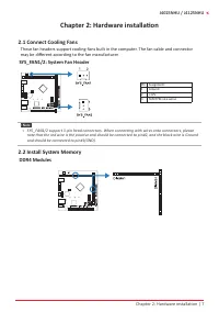
Chapter 2: Hardware installation | 7 J4025NHU / J4125NHU Chapter 2: Hardware installation 2.1 Connect Cooling Fans These fan headers support cooling-fans built in the computer. The fan cable and connector may be different according to the fan manufacturer. SYS_FAN1/2: System Fan Header Pin Assignmen...
Page 8 - Memory Capacity; DIMM Socket Location DDR4 Module; Dual Channel Memory Installation; Dual Channel Status
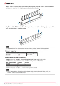
8 | Chapter 2: Hardware installation Step 1: Unlock a DIMM slot by pressing the retaining clips outward. Align a DIMM on the slot such that the notch on the DIMM matches the break on the slot. Step 2: Insert the DIMM vertically and firmly into the slot until the retaining clips snap back in place an...
Page 9 - Install an Expansion Card; You can install your expansion card by following steps:
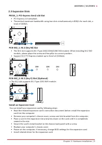
Chapter 2: Hardware installation | 9 J4025NHU / J4125NHU 2.3 Expansion Slots PEX16_1: PCI-Express Gen2 x16 Slot • PCI-Express 2.0 compliant. • Theoretical maximum bandwidth using two slots simultaneously is 8GB/s for each slot, a total of 16GB/s. PCIE-M2_1: M.2 (Key M) Slot • The M.2 slot support...
Page 10 - JCMOS1: Clear CMOS Jumper; follow the procedures to avoid damaging the motherboard.; Clear CMOS Procedures:; Load Optimal Defaults and save settings in CMOS.
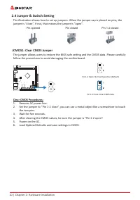
10 | Chapter 2: Hardware installation 2.4 Jumper & Switch Setting The illustration shows how to set up jumpers. When the jumper cap is placed on pins, the jumper is “close”, if not, that means the jumper is “open”. Pin opened Pin closed Pin 1-2 closed JCMOS1: Clear CMOS Jumper The jumper allows ...
Page 11 - ATXPWR1: ATX Power Source Connector; The connector provides +12V to the CPU power circuit.; PANEL1: Front Panel Header
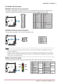
Chapter 2: Hardware installation | 11 J4025NHU / J4125NHU 2.5 Headers & Connectors ATXPWR1: ATX Power Source Connector For better compatibility, we recommend to use a standard ATX 24-pin power supply for this connector. Make sure to find the correct orientation before plugging the connector. Pin...
Page 13 - This header allows you to connector printer on the PC.
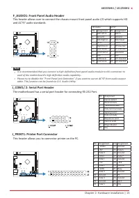
Chapter 2: Hardware installation | 13 J4025NHU / J4125NHU F_AUDIO1: Front Panel Audio Header This header allows user to connect the chassis-mount front panel audio I/O which supports HD and AC’97 audio standards. HD Audio AC’97 Pin Assignment Pin Assignment 1 Mic Left in 1 Mic In 2 Ground 2 Ground 3...
Page 14 - The BIOS can be updated using either of the following utilities:; Updating BIOS with BIOSTAR BIO-Flasher
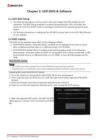
14 | Chapter 3: UEFI BIOS & Software Chapter 3: UEFI BIOS & Software 3.1 UEFI BIOS Setup • The BIOS Setup program can be used to view and change the BIOS settings for the computer. The BIOS Setup program is accessed by pressing the <DEL> key after the Power-On Self-Test (POST) memory ...
Page 15 - BIOS Update Utility (through the Internet); An open dialog will show up to request your
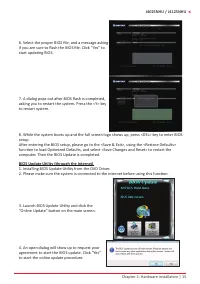
Chapter 2: Hardware installation | 15 J4025NHU / J4125NHU 6. Select the proper BIOS file, and a message asking if you are sure to flash the BIOS file. Click “Yes” to start updating BIOS. 7. A dialog pops out after BIOS flash is completed, asking you to restart the system. Press the <Y> key to ...
Page 16 - BIOS Update Utility (through a BIOS file); A warning message will show up to request your
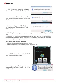
16 | Chapter 2: Hardware installation 5. If there is a new BIOS version, the utility will ask you to download it. Click “Yes” to proceed. 6. After the download is completed, you will be asked to program (update) the BIOS or not. Click “Yes” to proceed. 7. After the updating process is finished, you ...
Page 17 - Backup BIOS; for the backup of BIOS, and select a proper
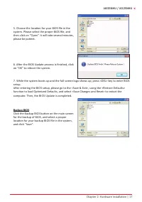
Chapter 2: Hardware installation | 17 J4025NHU / J4125NHU 5. Choose the location for your BIOS file in the system. Please select the proper BIOS file, and then click on “Open”. It will take several minutes, please be patient. 6. After the BIOS Update process is finished, click on “OK” to reboot the ...
Page 18 - Installing Software; Follow the on-screen instructions to complete the installation.; Launching Software
18 | Chapter 2: Hardware installation 3.3 Software Installing Software 1. Insert the Setup DVD to the optical drive. The driver installation program would appear if the Auto-run function has been enabled. 2. Select Software Installation, and then click on the respective software title. 3. Follow the...
Page 19 - Chapter 4: Useful help; Driver Installation; You will see the following window after you insert the DVD; A. Driver Installation; installation program.; B. Software Installation; Manual icon to browse for available manual.
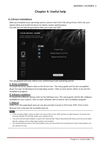
Chapter 4: Useful help | 19 J4025NHU / J4125NHU Chapter 4: Useful help 4�1 Driver Installation After you installed your operating system, please insert the Fully Setup Driver DVD into your optical drive and install the driver for better system performance. You will see the following window after you...
Page 20 - AMI BIOS Beep Code; Boot Block Beep Codes; POST BIOS Beep Codes; Number of Beeps; AMI BIOS post code; Code Description
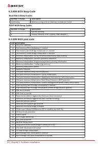
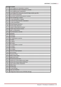
20 | Chapter 2: Hardware installation 4.2 AMI BIOS Beep Code Boot Block Beep Codes Number of Beeps Description Continuing Memory sizing error or Memory module not found POST BIOS Beep Codes Number of Beeps Description 1 Success booting. 8 Display memory error (system video adapter) 4�3 AMI BIOS post...
Page 22 - Troubleshooting; Probable; CPU Overheated; protection function has been activated.
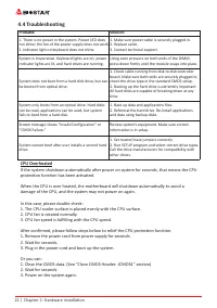
22 | Chapter 2: Hardware installation 4�4 Troubleshooting Probable Solution 1. There is no power in the system. Power LED does not shine; the fan of the power supply does not work 2. Indicator light on keyboard does not shine. 1. Make sure power cable is securely plugged in. 2. Replace cable. 3. Con...
Page 23 - Arabic
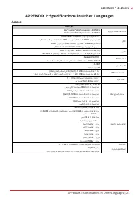
APPENDIX I: Specifications in Other Languages | 23 J4025NHU / J4125NHU APPENDIX I: Specifications in Other Languages Arabic تﺎﻔﺻاﻮﻤﻟا ﺔﻳﺰآﺮﻤﻟا ﺔﺠﻟﺎﻌﻤﻟا ةﺪﺣو ةﺪﻋﺎﻗ Intel ® Celeron ® J4025 processor : J4025NHU Intel ® Celeron ® J4125 processor : J4125NHU ةﺮآاﺬﻟا يد ﺔﺟودﺰﻣ ةﺎﻨﻗ ﻢﻋﺪﺗ . يد . را . DDR4-18...
Page 24 - German
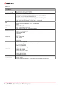
24 | APPENDIX I: Specifications in Other Languages German Spezifikationen CPU-Unterstützung J4025NHU: Intel® Celeron® J4025 processorJ4125NHU: Intel® Celeron® J4125 processor Festplattenspeicher Unterstützt Dual-Channel DDR4-1866/2133/24002x DDR4 DIMM Arbeitsspeicher-Steckplatz, Max. Unterstützt bis...
Page 25 - Russian
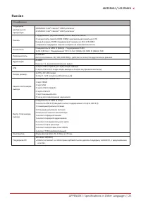
APPENDIX I: Specifications in Other Languages | 25 J4025NHU / J4125NHU Russian Спецификации Поддержка центрального процессора J4025NHU: Intel® Celeron® J4025 processorJ4125NHU: Intel® Celeron® J4125 processor Память Поддерживает двухканальный DDR4-1866/2133/24002 гнезда платы памяти DDR4 DIMM, макси...
Page 26 - Spanish
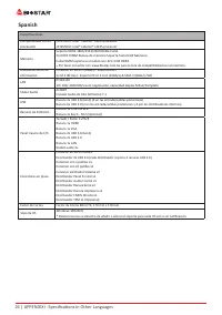
26 | APPENDIX I: Specifications in Other Languages Spanish Especificaciones Compatibilidad con el procesador J4025NHU: Intel® Celeron® J4025 processorJ4125NHU: Intel® Celeron® J4125 processor Memoria Soporta DDR4-1866/2133/2400 Doble Canal 2x DDR4 DIMM Ranura de memoria Soporta hasta 8 GB Memoria Ca...
Page 27 - Thai
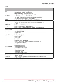
APPENDIX I: Specifications in Other Languages | 27 J4025NHU / J4125NHU Thai คุณสมบัต ซีพีย J4025NHU: Intel ® Celeron ® J4025 processor J4125NHU: Intel ® Celeron ® J4125 processor หน่วยความจำา สนับสนุน Dual Channel DDR4-1866/2133/2400รองรับหน่วยความจำา 2 สล็อต DDR4 DIMM สูงสุดถึง 8 GBทุก DIMM สนับสนุ...
Page 29 - 防静电操作规则
FCC条款 依照FCC条款第15部分的规定,本装置已经通过测试并且符合Class B级数字装置的限制。 此条款限制了在安装过程中可能造成的有害射频干扰并提供了合理的防范措施。本装置在 使用时会产生无线射频辐射,如果没有依照本手册的指示安装和使用,可能会与无线通讯 装置产生干扰。然而,并不保证在特定的安装下不会发生任何干扰。 如果关闭和重新开启本设备后,仍确定本装置造成接收广播或电视的干扰,用户可以使用 以下列表中的一种或多种方法来减少干扰: • 重新安装或调整接收天线。 • 增加本设备与接收设备之间的距离。 • 连接设备连接到不同的插座以便于两个设备使用不同的回路。 • 咨询经销商或富有经验的...
Page 30 - 目录; 第一章: 主板介绍 �������������������������������������������������������������������������������������������������������
2 | 目录 目录 第一章: 主板介绍 ������������������������������������������������������������������������������������������������������� 3 1.1 前言 ............................................................................................................................................... 3 1.2 包装清单 ...............
Page 32 - 主板特性
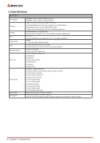
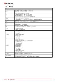
4 | 第一章: 主板介绍 1�3 主板特性 规格 CPU J4025NHU: Intel ® Celeron ® J4025 processor J4125NHU: Intel ® Celeron ® J4125 processor 内存 支持双通道DDR4-1866/2133/24002个DDR4 DIMM插槽,最大内存容量为8GB每个DIMM支持非ECC 4GB DDR4内存模组* 请访问 www.biostar.com.tw 获取内存的支持列表 存储器 2个SATA III接口 (6Gb/s):支持 AHCI1个M.2 (M Key) : 支持 PCI-E 2.0 x2 (10Gb/s...
Page 35 - 此风扇接头支持电脑内置的冷却风扇,风扇引线和插头可能因制造商而异。; DDR4 内存模组
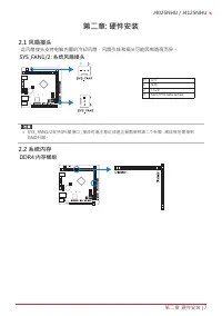
第二章: 硬件安装 | 7 J4025NHU / J4125NHU 第二章: 硬件安装 2�1 风扇接头 此风扇接头支持电脑内置的冷却风扇,风扇引线和插头可能因制造商而异。 SYS_FAN1/2: 系统风扇接头 针 定义1 接地 2 +12V 3 FAN RPM rate sense » SYS_FAN1/2支持3针脚接口;接线时请注意红线是正极需接到第二个针脚,黑线接地需接到 GND针脚。 2�2 系统内存 DDR4 内存模组
Page 36 - 内存容量; DIMM插槽位置; 双通道内存安装; 为激活主板双通道功能,使用内存模组必须符合以下要求: 成对安装相同密度的内存模; 双通道状态
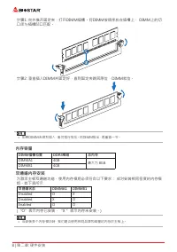
8 | 第二章: 硬件安装 步骤1: 向外推开固定夹,打开DIMM插槽。将DIMM按顺序放在插槽上, DIMM上的切 口须与插槽凹口匹配。 步骤2: 垂直插入DIMM并固定好,直到固定夹跳回原位,DIMM就位。 » 如果DIMM未顺利插入,请勿强行按压。将DIMM拔出,再重插一次。 内存容量 DIMM插槽位置 DDR4模组 总内存 DIMMA1 4GB 最大为 8GB. DIMMB1 4GB 双通道内存安装 为激活主板双通道功能,使用内存模组必须符合以下要求: 成对安装相同密度的内存模 组。如下表所示 双通道状态 DIMMA1 DIMMB1 Disabled O X Disabled X O ...
Page 37 - 安装扩展卡
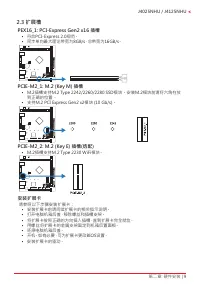
第二章: 硬件安装 | 9 J4025NHU / J4125NHU 2�3 扩展槽 PEX16_1: PCI-Express Gen2 x16 插槽 • 符合PCI-Express 2.0规范。 • 同步单向最大理论带宽为8GB/s,总带宽为16GB/s。 PCIE-M2_1: M�2 (Key M) 插槽 • M.2插槽支持M.2 Type 2242/2260/2280 SSD模块。安装M.2模块前请将六角柱放 到正确的位置。 • 支持M.2 PCI Express Gen2 x2模块 (10 Gb/s)。 PCIE-M2_2: M�2 (Key E) 插槽(选配) • M.2插槽支持M.2...
Page 38 - 下图展示如何设置跳线。当跳帽放置在针脚上时,跳线为闭合(close)状态。否则跳线为; 打开; 闭合
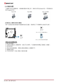
10 | 第二章: 硬件安装 2�4 跳线设置 下图展示如何设置跳线。当跳帽放置在针脚上时,跳线为闭合(close)状态。否则跳线为 断开(open)状态。 Pin 打开 Pin 闭合 Pin 1-2 闭合 JCMOS1: 清空CMOS 跳线 用户可清空CMOS数据并恢复BIOS安全设置,请按照以下步骤操作以免损坏主板。 Pin 1-2 打开: 正常操作(默认) Pin 1-2 闭合: 清空CMOS数据 清空CMOS数据过程: 1. 断开AC电源。 2. 将跳线设置成1-2接脚闭合,建议可以使用一个金属物体如螺丝刀触碰1-2接脚。 3. 等待5秒钟。 4. 清空CMOS数据後,请确认跳线设置成...
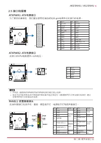
Page 39 - 为了更好的兼容性,我们建议使用标准的ATX24-pin电源供应此接口的电源。; 此16针脚接口包含开机,重启,硬盘指示灯,电源指示灯和扬声器接口。
第二章: 硬件安装 | 11 J4025NHU / J4125NHU 2�5 接口和插槽 ATXPWR1: ATX电源接口 为了更好的兼容性,我们建议使用标准的ATX24-pin电源供应此接口的电源。 针 定义 针 定义 13 +3.3V 1 +3.3V 14 -12V 2 +3.3V 15 接地 3 接地 16 PS_ON 4 +5V 17 接地 5 接地 18 接地 6 +5V 19 接地 7 接地 20 NC 8 PW_OK 21 +5V 9 唤醒电压+5V 22 +5V 10 +12V 23 +5V 11 +12V 24 接地 12 +3.3V ATXPWR2: ATX电源接口 此接口...
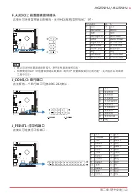
Page 41 - 此主板有一个串行端口可接出RS-232接头。
第二章: 硬件安装 | 13 J4025NHU / J4125NHU F_AUDIO1: 前置面板音频接头 此接头可连接音频输出数据线,支持HD(高清)音频和AC’97。 HD Audio AC’97 针 定义 针 定义 1 Mic Left in 1 Mic In 2 接地 2 接地 3 Mic Right in 3 Mic Power 4 GPIO 4 Audio Power 5 Right line in 5 RT Line Out 6 Jack Sense 6 RT Line Out 7 Front Sense 7 Reserved 8 Key 8 Key 9 Left line in...
Page 42 - �1 UEFI BIOS设置
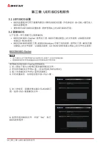
14 | 第三章: UEFI BIOS和软件 第三章: UEFI BIOS和软件 3�1 UEFI BIOS设置 • BIOS设置程序可用于查看和更改计算机的BIOS设置。开机自检时,按<DEL>键可进入 BIOS设置程序。 • 更多相关UEFI BIOS设置信息,请参考网站上的UEFI BIOS手册。 3�2 刷新BIOS 以下任意一种工具都可以刷新BIOS: • BIOSTAR BIO-Flasher: 使用此工具,BIOS可通过硬盘上的文件刷新,USB驱动刷新, 或者CD-ROM 刷新。 • BIOSTAR BIOS刷新工具: 能够在Windows 环境下自动刷新。使用此工具...
Page 43 - BIOS刷新工具(通过网络)
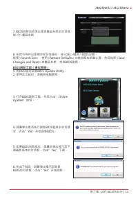
第三章: UEFI BIOS和软件 | 15 J4025NHU / J4125NHU 7. BIOS刷新后会弹出是否重启系统的对话框。 按<Y>重启系统 8. 系统引导并出现相关标识信息时,按<DEL>键进入BIOS设置。 选择<Save & Exit>,使用<Restore Defaults>功能加载系统默认值,然后选择<Save Changes and Reset>来重启系统,完成BIOS刷新。 BIOS刷新工具(通过网络) 1. 用DVD驱动安装BIOS Update Utility。 2. 使用此功能时,请确保电脑联网...
Page 44 - BIOS刷新工具(通过BIOS文件)
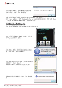
16 | 第三章: UEFI BIOS和软件 7. 刷新程序结束后,屏幕弹出提示您重启系 统的对话框。点击”OK”重启系统。 8. 系统引导并出现相关标识信息时,按<DEL>键进入BIOS设置。 选择<Save & Exit>,使用<Restore Defaults>功能加载系统默认值,然后选择<Save Changes and Reset>来重启系统,完成BIOS刷新。 BIOS刷新工具(通过BIOS文件) 1. 用DVD驱动安装BIOS刷新工具。 2. 从我们的网站www.biostar.com.tw 下载合适的BIOS. 3. 在主...
Page 45 - Changes and Reset>来重启系统,完成BIOS刷新。; BIOS备份; 点击BIOS备份按钮,选择存储备份文件的合适
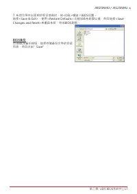
第三章: UEFI BIOS和软件 | 17 J4025NHU / J4125NHU 7. 系统引导并出现相关标识信息时,按<DEL>键进入BIOS设置。 选择<Save & Exit>,使用<Restore Defaults>功能加载系统默认值,然后选择<Save Changes and Reset>来重启系统,完成BIOS刷新。 BIOS备份 点击BIOS备份按钮,选择存储备份文件的合适 目录,然后点击”Save”。
Page 46 - 安装软件; 将光盘放入光驱,若Autorun功能已激活,驱动安装程序将会出现。; 启动软件; 安装程序完成后,桌面上将出现软件图标。请双击图标启动软件工具。
18 | 第三章: UEFI BIOS和软件 3�3 软件 安装软件 1. 将光盘放入光驱,若Autorun功能已激活,驱动安装程序将会出现。 2. 选择Software Installation,然后点击各软件图标。 3. 根据屏幕上的指令完成安装。 启动软件 安装程序完成后,桌面上将出现软件图标。请双击图标启动软件工具。 » 所有软件的相关信息和内容若有变更,恕不另行通知。为使系统性能更佳,软件会不断升级。 » 下面的图片和信息仅供参考,此主板的实际信息和设置可能与手册稍有差异。
Page 47 - 驱动程序安装注意事项; A� 驱动程序安装
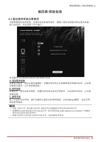
第四章:帮助信息 | 19 J4025NHU / J4125NHU 第四章:帮助信息 4�1 驱动程序安装注意事项 为获得更好的系统性能,在操作系统安装完成后,请插入您的系统驱动到光驱并安装。 插入DVD后,将出现如下所示窗口。 此设置向导将自动检测您的主板和操作系统。 A� 驱动程序安装 安装驱动程序,请点击驱动器图标。设置向导将列出主板兼容驱动和操作系统。点击各 设备驱动程序,以开始安装进程。 B� 软件安装 安装软件,请点击软件图标。设置向导将列出系统可用软件,点击各软件名称,以开始 安装进程。 C� 使用手册 除了书本形式的手册,我们也提供光盘形式的使用指南。点击Manual图标,浏览...
Page 48 - AMI BIOS 哔声代码; 引导模块哔声代码; BIOS 开机自检哔声代码; 哔声次数; AMI BIOS 开机自检代码; 代码 含义
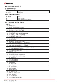
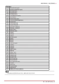
20 | 第二章: 硬件安装 4�2 AMI BIOS 哔声代码 引导模块哔声代码 哔声次数 含义 持续哔声 持续哔声 BIOS 开机自检哔声代码 哔声次数 含义 1 系统引导成功 8 显存错误(系统视频适配器) 4�3 AMI BIOS 开机自检代码 代码 含义 10 PEI核心启动11 CPU Pre-memory初始化启动15 北桥Pre-memory初始化启动19 南桥Pre-memory初始化启动2B 内存初始化,读取SPD数据 2C 内存初始化,检测Memory presence 2D 内存初始化,编程内存时序信息 2E 内存初始化,配置内存2F 内存初始化(其他)31 内存安装完...
Page 50 - 问题解答; 问题
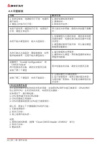
22 | 第二章: 硬件安装 4�4 问题解答 问题 解决方法 1. 系统没有电,电源指示灯不亮,电源风 扇不转动。 2. 键盘上的指示灯不亮。 1. 确定电源线是否接好。 2. 更换线材。 3. 联系技术支持。 系统不起作用。键盘指示灯亮,电源指示 灯亮,硬盘正常运作。 用力按压内存两端,确保内存安置于插槽 中。 系统不能从硬盘启动,能从光盘启动。 1. 检查硬盘与主板的连线,确定各连线是 否确实接好,检查标准CMOS设置中的驱 动类型。 2. 硬盘随时都有可能坏掉,所以备份硬盘 数据是很重要的。 系统只能从光盘启动。硬盘能被读,应用 程序能被使用,但是不能从硬盘启动。 1. 备份数据和应用...
Page 51 - 附录I:产品中有毒有害物质或元素的名称及含量 | 23; 附录I:产品中有毒有害物质或元素的名称及含量
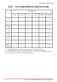
附录I:产品中有毒有害物质或元素的名称及含量 | 23 J4025NHU / J4125NHU 附录I:产品中有毒有害物质或元素的名称及含量 部件名称 有毒有害物质或元素 铅 (Pb) 汞 (Hg) 镉 (Cd) 六价铬 (Cr(VI)) 多溴联苯 (PBB) 多溴二苯醚 (PBDE) PCB板 O O O O O O 结构件 O O O O O O 芯片及其它 主动零件 X O O O O O 连接器 X O O O O O 被动电子元 器件 X O O O O O 焊接金属 O O O O O O 线材 O O O O O O 助焊剂,散 热 膏,标签 及其它耗材 O O O O O O ...


 Biostar A68N-2100K
User Manual
Biostar A68N-2100K
User Manual
 Biostar B450NH
User Manual
Biostar B450NH
User Manual
 Biostar B550
User Manual
Biostar B550
User Manual
 Biostar B550MH
User Manual
Biostar B550MH
User Manual
 Biostar B550MX/E PRO
User Manual
Biostar B550MX/E PRO
User Manual
 Biostar B550T
User Manual
Biostar B550T
User Manual
 Biostar B560MH-E 2.0
User Manual
Biostar B560MH-E 2.0
User Manual
 Biostar B660GTA
User Manual
Biostar B660GTA
User Manual
 Biostar B660GTQ
User Manual
Biostar B660GTQ
User Manual
 Biostar B660MX-E PRO
User Manual
Biostar B660MX-E PRO
User Manual
 Biostar B760
User Manual
Biostar B760
User Manual
 Biostar H510
User Manual
Biostar H510
User Manual
 Biostar H610
User Manual
Biostar H610
User Manual
 Biostar H61MHV3
User Manual
Biostar H61MHV3
User Manual
 Biostar H81MHV3 3.0
User Manual
Biostar H81MHV3 3.0
User Manual
 Biostar Z490
User Manual
Biostar Z490
User Manual