Page 2 - | Table Of Contents; Table Of Contents; FCC Information and Copyright; Motherboard Layout; Chapter 2: Hardware installation; Driver Installation; APPENDIX I: Specifications in Other Languages
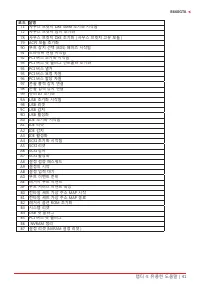
2 | Table Of Contents Table Of Contents FCC Information and Copyright ������������������������������������������������������������������������������� 1 Chapter 1: Introduction ������������������������������������������������������������������������������������������� 3 1.1 Before You Start ............
Page 3 - Chapter 1: Introduction; Before You Start; sure you follow the instructions below:; Package Checklist; • Serial ATA Cable x4
Chapter 1: Introduction | 3 B660GTA Chapter 1: Introduction 1�1 Before You Start Thank you for choosing our product. Before you start installing the motherboard, please make sure you follow the instructions below: • Prepare a dry and stable working environment with sufficient lighting. • Always di...
Page 6 - Rear Panel Connectors
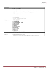
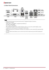
6 | Chapter 1: Introduction 1.4 Rear Panel Connectors Note » HDMI/ DP/ DVI-D ports only work with an Intel® integrated Graphics Processor. » Maximum resolution HDMI: 4096 x 2160 @60Hz, compliant with HDMI 2.0 DP: 4096 x 2304 @60Hz DVI-D: 1920 x 1200 @60Hz » The mainboard supports three onboard...
Page 8 - Step 1: Locate the CPU socket on the motherboard; Step 2: Open ILM Lever and then load plate using finger tab.
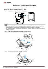
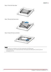
8 | Chapter 2: Hardware installation Chapter 2: Hardware installation 2.1 Install Central Processing Unit (CPU) Step 1: Locate the CPU socket on the motherboard Note » Remove pin cap before installation, and make good preservation for future use. When the CPU is removed, cover the pin cap on the e...
Page 10 - Install a Heatsink; to the CPU fan connector.
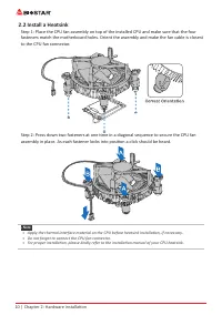
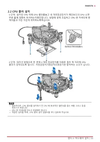
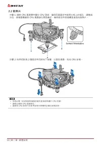
10 | Chapter 2: Hardware installation 2.2 Install a Heatsink Step 1: Place the CPU fan assembly on top of the installed CPU and make sure that the four fasteners match the motherboard holes. Orient the assembly and make the fan cable is closest to the CPU fan connector. Step 2: Press down two fasten...
Page 11 - Connect Cooling Fans; may be different according to the fan manufacturer.
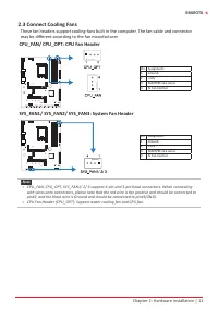
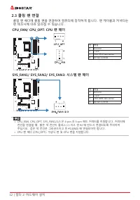
Chapter 2: Hardware installation | 11 B660GTA 2.3 Connect Cooling Fans These fan headers support cooling-fans built in the computer. The fan cable and connector may be different according to the fan manufacturer. CPU_FAN/ CPU_OPT: CPU Fan Header Pin Assignment1 Ground 2 +12V 3 FAN RPM rate sense 4 A...
Page 12 - Install System Memory; DDR4 Modules; such that the notch on the DIMM matches the break on the slot.
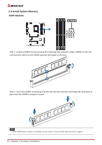
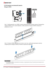
12 | Chapter 2: Hardware installation 2.4 Install System Memory DDR4 Modules Step 1: Unlock a DIMM slot by pressing the retaining clips outward. Align a DIMM on the slot such that the notch on the DIMM matches the break on the slot. Step 2: Insert the DIMM vertically and firmly into the slot until t...
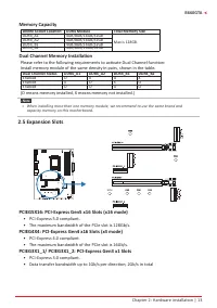
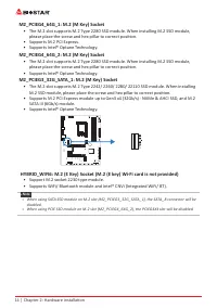
Page 13 - Memory Capacity; DIMM Socket Location DDR4 Module; Dual Channel Memory Installation; Dual Channel Status; • The maximum bandwidth of the PCIe slot is 128Gb/s.
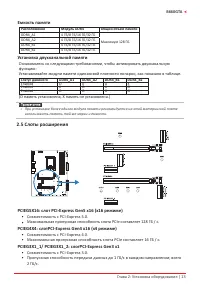
Chapter 2: Hardware installation | 13 B660GTA Memory Capacity DIMM Socket Location DDR4 Module Total Memory Size DDR4_A1 4GB/8GB/16GB/32GB Max is 128GB. DDR4_A2 4GB/8GB/16GB/32GB DDR4_B1 4GB/8GB/16GB/32GB DDR4_B2 4GB/8GB/16GB/32GB Dual Channel Memory Installation Please refer to the following requir...
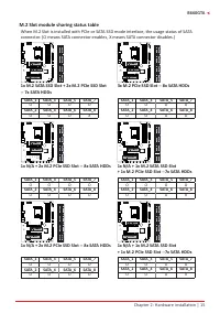
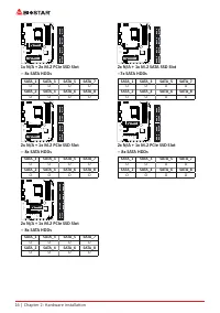
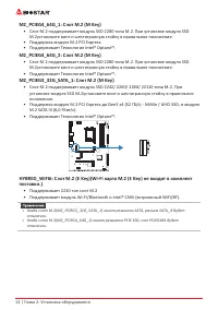
Page 15 - M.2 Slot module sharing status table
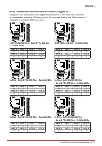
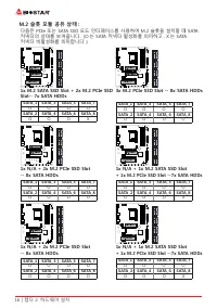
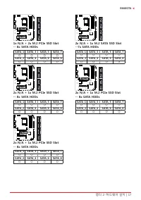
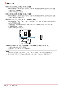
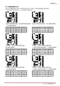
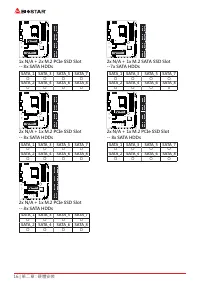
Chapter 2: Hardware installation | 15 B660GTA M.2 Slot module sharing status table When M.2 Slot is installed with PCIe or SATA SSD mode interface, the usage status of SATA connector. (O means SATA connector enables, X means SATA connector disables.) 1x M.2 SATA SSD Slot + 2x M.2 PCIe SSD Slot-- 7x ...
Page 17 - Install an Expansion Card
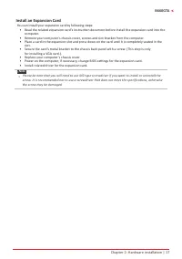
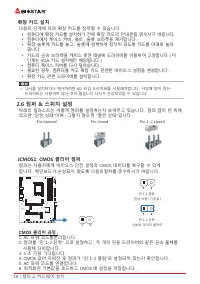
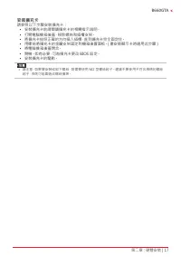
Chapter 2: Hardware installation | 17 B660GTA Install an Expansion Card You can install your expansion card by following steps: • Read the related expansion card’s instruction document before install the expansion card into the computer. • Remove your computer’s chassis cover, screws and slot brac...
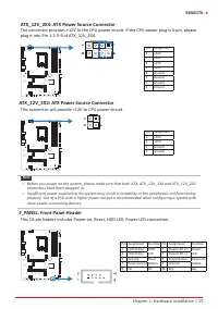
Page 18 - JCMOS1: Clear CMOS Jumper; follow the procedures to avoid damaging the motherboard.; Clear CMOS Procedures:; Load Optimal Defaults and save settings in CMOS.; ATX: ATX Power Source Connector
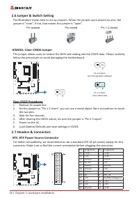
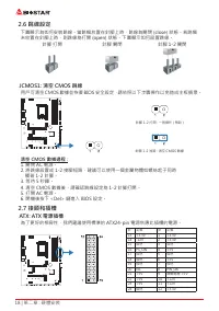
18 | Chapter 2: Hardware installation 2.6 Jumper & Switch Setting The illustration shows how to set up jumpers. When the jumper cap is placed on pins, the jumper is “close”, if not, that means the jumper is “open”. Pin opened Pin closed Pin 1-2 closed JCMOS1: Clear CMOS Jumper The jumper allows ...
Page 20 - SPKR: Chassis Speaker Header; Please connect the chassis speaker to this header.; These connectors connect to SATA hard disk drives via SATA cables.
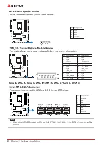
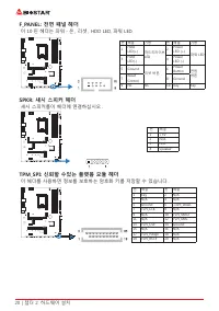
20 | Chapter 2: Hardware installation SPKR: Chassis Speaker Header Please connect the chassis speaker to this header. Pin Assignment1 +5V 2 N/A 3 N/A 4 Speaker TPM_SPI: Trusted Platform Module Header This header allows you to store cryptographic keys that protect information. Pin Assignment Pin Assi...
Page 22 - THUNDERBOLT: Thunderbolt Header; can be connected with a wide range of external peripherals.; COM1: Serial Port Header
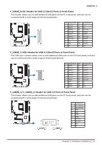
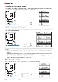
22 | Chapter 2: Hardware installation THUNDERBOLT: Thunderbolt Header This header allows user to add additional Thunderbolt ports on the PC front panel, and also can be connected with a wide range of external peripherals. Pin Assignment1 Force Power 2 Key 3 CIO Plug Event 4 SMB_DATA_MAIN 5 SLP_S3_N ...
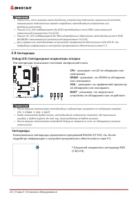
Page 24 - Debug LED: Debug LED Indicators; This LEDs indicate the status of the motherboard.; CPU; - indicates CPU is not detected or fail.; DRAM; - indicates DRAM is not detected or fail.; VGA; - indicates GPU is not detected or fail.; BOOT; - indicates booting device is not detected; LEDs; detail software setting.
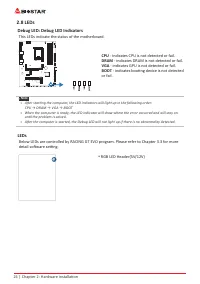
24 | Chapter 2: Hardware installation 2.8 LEDs Debug LED: Debug LED Indicators This LEDs indicate the status of the motherboard. CPU - indicates CPU is not detected or fail. DRAM - indicates DRAM is not detected or fail. VGA - indicates GPU is not detected or fail. BOOT - indicates booting device is...
Page 25 - The BIOS can be updated using either of the following utilities:; Updating BIOS with BIOSTAR BIO-Flasher
Chapter 3: UEFI BIOS & Software | 25 B660GTA Chapter 3: UEFI BIOS & Software 3.1 UEFI BIOS Setup • The BIOS Setup program can be used to view and change the BIOS settings for the computer. The BIOS Setup program is accessed by pressing the <DEL> key after the Power-On Self-Test (POST)...
Page 26 - BIOS Update Utility (through the Internet); An open dialog will show up to request your
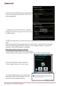
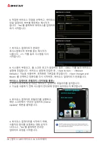
26 | Chapter 3: UEFI BIOS & Software 6. Select the proper BIOS file, and a message asking if you are sure to flash the BIOS file. Click “Yes” to start updating BIOS. 7. A dialog pops out after BIOS flash is completed, asking you to restart the system. Press the <Y> key to restart system. 8...
Page 27 - BIOS Update Utility (through a BIOS file); A warning message will show up to request your
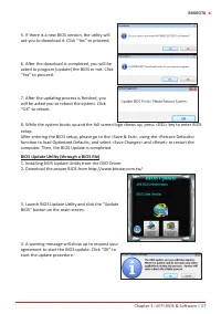
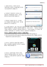
Chapter 3: UEFI BIOS & Software | 27 B660GTA 5. If there is a new BIOS version, the utility will ask you to download it. Click “Yes” to proceed. 6. After the download is completed, you will be asked to program (update) the BIOS or not. Click “Yes” to proceed. 7. After the updating process is fin...
Page 28 - then click on “Open”. It will take several minutes,; Backup BIOS; for the backup of BIOS, and select a proper
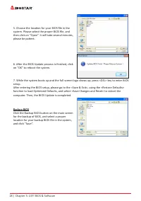
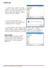
28 | Chapter 3: UEFI BIOS & Software 5. Choose the location for your BIOS file in the system. Please select the proper BIOS file, and then click on “Open”. It will take several minutes, please be patient. 6. After the BIOS Update process is finished, click on “OK” to reboot the system. 7. While ...
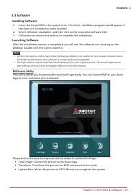
Page 29 - Installing Software; Follow the on-screen instructions to complete the installation.; Launching Software; BIOScreen Utility; logo so as to customize your computer.
Chapter 3: UEFI BIOS & Software | 29 B660GTA 3.3 Software Installing Software 1. Insert the Setup DVD to the optical drive. The driver installation program would appear if the Auto-run function has been enabled. 2. Select Software Installation, and then click on the respective software title. 3....
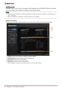
Page 30 - RACING GT EVO; System Information; Shows core speed, multiplier and bus speed.
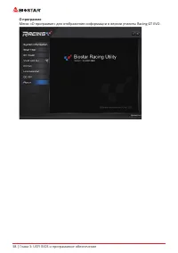
30 | Chapter 3: UEFI BIOS & Software RACING GT EVO RACING GT EVO is an easy-to-use program that integrates several BIOSTAR utilities and allows users to configure these utilities simultaneously and seamlessly. Note » Menu contents of RACING GT EVO will be different slightly, depending on diffe...
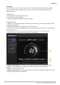
Page 31 - SmartEAR; A chassis with front audio output jacks
Chapter 3: UEFI BIOS & Software | 31 B660GTA SmartEAR Smart EAR allows you to control system volume and adjust impedance setting (Low/High Gain) to optimize your headphone performance. You can easily enjoy high-quality and awesome sound. Requirements: 1. A chassis with front audio output jacks 2...
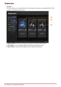
Page 32 - GT Touch; program in Windows environment.
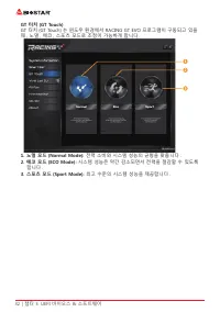
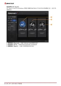
32 | Chapter 3: UEFI BIOS & Software GT Touch GT Touch allows you to adjust Normal, ECO and Sport mode when running RACING GT EVO program in Windows environment. 1. Normal Mode: It balances energy consumption and system performance. 2. ECO Mode: It saves energy by slightly reducing system perfor...
Page 33 - Vivid LED DJ
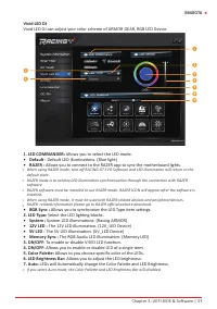
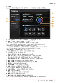
Chapter 3: UEFI BIOS & Software | 33 B660GTA Vivid LED DJ Vivid LED DJ can adjust your color scheme of ARMOR GEAR, RGB LED Device. 1. LED COMMANDER: Allows you to select the LED mode. • Default : Default LED illuminations. (Blue light) • RAZER : Allows you to connect to the RAZER app to sync t...
Page 35 - A�I Fan; Restore defaults your changes value of a single item.; Allows you to control mode of the fans.
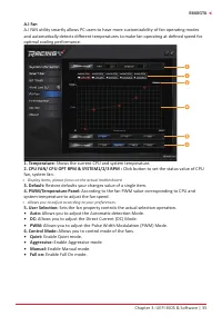
Chapter 3: UEFI BIOS & Software | 35 B660GTA A�I Fan A.I FAN utility smartly allows PC users to have more customizability of fan operating modes and automatically detects different temperatures to make fan operating at defined speed for optimal cooling performance. 1. Temperature: Shows the curr...
Page 38 - About
38 | Chapter 3: UEFI BIOS & Software About The About menu to display the Racing GT EVO Utility version information.
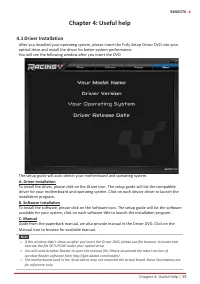
Page 39 - Chapter 4: Useful help; Driver Installation; You will see the following window after you insert the DVD; A. Driver Installation; installation program.; B. Software Installation; Manual icon to browse for available manual.
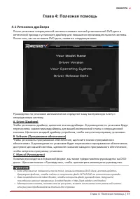
Chapter 4: Useful help | 39 B660GTA Chapter 4: Useful help 4.1 Driver Installation After you installed your operating system, please insert the Fully Setup Driver DVD into your optical drive and install the driver for better system performance. You will see the following window after you insert the ...
Page 40 - AMI BIOS Beep Code; Boot Block Beep Codes; POST BIOS Beep Codes; Number of Beeps; AMI BIOS post code; Code Description
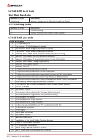
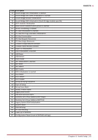
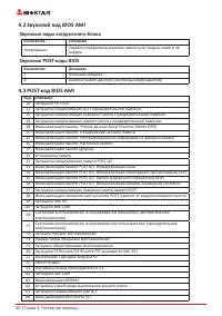
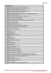
40 | Chapter 4: Useful help 4.2 AMI BIOS Beep Code Boot Block Beep Codes Number of Beeps Description Continuing Memory sizing error or Memory module not found POST BIOS Beep Codes Number of Beeps Description 1 Success booting. 8 Display memory error (system video adapter) 4.3 AMI BIOS post code Code...
Page 42 - Troubleshooting; Probable; CPU Overheated; protection function has been activated.
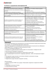
42 | Chapter 4: Useful help 4.4 Troubleshooting Probable Solution 1. There is no power in the system. Power LED does not shine; the fan of the power supply does not work 2. Indicator light on keyboard does not shine. 1. Make sure power cable is securely plugged in. 2. Replace cable. 3. Contact techn...
Page 43 - RAID Functions; RAID Definitions; written across all the drives in the array. By using multiple; Data are stored twice by writing them to both the data disk; Features and Benefits
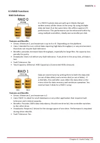
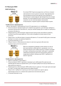
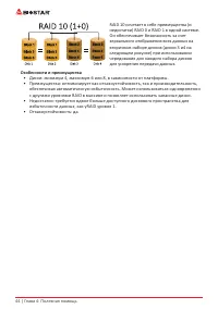
Chapter 4: Useful help | 43 B660GTA 4.5 RAID Functions RAID Definitions In a RAID 0 system data are split up in blocks that get written across all the drives in the array. By using multiple disks (at least 2) at the same time, this offers superior I/O performance. This performance can be enhanced fu...
Page 45 - Intel® OptaneTM Technology (powered by 3D XPoint memory); Optane technology has the potential to; Features and Benefits :; Massive in-memory data base; Reqirement for Intel® Optane Introduction :; Intel® Optane Memory or Storage.
Chapter 4: Useful help | 45 B660GTA 4.6 Intel® Optane™ Technology (powered by 3D XPoint memory) With Intel® Optane™ technology you can unleash the power of your processor instead of it working at a fraction of its power. Eliminating that bottleneck requires better storage memory that is fast, inexpe...
Page 46 - Arabic
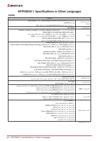
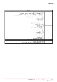
46 | APPENDIX I: Specifications in Other Languages 46 | APPENDIX l: Specifications in Other Languages APPENDIX I: Specifications in Other Languages Arabic تﺎﻔﺻاﻮﻤﻟا ﺔﺠﻟﺎﻌﻤﻟا ةﺪﺣو ةﺪﻋﺎﻗ ﺔﻳﺰآﺮﻤﻟا Intel ® Celeron تﺎﺠﻟﺎﻌﻣ / Intel ® Pentium 12 Intel ® Core™ i9/ i7/ i5/ i3 تﺎﺠﻟﺎﻌﻣ ﻢﻋد LGA1700 ﺔﻣﺰﺣ ﻲﻓ * ﻊﻗ...
Page 48 - German
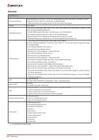
48 | German German Spezifikationen CPU-Unterstützung Unterstützung für Intel® Core ™ i9/ i7/ i5/ i3-Prozessoren der 12th. Generation und Intel® Pentium®-Prozessoren/ Intel® Celeron®-Prozessoren im LGA1700-Paket* Bitte konsultieren Sie www.biostar.com.tw für CPU-Unterstützungsliste Chipset Intel® B66...
Page 49 - APPENDIX l: Specifications in Other Languages | 49
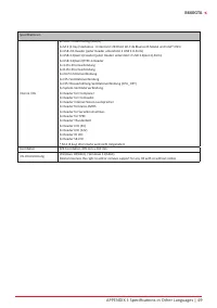
German | 49 B660GTA Spezifikationen Interne I/Os 8x SATA III-Verbindung (6Gb/s)1x M.2 (E Key) Steckdose : Unterstützt 2230 Art Wi-Fi & Bluetooth Modul und Intel® CNVi 2x USB 2.0-Header (jeder Header unterstützt 2 USB 2.0-Ports)1x USB 3.2(Gen1)-Header (jeder Header unterstützt 2 USB 3.2(Gen1)-Por...
Page 50 - Spanish; 0 | APPENDIX l: Specifications in Other Languages
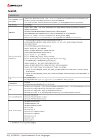
50 | German Spanish Especificaciones Compatibilidad con el procesador Soporta para procesadores Intel® Core ™ i9/ i7/ i5/ i3 de décima / 12.a generación y procesadores Intel® Pentium®/ procesadores Intel® Celeron® en el paquete LGA1700* Por favor consultar con www.biostar.com.tw para la lista de com...
Page 51 - APPENDIX l: Specifications in Other Languages | 51
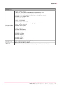
German | 51 B660GTA Especificaciones Conectores en placa Conector 8x SATA III (6Gb/s)1x M.2 (E Key) : Soporta 2230 tipo Wi-Fi & Bluetooth module and Intel® CNViDistribuidor 2x USB 2.0 (cada distribuidor soporta 2 ranuras USB 2.0)Distribuidor 1x USB 3.2(Gen1) (cada distribuidor soporta 2 ranuras ...
Page 52 - Thai; 2 | APPENDIX l: Specifications in Other Languages
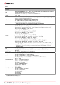
52 | German Thai คุณสมบัติ ซีพียู สนับสนุนโปรเซสเซอร์Intel ® Core™ i9/ i7/ i5/ i3 เจนเนอเรชั่น 12 และโปรเซสเซอร์Intel ® Pentium ® / โปรเซสเซอร์Intel ® Celeron ® ในแพ็คเกจ LGA1700 * เข้าชมได้ที่ www.biostar.com.tw สำาหรับรายการซีพียูที่สนับสนุน ชิพเซ็ต Intel ® B660 หน่วยความจำา สนับสนุน Dual Channel ...
Page 53 - APPENDIX l: Specifications in Other Languages | 53
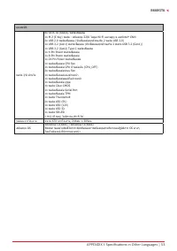
German | 53 B660GTA คุณสมบัติ พอร์ต I/O ด้านใน 8x SATA III (6Gb/s) พอร์ตเชื่อมต่อ1x M.2 (E Key) พอร์ต : สนับสนุน 2230 โมดูล Wi-Fi และบลูทู ธ และIntel ® CNVi 2x USB 2.0 พอร์ตเชื่อมต่อ (หัวเชื่อมต่อทุกตัวรองรับ 2 พอร์ต USB 2.0)1x USB 3.2 (Gen1) พอร์ตเชื่อมต่อ (หัวเชื่อมต่อทุกตัวรองรับ 2 พอร์ต USB 3.2 ...
Page 54 - Japan; 4 | APPENDIX l: Specifications in Other Languages
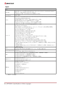
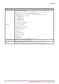
54 | German Japan 仕様 CPU 対応 LGA1700 パッケージでの第 12 世代 Intel ® Core ™ i9/ i7/ i5/ i3 プロセッサーおよび Intel ® Pentium ® プ ロセッサー / Intel ® Celeron ® プロセッサーのサポート * 対応 CPU の一覧は、www.biostar.com.tw を参照してください チップセット Intel ® B660 メモリ デュアルチャンネル DDR4-1866/ 2133/ 2400/ 2666/2800/2933/3200/3600(OC)/3800(OC)/4000(OC)/4133...
Page 55 - APPENDIX l: Specifications in Other Languages | 55
German | 55 B660GTA 仕様 内部 I/O 8x SATA III コネクタ (6Gb/s)1x M.2 (E Key) コネクタ:2230 タイプ Wi-Fi & Bluetooth モジュールと Intel ® CNVi に対応 2x USB 2.0 ヘッダー ( 各ヘッダーは 2 台の USB 2.0 ポートに対応 )1x USB 3.2 (Gen1) ヘッダー ( 各ヘッダーは 2 台の USB 3.2 (Gen1) ポートに対応 )1x USB 3.2 (Gen2) Type-C ヘッダー1x 4 ピン電源コネクタ1x 8 ピン電源コネクタ1x 24 ピン電源...
Page 57 - Информация FCC и авторское право; без обязательства заранее уведомлять какую-либо сторону.
Информация FCC и авторское право Это оборудование было протестировано и признано соответствующим ограничениям для цифровых устройств класса B в соответствии с частью 15 правил Федеральной комиссии по связи США (FCC). Эти ограничения разработаны для обеспечения разумной защиты от вредных помех при ус...
Page 58 - Содержание; Информация FCC и авторское право ��������������������������������������������������������������������
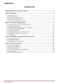
2 | Содержание Содержание Информация FCC и авторское право �������������������������������������������������������������������� 1 Глава 1: Введение �������������������������������������������������������������������������������������������������� 3 1.1 Перед началом ....................................
Page 60 - Технические характеристики
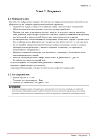
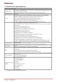
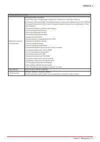
4 | Глава 1: Введение 1�3 Технические характеристики Технические характеристики Поддержка ЦП Поддержка процессоров Intel® Core ™ i9/ i7/ i5/ i3 12-го поколений и процессоров Intel® Pentium®/ Intel® Celeron® в корпусе LGA1700* Перечень поддержки центрального процессора смотрите на www.biostar.com.tw ...
Page 62 - Разъемы задней панели
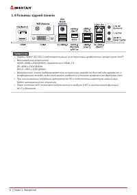
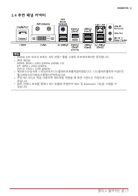
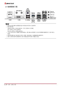
6 | Глава 1: Введение 1�4 Разъемы задней панели » » Порты HDMI/ DP/ DVI-D работают только со встроенным графическим процессором Intel®. » » Максимальное разрешение HDMI: 4096 x 2160 @60Hz, совместимо с HDMI 2.0 DP: 4096 x 2304 @60Hz DVI-D: 1920 x 1200 @60Hz » » Материнская плата поддерживает ...
Page 63 - �5 Компоновка материнской платы
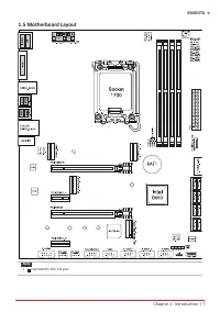
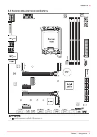
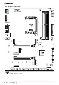
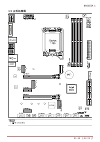
Глава 1: Введение | 7 B660GTA 1�5 Компоновка материнской платы » » представляет собой 1-й контакт.
Page 64 - Глава 2: Установка оборудования; �1 Установка центрального процессора (ЦП); Шаг 1: Найдите сокет ЦП на материнской плате.; пластину с помощью пальца.
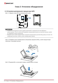
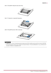
8 | Глава 2: Установка оборудования Глава 2: Установка оборудования 2�1 Установка центрального процессора (ЦП) Шаг 1: Найдите сокет ЦП на материнской плате. » » Снимите штырьковый цоколь перед установкой и сохраните его для будущего использования. После снятия ЦП накройте штырьковый цоколь на пуст...
Page 66 - �2 Установка радиатора; к разъему вентилятора ЦП.
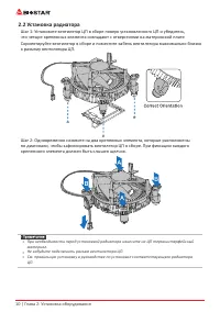
10 | Глава 2: Установка оборудования 2�2 Установка радиатора Шаг 1: Установите вентилятор ЦП в сборе поверх установленного ЦП и убедитесь, что четыре крепежных элемента совпадают с отверстиями на материнской плате. Сориентируйте вентилятор в сборе и поместите кабель вентилятора максимально близко к ...
Page 67 - �3 Подключение охлаждающих вентиляторов; от производителя вентилятора.
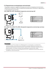
Глава 2: Установка оборудования | 11 B660GTA 2�3 Подключение охлаждающих вентиляторов Следующие штыревые соединители предназначены для охлаждающих вентиляторов, встроенных в компьютер. Кабель и разъем вентилятора могут отличаться в зависимости от производителя вентилятора. CPU_FAN/ CPU_OPT: Штыревой...
Page 68 - �4 Установка системной памяти; Модули DDR4; защелкнулисьи модуль DIMM установился должным образом.
12 | Глава 2: Установка оборудования 2�4 Установка системной памяти Модули DDR4 Шаг 1: Разблокируйте слот DIMM, нажав на фиксирующие зажимы наружу. Выровняйте модуль DIMM в слоте таким образом, чтобы выемка на модуле DIMM совпадала с разрывом в слоте. Шаг 2: Вставьте DIMM вертикально плотно в слот т...
Page 69 - Емкость памяти; Расположение; Установка двухканальной памяти; Статус двойного; �5 Слоты расширения
Глава 2: Установка оборудования | 13 B660GTA Емкость памяти Расположение Модуль DDR4 Общий объем памяти DDR4_A1 4 ГБ/8 ГБ/16 ГБ/32 ГБ Максимум 128 ГБ. DDR4_A2 4 ГБ/8 ГБ/16 ГБ/32 ГБ DDR4_B1 4 ГБ/8 ГБ/16 ГБ/32 ГБ DDR4_B2 4 ГБ/8 ГБ/16 ГБ/32 ГБ Установка двухканальной памяти Ознакомьтесь со следующими т...
Page 71 - Статус совместного использования слотового модуля M�2
Глава 2: Установка оборудования | 15 B660GTA Статус совместного использования слотового модуля M�2 Когда слот M.2 установлен с интерфейсом режима PCIe или SATA SSD, состояние использования разъема SATA следующее. (O означает, что разъем SATA включен, X означает, что разъем SATA отключен.) 1x M�2 SAT...
Page 73 - Установка карты расширения; устанавливать эту карту в компьютер.
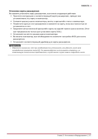
Глава 2: Установка оборудования | 17 B660GTA Установка карты расширения Вы можете установить карту расширения, выполнив следующие действия: • Прочтите инструкцию к соответствующей карте расширения, прежде чем устанавливать эту карту в компьютер. • Снимите крышку шасси компьютера, винты и кронштейн...
Page 74 - �6 Настройка переключателя; JCMOS1: Перемычка очистки CMOS; Указания по очистке CMOS:; Отсоедините питание переменного тока.
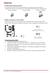
18 | Глава 2: Установка оборудования 2�6 Настройка переключателя На рисунке показано, как установить перемычки. Когда колпачковая перемычка помещена на контакты, она «замкнута», в противном случае перемычка «разомкнута». Контакт разомкнут Контакт замкнут Контакт 1-2 замкнут JCMOS1: Перемычка очистки...
Page 75 - �7 Штыревые соединители и разъемы; ATX: разъем источника питания ATX; правильной ориентации.
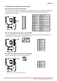
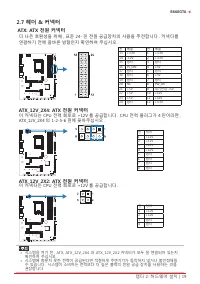
Глава 2: Установка оборудования | 19 B660GTA 2�7 Штыревые соединители и разъемы ATX: разъем источника питания ATX Для лучшей совместимости рекомендуется использовать для этого разъема стандартный 24-контактный источник питания ATX. Перед подключением разъема убедитесь в правильной ориентации. Pin As...
Page 76 - Подключите динамик шасси к этому штыревому соединителю.
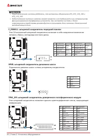
20 | Глава 2: Установка оборудования » » Перед включением системы убедитесь, что вставлены оба разъема ATX, ATX_12V_2X4 и ATX_12V_2X2. » » Недостаточное питание системы может привести к нестабильности или неправильному функционированию периферийных устройств. При настройке системы с более энерг...
Page 77 - Эти разъемы подключаются к жестким дискам SATA через кабели SATA.; периферийным устройствам.; панели; самым разным внешним периферийным устройствам.
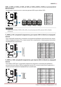
Глава 2: Установка оборудования | 21 B660GTA SATA_1/ SATA_2/ SATA_3/ SATA_4/ SATA_5/ SATA_6/SATA_7/SATA_8: разъемыSerial ATA 6,0 Гбит/с Эти разъемы подключаются к жестким дискам SATA через кабели SATA. Pin Assignment1 Ground 2 TX+ 3 TX- 4 Ground 5 RX- 6 RX+ 7 Ground » » Когда слот M.2(M2_PCIEG3_32G...
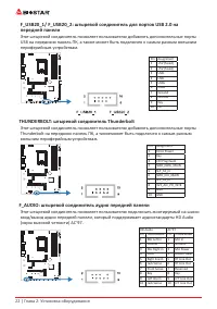
Page 78 - передней панели; THUNDERBOLT: штыревой соединитель Thunderbolt; внешним периферийным устройствам.; F_AUDIO: штыревой соединитель аудио передней панели
22 | Глава 2: Установка оборудования F_USB20_1/ F_USB20_2: штыревой соединитель для портов USB 2�0 на передней панели Этот штыревой соединитель позволяет пользователю добавлять дополнительные порты USB на переднюю панель ПК, а также может быть подключен к самым разным внешним периферийным устройства...
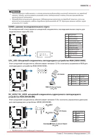
Page 79 - COM1: разъем последовательного порта
Глава 2: Установка оборудования | 23 B660GTA » » Рекомендуется подключать к этому разъему аудиомодуль высокой четкости на передней панели, чтобы использовать возможности материнской платы для воспроизведения звука высокой четкости. » » Попробуйте отключить функцию «Обнаружение разъема на передне...
Page 80 - Эти светодиоды показывают состояние материнской платы.; - указывает, что графический процессор; устройство не обнаружено или не работает.; Светодиоды; Штыревой соединитель светодиода RGB
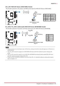
24 | Глава 2: Установка оборудования » » Убедитесь, что к вашему светодиодному устройству подключен правильный контакт, неправильное подключение может повредить светодиодное устройство или материнскую плату. » » Разъем 12V_LED поддерживает до 5050 светодиодных лент RGB с максимальной номинально...
Page 81 - Глава 3: UEFI BIOS и программное обеспечение | 25; Глава 3: UEFI BIOS и программное обеспечение; �1 Настройка UEFI BIOS
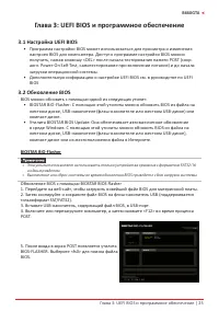
Глава 3: UEFI BIOS и программное обеспечение | 25 B660GTA Глава 3: UEFI BIOS и программное обеспечение 3�1 Настройка UEFI BIOS • Программа настройки BIOS может использоваться для просмотра и изменения настроек BIOS для компьютера. Доступ к программе настройки BIOS можно получить, нажав клавишу <...
Page 82 - 6 | Глава 3: UEFI BIOS и программное обеспечение
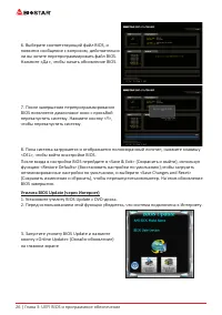
26 | Глава 3: UEFI BIOS и программное обеспечение 6. Выберите соответствующий файл BIOS, и появится сообщение с вопросом, действительно ли вы хотите перепрограммировать файл BIOS. Нажмите «Да», чтобы начать обновление BIOS. 7. После завершения перепрограммирования BIOS появляется диалоговое окно с п...
Page 83 - Глава 3: UEFI BIOS и программное обеспечение | 27
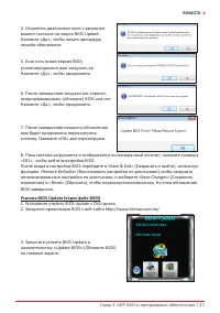
Глава 3: UEFI BIOS и программное обеспечение | 27 B660GTA 4. Откроется диалоговое окно с запросом вашего согласия на запуск BIOS Update. Нажмите «Да», чтобы начать процедуру онлайн-обновления. 5. Если есть новая версия BIOS, утилитапредложит вам загрузить ее. Нажмите «Да», чтобы продолжить. 6. После...
Page 84 - 8 | Глава 3: UEFI BIOS и программное обеспечение; Резервное копирование BIOS
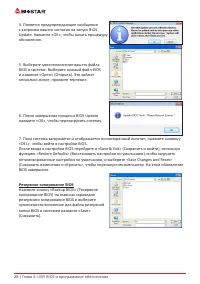
28 | Глава 3: UEFI BIOS и программное обеспечение 4. Появится предупреждающее сообщение с запросом вашего согласия на запуск BIOS Update. Нажмите «OK», чтобы начать процедуру обновления. 5. Выберите местоположение вашего файла BIOS в системе. Выберите нужный файл BIOS и нажмите «Open» (Открыть). Это...
Page 85 - Глава 3: UEFI BIOS и программное обеспечение | 29; �3 Программное обеспечение; Установка программного обеспечения; установки драйвера, если включена функция автозапуска.; Запуск программного обеспечения; Утилита BIOScreen
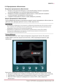
Глава 3: UEFI BIOS и программное обеспечение | 29 B660GTA 3�3 Программное обеспечение Установка программного обеспечения 1. Вставьте установочный DVD-диск в оптический привод. Появится программа установки драйвера, если включена функция автозапуска. 2. Выберите установку программного обеспечения, а ...
Page 86 - 0 | Глава 3: UEFI BIOS и программное обеспечение; Информация о системе
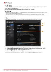
30 | Глава 3: UEFI BIOS и программное обеспечение RACING GT EVO RACING GT EVO – это простая в использовании программа, которая объединяет несколько утилит BIOSTAR и позволяет пользователям одновременно и легко настраивать эти утилиты. » » Содержание меню RACING GT EVO будет немного отличаться в зав...
Page 87 - Глава 3: UEFI BIOS и программное обеспечение | 31
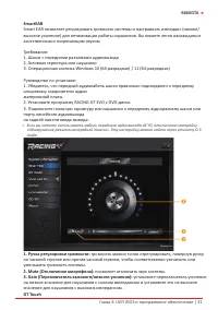
Глава 3: UEFI BIOS и программное обеспечение | 31 B660GTA SmartEAR Smart EAR позволяет регулировать громкость системы и настраивать импеданс (низкое/ высокое усиление) для оптимизации работы наушников. Вы можете легко наслаждаться качественным и потрясающим звуком. Требования: 1. Шасси с передними р...
Page 88 - 2 | Глава 3: UEFI BIOS и программное обеспечение
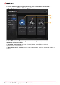
32 | Глава 3: UEFI BIOS и программное обеспечение GT Touch позволяет настраивать нормальный, эко- и спортивный режимы при запускепрограммы RACING GT EVO в среде Windows. 1� Normal (Нормальный режим): уравновешивает потребление энергии и производительность системы. 2� ECO Mode (Эко-режим): экономит э...
Page 89 - Глава 3: UEFI BIOS и программное обеспечение | 33; • Синхронизация памяти:
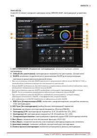
Глава 3: UEFI BIOS и программное обеспечение | 33 B660GTA Vivid LED DJ Vivid LED DJ может настроить цветовую схему ARMOR GEAR, светодиодное устройство RGB. 1� LED COMMANDER (Управление светодиодами): позволяет выбрать режим светодиодов. • Default (По умолчанию): светодиодная подсветка по умолчанию....
Page 90 - 4 | Глава 3: UEFI BIOS и программное обеспечение
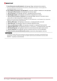
34 | Глава 3: UEFI BIOS и программное обеспечение 7� Auto (Автоматический режим): светодиоды будут автоматически менять » » Если вы выберете автоматический режим, цветовая палитра и полоса яркости светодиодов будут отключены. 8� LED SPARKLE (Сверкание светодиодов): позволяет выбрать сверкание свет...
Page 91 - Глава 3: UEFI BIOS и программное обеспечение | 35
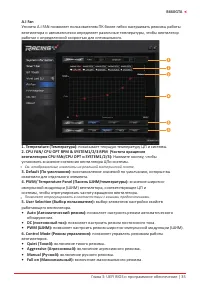
Глава 3: UEFI BIOS и программное обеспечение | 35 B660GTA A�I Fan Утилита A.I FAN позволяет пользователям ПК более гибко настраивать режимы работы вентилятора и автоматически определяет различные температуры, чтобы вентилятор работал с определенной скоростью для оптимального. 1� Temperature (Темпера...
Page 92 - 6 | Глава 3: UEFI BIOS и программное обеспечение; Аппаратный мониторинг; частоту вращения вентилятора и температуру.; � CPU Temperature/System Temperature/ MOS Temperature; показывает текущую температуру ЦП температура Mos и системы.
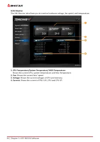
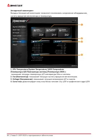
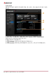
36 | Глава 3: UEFI BIOS и программное обеспечение Аппаратный мониторинг Вкладка Аппаратный мониторинг позволяет отслеживать напряжение оборудования, частоту вращения вентилятора и температуру. 1� CPU Temperature/System Temperature/ MOS Temperature (Температура ЦП/Температура системы/Температура MOS ...
Page 93 - Глава 3: UEFI BIOS и программное обеспечение | 37
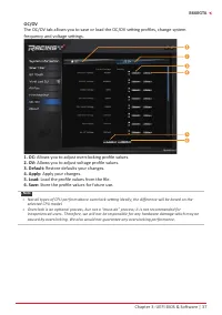
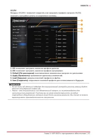
Глава 3: UEFI BIOS и программное обеспечение | 37 B660GTA OC/OV Вкладка <OC/OV> позволяет сохранять или загружать профили настроек OC/OV, изменять настройкичастоты и напряжения системы. 1� OC: позволяет настроить значения профиля разгона. 2� OV: позволяет настроить значения профиля напряжения....
Page 94 - 8 | Глава 3: UEFI BIOS и программное обеспечение; О программе
38 | Глава 3: UEFI BIOS и программное обеспечение О программе Меню «О программе» для отображения информации о версии утилиты Racing GT EVO.
Page 95 - Глава 4: Полезная помощь; Установка драйвера; операционную систему.
Глава 4: Полезная помощь | 39 B660GTA Глава 4: Полезная помощь 4�1 Установка драйвера После установки операционной системы вставьте полный установочный DVD-диск в оптический привод и установите драйвер для повышения производительности системы. После того, как вы вставите DVD-диск, появится следующее...
Page 96 - Звуковой код BIOS AMI; Звуковые коды загрузочного блока; Звуковые POST-коды BIOS; Количество; Код Описание
40 | Глава 4: Полезная помощь 4�2 Звуковой код BIOS AMI Звуковые коды загрузочного блока Количество Описание Непрерывно Ошибка определения размера памяти или модуль памяти не найден Звуковые POST-коды BIOS Количество Описание 1 Успешная загрузка. 8 Ошибка памяти дисплея (системный видеоадаптер) 4�3 ...
Page 98 - Поиск и устранение неисправностей; Неисправность; Перегрев ЦП; это означает, что активирована функция защиты ЦП.
42 | Глава 4: Полезная помощь 4�4 Поиск и устранение неисправностей Неисправность Решение 1. В системе отсутствует питание. Светодиод питанияне светится; вентилятор блока питания не работает 2. Индикатор на клавиатуре не светится. 1. Убедитесь, что кабель питания надежно подключен. 2. Замените кабел...
Page 99 - Функции RAID; Особенности и преимущества
Глава 4: Полезная помощь | 43 B660GTA 4�5 Функции RAID RAID Definitions В системе RAID 0 данные разделены на блоки, которые записываются на все диски в массиве. Одновременное использование нескольких дисков (как минимум 2) обеспечивает превосходную производительность ввода- вывода. Эту производитель...
Page 101 - Технология Intel® OptaneTM (питаться от памяти 3D XPoint); Характеристики и преимущества :
Глава 4: Полезная помощь | 45 B660GTA 4�6 Технология Intel® Optane™ (питаться от памяти 3D XPoint) С помощью технологии Intel® Optane ™ вы можете раскрыть всю мощь своего процессора вместо того, чтобы он работал на малую долю своей мощности. Для устранения этого узкого места требуется более качестве...
Page 102 - Эта страница намеренно оставлена пустой.
46 | Глава 4: Полезная помощь Эта страница намеренно оставлена пустой.
Page 103 - FCC 조항; 이기기는 FCC 조항제 15 부에 의해 심사되며 Class B 급디지털장치제한에부합됩니다 .; 면책 설명; 본설명서내용은 BIOSTAR; 정전기방지 조작 규칙; 정전기는고객님의 설비에심한손상을줄수있으므로 메인보드및다른시스템 설비를
FCC 조항 이기기는 FCC 조항제 15 부에 의해 심사되며 Class B 급디지털장치제한에부합됩니다 . 이조항은설치중에발생할수있는유해무선주파수간섭을제한하고 합리적인예방조치를제공합니다 .이기기는사용시무선주파수방사선이발생될 수 있으므로본설명서에따라설치및사용을 하지않는경우무선통신장치와의간섭이 발생할 수 있습니다 . 다만특정설치시간섭이발생될 수 있습니다 . 본기기를끄거나재시작시여전히라디오나 TV 수신에간섭하는 경우사용자는아래사항 중한가지또는여러가지방법을사용하여전파간섭을줄일수있습니다 : • 재설치또는수신안테나를조절합니다 .• 본기기와수신설...
Page 105 - 목차; 챕터 1: 들어가는 글 ������������������������������������������������������������������������������������������������
목차 | 3 B660GTA 목차 챕터 1: 들어가는 글 ������������������������������������������������������������������������������������������������ 4 1.1 시작하기에 앞서 ................................................................................................................................4 1.2 패키지 체크리스트 ................
Page 106 - 패키지 체크리스트
4 | 챕터 1: 들어가는 글 챕터 1: 들어가는 글 1�1 시작하기에 앞서 우선 , 바이오스타제품을선택해주셔서감사합니다 . 메인보드를설치하기 전에아래의내용을준수하고있는지확인 바랍니다: • 작업에적합한조명아래건조하고안정적인작업환경을갖추시기 바랍니다 .• 작업전컴퓨터전원콘센트의연결을차단시키시기 바랍니다 .• 정전기방지비닐에서메인보드를꺼내기전 , 접지설비에안전하게접촉하거나정전기를제 거하는접지용손목스트랩을사용하여적절히접지하시기바랍니다 . • 필요한경우가아니면마더보드상의부품또는보드의후면과의접촉을피하시기 바랍니다 . 보드의모서리를잡고보드를구...
Page 111 - ILM 브라켓을 위로 젖힌후 CPU 보호덮개를 제거합니다 .
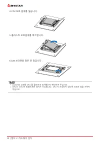
챕터 2: 하드웨어 설치 | 9 B660GTA 챕터 2: 하드웨어 설치 2�1 CPU 설치 1 단계 : 메인보드의 CPU 소켓위치를확인해 주십시오 . » 설치 전에 핀 보호 커버를 제거하고 , 추후 사용을 위해 잘 보관하시기 바랍니다 . CPU 를 제거 시소켓의 핀이 휘어지지 않도록 빈 소켓에 핀 보호 커버를 덮어 주십시오 . » 메인보드에 두 가지 유형의핀 보호 커버가적용됩니다 . 아래 안내문을 참조하여 핀 보호 커버를제거해 주십시오 . 2 ILM 브라켓을 위로 젖힌후 CPU 보호덮개를 제거합니다 . 3 CPU 를 소켓에 정확하게...
Page 112 - ILM 브라켓을 덮은 후 잠급니다 .
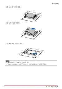
10 | 챕터 2: 하드웨어 설치 4 CPU 보호 덮개를 덮습니다 . 5 플라스틱 보호덮개를 제거합니다 . 6 ILM 브라켓을 덮은 후 잠급니다 . » LGA1700 소켓용 CPU 를 올바르게 설치했는지 확인하여 주십시오 . » CPU 는 오직 한 방향으로만 설치가 가능합니다 . CPU 가 손상되지 않도록 과도한 힘을 가하지 마십시오 .
Page 115 - �4 시스템 메모리 설치; DDR4 모듈
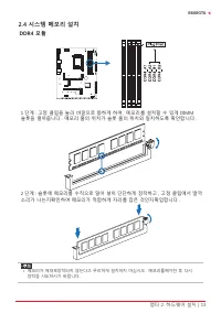
챕터 2: 하드웨어 설치 | 13 B660GTA 2�4 시스템 메모리 설치 DDR4 모듈 1 단계 : 고정 클립을 눌러 바깥으로 향하게 하여 , 메모리를 설치할 수 있게 DIMM 슬롯을 열어줍니다 . 메모리 홈의 위치가 슬롯 홈의 위치와 일치하도록 확인합니다 . 2 단계 : 슬롯에 메모리를 수직으로 밀어 넣어 단단하게 장착하고 , 고정 클립에서 딸깍 소리가 나는지확인하여 메모리가 적합하게 자리를 잡은 것인지확입합니다 . » 메모리가 제대로장착되지 않는다고 무리하게 설치하지 마십시오 . 메모리를제거한 후 다시 장착을 시도하시기 바랍니...
Page 116 - 메모리 용량; DIMM 소켓 위치; 듀얼 채널 메모리 설치; 듀얼 채널 상태
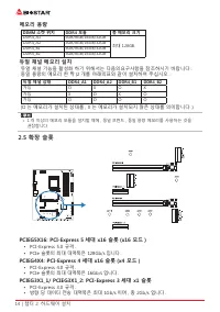
14 | 챕터 2: 하드웨어 설치 메모리 용량 DIMM 소켓 위치 DDR4 모듈 총 메모리 크기 DDR4_A1 4GB/8GB/16GB/32GB 최대 128GB. DDR4_A2 4GB/8GB/16GB/32GB DDR4_B1 4GB/8GB/16GB/32GB DDR4_B2 4GB/8GB/16GB/32GB 듀얼 채널 메모리 설치 듀얼 채널 기능을 활성화 하기 위해서는 다음의요구사항을 참조하시기 바랍니다 : 동일 용량의 메모리 한 짝 (2 개를 아래의표와 같이 설치하여 주십시오 . 듀얼 채널 상태 DDR4_A1 DDR4_A2 DDR4_B1 ...
Page 120 - 확장 카드 설치; 다음의 단계에 따라 확장 카드를 장착할 수 있습니다 :
18 | 챕터 2: 하드웨어 설치 확장 카드 설치 다음의 단계에 따라 확장 카드를 장착할 수 있습니다 : • 컴퓨터에 확장 카드를 설치하기 전에 확장 카드의 안내문을 읽으시기 바랍니다 .• 컴퓨터에서 케이스 커버 , 볼트 , 슬롯 브라켓을 제거합니다 .• 확장 슬롯에 카드를 놓고 , 슬롯에 완벽하게 장착이 되도록 카드를 아래로 눌러 줍니다 . • 카드의 금속 브라켓을 케이스 후면 패널에 드라이버를 이용하여 고정합니다 .( 이 단계는 VGA 카드 설치에만 해당됩니다 .) • 컴퓨터 케이스 커버를 다시 덮어씁니다 .• 필요한 경우 , ...
Page 123 - 이 커넥터들은 SATA 케이블을 통해 SATA 하드 디스크 드라이브에 연결됩니다 .
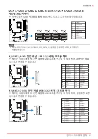
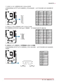
챕터 2: 하드웨어 설치 | 21 B660GTA SATA_1/ SATA_2/ SATA_3/ SATA_4/ SATA_5/ SATA_6/SATA_7/SATA_8: 시리얼 ATA 커넥터 이 커넥터들은 SATA 케이블을 통해 SATA 하드 디스크 드라이브에 연결됩니다 . 핀 배열 1 Ground 2 TX+ 3 TX- 4 Ground 5 RX- 6 RX+ 7 Ground » SATA 모드가 M.2 (M2_PCIEG3_32G_SATA _1) 슬롯을 점유하면 SATA _8 커넥터가 비활성화됩니다 . F_USB32_A-5G: 전면 패널 USB 3...
Page 124 - 이 헤더는 사용자에게 PC 전면 패널에 USB 포트를 추가할 수 있게 하며 , 광범위한; THUNDERBOLT: Thunderbolt 커넥터; PC 전면패널은부가된 Thunderbolt 포트를지원하며주변장치에도연결즉시사용가능합
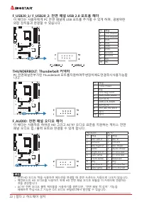
22 | 챕터 2: 하드웨어 설치 F_USB20_1/ F_USB20_2: 전면 패널 USB 2�0 포트용 헤더 이 헤더는 사용자에게 PC 전면 패널에 USB 포트를 추가할 수 있게 하며 , 광범위한 외장 장치들과 연결할 수 있습니다 . 핀 배열 1 +5V (fused) 2 +5V (fused) 3 USB- 4 USB- 5 USB+ 6 USB+ 7 Ground 8 Ground 9 Key 10 NC THUNDERBOLT: Thunderbolt 커넥터 PC 전면패널은부가된 Thunderbolt 포트를지원하며주변장치에도연결즉시사용가능합 니...
Page 125 - 본 메인 보드는 1 개의 직렬포트가 있으며 RS-232 커넥터를 연결할 수 있습니다 .
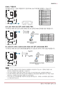
챕터 2: 하드웨어 설치 | 23 B660GTA COM1: 직렬포트 본 메인 보드는 1 개의 직렬포트가 있으며 RS-232 커넥터를 연결할 수 있습니다 . 핀 배열 1 캐리어 검출 2 데이터 수신 3 데이터 전송 4 데이터 단말 준비 5 접지 신호 # 6 데이터 세트 준비 7 전송 요구 # 8 전송 취소 # 9 벨소리 표시기 10 Key 12V_LED: RGB LED 장치 (5050 SMD) 헤더 이 헤더는 RGB LED 장치 (5050 SMD) 에 12V 전력과 RGB 컨트롤 핀을 제공합니다 . 핀 케이블 색상 배열1 12V (B...
Page 126 - Debug LED: 디버그 LED 표시등; 이 LED 는 마더 보드의 상태를 나타냅니다 .
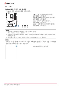
24 | 챕터 2: 하드웨어 설치 2�8 LEDs Debug LED: 디버그 LED 표시등 이 LED 는 마더 보드의 상태를 나타냅니다 . CPU - CPU 가 감지되지 않았거나 실패했음을 나타냅니다 . DRAM - DRAM 이 감지되지 않았거나 실패했음을 나타냅니다 . VGA - GPU 가 감지되지 않거나 실패했음을 나타냅니다 . BOOT - 부팅 장치가 감지되지 않거나 실패했음을 나타냅니다 . » 컴퓨터를 시작하면 LED 표시등이 다음 순서로 켜집니다 . CPU → DRAM → VGA → BOOT » 컴퓨터가 준비되면 LED 표...
Page 127 - �1 UEFI 바이오스 설정; • 바이오스 설정 프로그램은 컴퓨터의 바이오스 설정을 보거나 변경할 때
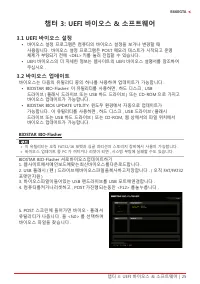
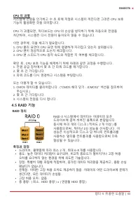
챕터 3: UEFI 바이오스 & 소프트웨어 | 25 B660GTA 챕터 3: UEFI 바이오스 & 소프트웨어 3�1 UEFI 바이오스 설정 • 바이오스 설정 프로그램은 컴퓨터의 바이오스 설정을 보거나 변경할 때 사용됩니다 . 바이오스 설정 프로그램은 POST 메모리 테스트가 시작되고 운영 체제가 부팅되기 전에 <DEL> 키를 눌러 진입할 수 있습니다 . • UEFI 바이오스의 더 자세한 정보는 웹사이트의 UEFI 바이오스 설명서를 참조하여 주십시오 . 3�2 바이오스 업데이트 바이오스는 다음의 유틸리티 중의...
Page 130 - 바이오스의 백업
28 | 챕터 3: UEFI 바이오스 & 소프트웨어 5. 시스템의 바이오스 파일이 있는 위치를 선택하신 후 , 적합한 바이오스 파일이 맞는지 확인하고 “열기 (Open)”를 클릭합니다 . 이 과정은 몇 분의 시간이 필요하니 , 진행되는 동안 잠시 기다리시기 바랍니다 . 6. 바이오스업데이트 과정을 마친 후 , 시스템을 다시 부팅할 것인지 물을 것이며 , “OK”를 클릭하면 다시 부팅합니다 . 7. 시스템이 부팅되고 , 풀 스크린 로고가 등장하는 동안 , <DEL> 키를 눌러 바이오스 설정에 진입합니다 . 바이오스 ...
Page 131 - 소프트웨어의 설치; 광학 드라이브에 시작 DVD 를 넣은 후 , 자동 실행 기능이 활성화 되면 드라이버; 소프트웨어의 실행; 부트 로고를 업데이트 하기 위해 아래 지시사항을 순서대로 준수하시기 바랍니다 :
챕터 3: UEFI 바이오스 & 소프트웨어 | 29 B660GTA 3�3 소프트웨어 소프트웨어의 설치 1. 광학 드라이브에 시작 DVD 를 넣은 후 , 자동 실행 기능이 활성화 되면 드라이버 설치 프로그램이 나타납니다 . 2. 소프트웨어 설치를 선택하고 , 각각의 소프트웨어 타이틀을 클릭합니다 .3. 스크린 상의 지시사항을 준수한 후 , 설치를 마칩니다 . 소프트웨어의 실행 설치 과정을 마친 후 , 데스크톱에서 소프트웨어 아이콘을 볼 수 있습니다 . 아이콘을 더블 - 클릭하여 실행합니다 . » 다음의 소프트웨어와 관련된 모든...
Page 132 - 시스템 정보; 이 시스템 정보 탭은 시스템의 기본적인 정보와 사양을 제공합니다 .
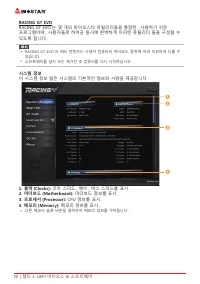
30 | 챕터 3: UEFI 바이오스 & 소프트웨어 RACING GT EVO RACING GT EVO 는 몇 개의 바이오스타 유틸리티들을 통합한 , 사용하기 쉬운 프로그램이며 , 사용자들로 하여금 동시에 완벽하게 이러한 유틸리티 들을 구성할 수 있도록 합니다 . » RACING GT EVO 의 메뉴 컨텐츠는 사용자 컴퓨터의 마더보드 종류에 따라 미묘하게 다를 수 있습니다 . » 소프트웨어를 설치 또는 제거한 후 컴퓨터를 다시 시작하십시오 . 시스템 정보 이 시스템 정보 탭은 시스템의 기본적인 정보와 사양을 제공합니다 . 1�...
Page 135 - RAZER 앱을 연결해메인보드 RGB 색상 동기화; LED 유형 프로젝트 설정을 동기화 할 수 있습니다 .
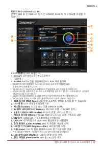
챕터 3: UEFI 바이오스 & 소프트웨어 | 33 B660GTA 비비드 LED DJ(Vivid LED DJ) 선명한 LED DJ 는 RGB LED 장치 인 ARMOR GEAR 의 색 구성표를 조정할 수 있습니다 . 1. LED 컴맨더 : LED 모델선택 . • Default: 모든설정값을기본값으로복구 . ( 파란불 ) • RAZER: RAZER 앱을 연결해메인보드 RGB 색상 동기화 » RAZER 모드를사용할경우 RACING GT EVO 소프트웨어를끄면 LED 조명이기본상태로돌아갑니다 . » RAZER 모드는 RAZER 소...
Page 137 - 현재 CPU 와 시스템 온도를 표시 .; 변경했던 한 가지 항목의 수치를 기본값으로 복구 .; 팬 속성이 실제 선택 작업을 조절하게 설정 .
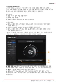
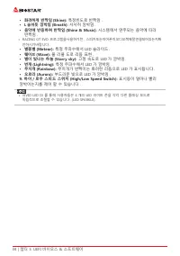
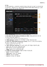
챕터 3: UEFI 바이오스 & 소프트웨어 | 35 B660GTA A�I Fan A.I FAN 유틸리티는 스마트하게 사용자로 하여금 팬의 동작 모드를 커스터마이징 할 수 있게 하고 , 자동으로 각기 다른 온도를 감지하여 최적의 쿨링 성능을 낼 수 있게 지정된 속도에서 팬의 동작을 조절합니다 . 1� 온도 (Temperature): 현재 CPU 와 시스템 온도를 표시 . 2� CPU FAN/ CPU OPT RPM & SYSTEM1/2/3 RPM: 버튼을 클릭하여 CPU 팬 , 시스템 팬 상태 값을 설정합니다 . » 디스...
Page 139 - 추후 사용을 위해 프로파일 수치를 저장 .
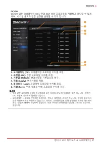
챕터 3: UEFI 바이오스 & 소프트웨어 | 37 B660GTA OC/OV OC/OV 탭은 오버클럭킹 (OC)/ 전압 (OV) 설정 프로파일을 저장하고 로딩할 수 있게 하여 , 시스템 클럭과 전압 설정을 변경할 수 있게 합니다 . 1� 오버클럭킹 (OC): 오버클럭킹 프로파일 수치를 조정 . 2� 과전압 (OV): 전압 프로파일 수치를 조정 . 3� 기본값 (Default): 변경사항을 기본값으로 복구 . 4� 적용 (Apply): 변경사항을 적용 . 5� 불러오기 (Load): 파일에서 프로파일 수치를 로딩 . 6� 저장...
Page 140 - About 메뉴는 버전 정보를 표시합니다 .
38 | 챕터 3: UEFI 바이오스 & 소프트웨어 About About 메뉴는 버전 정보를 표시합니다 .
Page 141 - 설정 가이드는 사용자의 마더보드와 운영 체제를 자동으로 감지합니다 .; A� 드라이버 설치
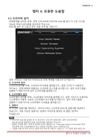
챕터 4: 유용한 도움말 | 39 B660GTA 챕터 4: 유용한 도움말 4�1 드라이버 설치 운영체제를 설치한 후에 , 광학 드라이브에 드라이버 DVD 를 넣고 더 나은 시스템 성능을 위해 드라이버를 설치하여 주십시오 .DVD 를 넣은 후 다음과 같은 창을 보게 될 것입니다 . 설정 가이드는 사용자의 마더보드와 운영 체제를 자동으로 감지합니다 . A� 드라이버 설치 드라이버 설치를 위해 , 드라이버 아이콘을 클릭합니다 . 설정 가이드가 사용자의 마더보드 , 운영 체제와 호환되는 드라이버 리스트를 표시합니다 . 설치 프로그램을 실행...
Page 142 - AMI 바이오스 비프 코드; 부트 블록 비프 코드; POST 바이오스 비프 코드; 비프음 횟수; �3 AMI 바이오스 포스트 코드; 코드 설명
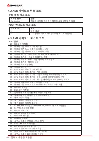
40 | 챕터 4: 유용한 도움말 4�2 AMI 바이오스 비프 코드 부트 블록 비프 코드 비프음 횟수 설명 Continuing 메모리 사이징 에러 또는 메모리 모듈 발견되지 않음 POST 바이오스 비프 코드 비프음 횟수 설명 1 부팅 성공 8 디스플레이 메모리 에러 ( 시스템 비디오 어댑터 ) 4�3 AMI 바이오스 포스트 코드 코드 설명 10 PEI 코어 시작됨11 메모리 이전 CPU 초기화 시작됨15 메모리 이전 노스 브릿지 초기화 시작됨19 메모리 이전 사우스 브릿지 초기화 시작됨2B 메모리 초기화 . 직렬 프레즌스 검출 (S...
Page 144 - 전원 케이블이 제대로 연결되어 있는지
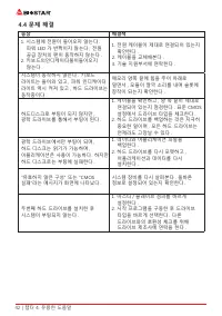
42 | 챕터 4: 유용한 도움말 4�4 문제 해결 증상 해결책 1. 시스템에 전원이 들어오지 않는다 . 파워 LED 가 반짝이지 않는다 ; 전원 공급 장치의 팬이 동작하지 않는다 . 2. 키보드의인디케이터불이들어오지 않는다 . 1. 전원 케이블이 제대로 연결되어 있는지 확인한다 . 2. 케이블을 교체해본다 .3. 기술 지원부서에 연락한다 . 시스템이 동작하지 않는다 . 키보드 라이트는 들어와 있고 , 파워 인디케이터 라이트 역시 켜져 있고 , 하드 드라이브는 동작중이다 . 메모리 양쪽 끝에 힘을 주어 아래로 밀면서 , 모듈이 딸깍...
Page 145 - CPU 의 과열; RAID 기능; RAID 정의; 오차를 요구하지 않는 환경을 위해 의도된 기술입니다 .
챕터 4: 유용한 도움말 | 43 B660GTA CPU 의 과열 시스템에 전원을 인가하고 수 초 후에 저절로 시스템이 꺼진다면 그것은 CPU 보호 기능이 활성화된 것을 의미합니다 . CPU 가 과열되면 , 마더보드는 CPU 의 손상을 방지하기 위해 자동으로 전원을 차단하며 , 시스템은 다시 전원이 들어오지 않을 수 있습니다 . 이런 경우에 , 더블 체크가 필요합니다 :1. CPU 쿨러 표면이 CPU 표면 위에 평평하게 자리잡고 있는지 살펴봅니다 .2. CPU 팬이 정상적으로 도는지 체크합니다 .3. CPU 팬 스피드가 CPU 동작 ...
Page 146 - 컨트롤러가 정상적인 다른 드라이브로 전환합니다 .; 특징과 장점; • 문제점 : 데이터 중복을 위해 RAID 레벨 1 과 같이 두 배의 가용 디스크 공간이
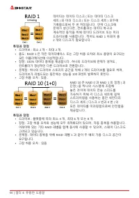
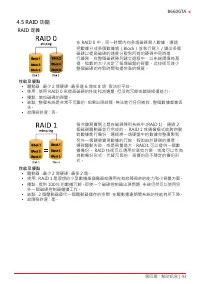
44 | 챕터 4: 유용한 도움말 데이터는 데이터 디스크 ( 또는 데이터 디스크 세트 ) 와 미러 디스크 ( 또는 디스크 세트 ) 모두에 기록함으로써 두 번 저장됩니다 . 만약 디스크에 문제가 생긴다면 , 컨트롤러는 데이터 복구과 계속적인 동작을 위해 데이터 드라이브 또는 미러 드라이브를 사용합니다 . 적어도 RAID 1 어레이 용 2 개의 디스크가 필요합니다 . 특징과 장점 • 드라이브 : 최소 2 개 – 최대 2 개 .• 용도 : RAID 1 은 작은 데이터베이스 또는 고장 허용 오차와 최소 용량이 요구되는 모든 어플리케이션에 ...
Page 147 - • 문제점 : 하나의 디스크와 같이 개별적인 블록 데이터 전송율은 동일합니다 . 쓰기
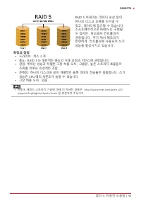
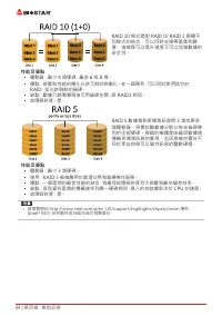
챕터 4: 유용한 도움말 | 45 B660GTA RAID 5 어레이는 데이터 손상 없이 하나의 디스크 오류를 이겨낼 수 있고 , 데이터에 접근할 수 있습니다 . 소프트웨어적으로 RAID5 는 구현될 수 있지만 , 하드웨어 컨트롤러가 권장됩니다 . 추가 캐쉬 메모리가 빈번하게 컨트롤러에 사용되어 쓰기 성능을 향상시키고 있습니다 . 특징과 장점 • 드라이브 : 최소 3 개 .• 용도 : RAID 5 는 일반적인 용도의 거래 과정과 서비스에 권장됩니다 .• 장점 : 뛰어난 성능과 탁월한 고장 허용 오차 , 고용량 , 높은 스토리지 효율등...
Page 148 - 인텔l
46 | 챕터 4: 유용한 도움말 4�6 인텔 ® 옵테인™ 기술 (3D XPoint 메모리로 구동) 인텔 ® 옵테인™ 기술을 통해, 강력한 프로세서의 힘을 체험할 수 있습니다. 병목현상을 제거하기 위해 빠르고, 가성비 뛰어나고, 비-휘발성의 향상된 스토리지 메모리가 요구되어 집니다. 인텔 ® 옵테인 기술은 빅데이터, 고-성능 컴퓨팅, 가상화 기술, 스토리지, 클라우드, 게이밍, 기타 여러가지 어플리케이션을 혁신시킬 수 있는 잠재력을 가지고 있습니다. 특징과 장점 : • 거대한 메모리 기반 데이터 베이스• 빠른 시스템 복구• 낮은 레...
Page 149 - 防靜電操作規則
FCC 條款 本裝置經測試,證實依據 FCC 規範第 15 篇規定,符合 Class B 數位裝置的限制。這些限 制意 旨在提供合理的保護以防範有害的干擾。本設備會產生、使用並發出無線射頻能量,如未 依指示進行安裝與使用,可能會對無線電通訊造成有害的干擾。然而,無法保證在任一特 定安裝情況下不會產生任何干擾。如果本設備確實對無線電或電視收訊造成有害的干擾 ( 可 透過開啟和關閉設備電源的方式確定 ),則我們鼓勵使用者嘗試下列其中一項或多項方式來 改善干擾情況: • 重新調整接收天線的方向或位置。 • 增加設備與接收器之間的間隔距離。 • 將設備連接至與接收器所接電路不同的電源插座。 • 諮詢經...
Page 150 - 目錄; 第一章 : 主板介绍 ������������������������������������������������������������������������������������������������������
2 | 目錄 目錄 第一章 : 主板介绍 ������������������������������������������������������������������������������������������������������ 3 1.1 前言 ............................................................................................................................................... 3 1.2 包裝配件 ...............
Page 151 - Serial ATA
第一章 : 主板介绍 | 3 B660GTA 第一章 : 主板介绍 1�1 前言 感謝您選購我們的產品,在開始安裝主板前,請仔細閱讀以下安全指導说明: • 選擇清潔穩定的工作環境。 • 操作前請確保電腦關閉電源。 • 從抗靜電袋取出主板之前,先使用靜電消除器或防靜電手環去除靜電以確保安全。 • 避免觸摸主板上的零件,手持電路板的邊緣,請勿折彎或按壓電路板。 • 安裝之後,確認没有任何小零件置於機箱中,一些小的零件可能會引起電流短路並可能 損壞設備。 • 確保電腦遠離危險區域,如:高溫、潮濕、靠近水源的地方。須確保電腦遠離危險。 • 電腦的工作溫度應保持在 0-45℃之間。 • 為避免受傷,請注...
Page 152 - 主板特性
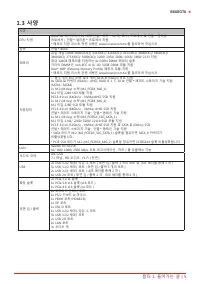
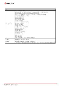
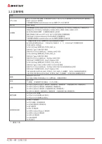
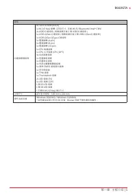
4 | 第一章 : 主板介绍 1�3 主板特性 規格 CPU 支援 第 12 代 LGA1700 架構 , 支援 Intel ® Core ™ i9/ i7/ i5/ i3 處理器和 Intel ® Pentium ® 處理器 / Intel ® Celeron ® 處理器 * 請瀏覽映泰網站 www.biostar.com.tw 獲得 CPU 的支援列表 晶片組 Intel ® B660 記憶體 支援雙通道 DDR4 5000+(OC)/ 4333(OC)/ 4266(OC)/ 4133(OC)/ 4000(OC)/ 3866(OC)/3800(OC)/ 3733(OC)/ 3600(OC)...
Page 156 - 步驟 2: 將 ILM 拉桿向上抬起並將 CPU 保護蓋掀起。
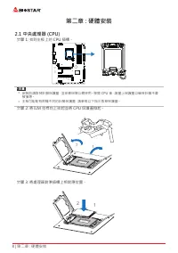
8 | 第二章 : 硬體安裝 第二章 : 硬體安裝 2�1 中央處理器 (CPU) 步驟 1: 找到主板上的 CPU 插槽。 » 安裝前請取掉針腳保護蓋,並妥善保管以備使用。移開 CPU 後,請蓋上保護蓋以確保針腳不會 被損壞。 » 主板可能配有兩種不同的針腳保護蓋,請參照以下指示取掉保護蓋。 步驟 2: 將 ILM 拉桿向上抬起並將 CPU 保護蓋掀起。 步驟 3: 將處理器對準插槽上相對應位置。
Page 159 - 此風扇接頭支援電腦上設置的冷卻風扇,風扇電纜和連接器可能因風扇製造商而有差
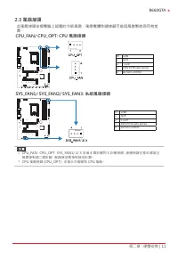
第二章 : 硬體安裝 | 11 B660GTA 2�3 風扇接頭 此風扇接頭支援電腦上設置的冷卻風扇,風扇電纜和連接器可能因風扇製造商而有差 異。 CPU_FAN/ CPU_OPT: CPU 風扇接頭 針 定義1 接地 2 +12V 3 FAN RPM rate sense 4 AI Fan Control SYS_FAN1/ SYS_FAN2/ SYS_FAN3: 系統風扇接頭 針 定義1 接地 2 +12V 3 FAN RPM rate sense 4 AI Fan Control » CPU_FAN,CPU_OPT,SYS_FAN1/ 2/ 3 支援 4 個針腳和 3 針腳接頭;接線時請...
Page 160 - DDR4 記憶體模組; 步驟 1: 向外按壓固定夾以解鎖 DIMM 插槽。 對準插槽上的 DIMM,以使 DIMM 上的
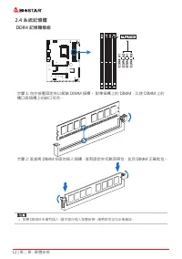
12 | 第二章 : 硬體安裝 2�4 系統記憶體 DDR4 記憶體模組 步驟 1: 向外按壓固定夾以解鎖 DIMM 插槽。 對準插槽上的 DIMM,以使 DIMM 上的 槽口與插槽上的缺口符合。 步驟 2: 垂直將 DIMM 牢固地插入插槽,直到固定夾扣跳回原位,並且 DIMM 正確就位。 » 如果 DIMM 未順利插入,請勿強行插入按壓安裝。請將其完全拉出後重試。
Page 161 - 記憶體容量; DIMM 插槽位置; 雙通道記憶安裝; 為啓動主板雙通道功能,使用記憶體模組必須符合以下要求: 成對安裝相同密度的記憶; 雙通道狀態
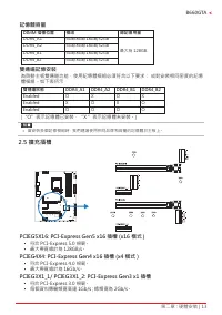
第二章 : 硬體安裝 | 13 B660GTA 記憶體容量 DIMM 插槽位置 模组 總記憶用量 DDR4_A1 4GB/8GB/16GB/32GB 最大為 128GB. DDR4_A2 4GB/8GB/16GB/32GB DDR4_B1 4GB/8GB/16GB/32GB DDR4_B2 4GB/8GB/16GB/32GB 雙通道記憶安裝 為啓動主板雙通道功能,使用記憶體模組必須符合以下要求: 成對安裝相同密度的記憶 體模組。如下表所示 雙通道狀態 DDR4_A1 DDR4_A2 DDR4_B1 DDR4_B2 Enabled O X O X Enabled X O X O Enabled ...
Page 165 - 安裝擴充卡
第二章 : 硬體安裝 | 17 B660GTA 安裝擴充卡 請參照以下步驟安裝擴充卡: • 安裝擴充卡前請閱讀擴充卡的相關指示說明。 • 打開電腦機箱後蓋,移除螺絲和插槽支架。 • 將擴充卡按照正確的方向插入插槽,直到擴充卡完全固定住。 • 用螺絲將擴充卡的金屬支架固定到機箱後置面板。( 僅安裝顯示卡時適用此步驟 ) • 將電腦機箱後蓋閉合。 • 開機。如有必要,可為擴充卡更改 BIOS 設定。 • 安裝擴充卡的驅動。 » 請注意,如果要安裝或卸下螺絲,則需要使用 M2 型螺絲起子。建議不要使用不符合規格的螺絲 起子,否則可能會造成螺絲損壞。
Page 167 - 此 10 針腳接頭包含開機,重新啓動,硬碟指示燈和電源指示燈。
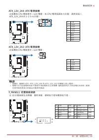
第二章 : 硬體安裝 | 19 B660GTA ATX_12V_2X4: ATX 電源插槽 此插槽為 CPU 電路提供 +12V 電壓。若 CPU 電源插頭為 4 針腳,請將其插入 ATX_12V_2X4 的 1-2-5-6 針腳。 針 定義 1 +12V 2 +12V 3 +12V 4 +12V 5 接地 6 接地 7 接地 8 接地 ATX_12V_2X2: ATX 電源插槽 此插槽為 CPU 電路提供 +12V 電壓。 針 定義 1 +12V 2 +12V 3 接地 4 接地 » 開機前,請確保 ATX、ATX_12V_2X4 和 ATX_12V_2X2 插槽都已插上電源。 » 電壓不足...
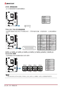
Page 168 - Serial ATA 接頭; 此接頭通過 SATA 數據線連接 SATA 硬碟。
20 | 第二章 : 硬體安裝 SPKR: 揚聲器接頭 此 4 針腳接頭提供您連接揚聲器。 針 定義1 +5V 2 N/A 3 N/A 4 揚聲器 TPM_SPI: TPM 安全模組接頭 此接頭可連接可信任安全平台模组系统,可用來儲存金鑰、認證與資料,並增加網路安 全性。 針 定義 針 定義 1 Key 2 N/A 3 N/A 4 N/A 5 Ground 6 +3V3_DUAL 7 TSPI_CLK 8 N/A 9 N/A 10 TSPI_MISO 11 N/A 12 TSPI_MISI 13 TSPI_CS# 14 Ground 15 N/A 16 N/A 17 TSPI_PIRQ# 18...
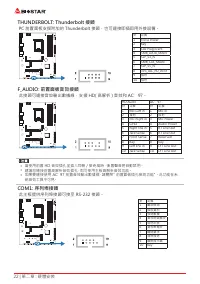
Page 170 - THUNDERBOLT: Thunderbolt 接頭; PC 前置面板支援附加的 Thunderbolt 接頭,也可連接即插即用外接設備。; 此主板提供序列埠接頭可接至 RS-232 接頭。
22 | 第二章 : 硬體安裝 THUNDERBOLT: Thunderbolt 接頭 PC 前置面板支援附加的 Thunderbolt 接頭,也可連接即插即用外接設備。 針 定義 1 Force Power 2 Key 3 CIO Plug Event 4 SMB_DATA_MAIN 5 SLP_S3_N 6 SMB_CLK_MAIN 7 SLP_S5_N 8 3V3_AIC_PD_INT# 9 接地 10 接地 F_AUDIO: 前置面板音效接頭 此接頭可連接音效輸出數據線,支援 HD( 高解析 ) 音效和 AC’97。 HD Audio AC’97 針 定義 針 定義 1 Mic Lef...
Page 171 - 此接頭提供 12V 電源與 RGB 控制訊號,可連接 RGB LED 裝置 (5050 SMD)。; 此接頭提供 5V 電源與數據控制訊號,可連接 ARGB LED 裝置 (WS2818B)。
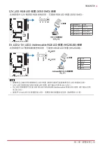
第二章 : 硬體安裝 | 23 B660GTA 12V_LED: RGB LED 裝置 (5050 SMD) 接頭 此接頭提供 12V 電源與 RGB 控制訊號,可連接 RGB LED 裝置 (5050 SMD)。 針 電纜顏色 定義 1 12V ( 黑色 ) VCC12 2 G ( 綠色 ) LED_GREEN 3 R ( 紅色 ) LED_RED 4 B ( 藍色 ) LED_BLUE 5V_LED1/ 5V_LED2: Addressable RGB LED 裝置 (WS2818B) 接頭 此接頭提供 5V 電源與數據控制訊號,可連接 ARGB LED 裝置 (WS2818B)。 針 定...
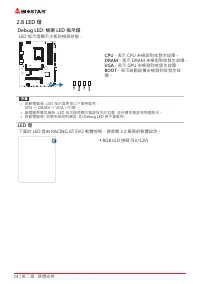
Page 172 - Debug LED: 檢測 LED 指示燈; LED 指示燈顯示主板的檢測狀態。; - 表示 DRAM 未檢測到或發生故障。; LED 燈; 下面的 LED 燈由 RACING GT EVO 軟體控制。請參閱 3.3 章節的軟體設定。
24 | 第二章 : 硬體安裝 2�8 LED 燈 Debug LED: 檢測 LED 指示燈 LED 指示燈顯示主板的檢測狀態。 CPU - 表示 CPU 未檢測到或發生故障。 DRAM - 表示 DRAM 未檢測到或發生故障。 VGA - 表示 GPU 未檢測到或發生故障。 BOOT - 表示啟動設備未檢測到或發生故 障。 » 啟動電腦後,LED 指示燈將按以下順序點亮: CPU → DRAM → VGA →引導。 » 當電腦準備就緒時,LED 指示燈將顯示錯誤發生的位置,並持續亮著直到問題解決。 » 啟動電腦後,如果未檢測到異常,則 Debug LED 將不會點亮。 LED 燈 下面的 ...
Page 173 - �1 UEFI BIOS 設定
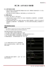
第三章 : UEFI BIOS 和軟體 | 25 B660GTA 第三章 : UEFI BIOS 和軟體 3�1 UEFI BIOS 設定 • BIOS 設定程式可用於查看與更改電腦的 BIOS 設定。開機進行自動檢測時,按 <DEL> 鍵可進入 BIOS 設定程式。 • 更多相關 UEFI BIOS 設置訊息,請參考網站上的 UEFI BIOS 手册。 3�2 更新 BIOS 以下任意一種工具都可以更新 BIOS: • BIOSTAR BIO-Flasher: 使用此工具,BIOS 可透過硬碟上的檔案更新、USB 驅動更 新或者 CD-ROM 更新。 • BIOSTAR BIOS...
Page 174 - BIOS 更新工具(通過網路)
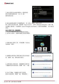
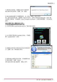
26 | 第三章 : UEFI BIOS 和軟體 7. BIOS 更新完成後則會彈出一個對話框, 要求您重新啟動系統。 按 <Y> 鍵 重新啟動系統。 8. 當系統啟動並顯示全螢幕標誌時,按 <DEL> 鍵進入 BIOS 設定。 進入 BIOS 設定程式後,請選擇 <Save & Exit>,使用 <Restore Defaults> 功能下載 系統優化預設值,然後選擇 <Save Changes and Reset> 以重新啟動電腦。 完成 BIOS 更新。 BIOS 更新工具(通過網路) 1. 用 DVD 驅動安裝 BIOS Up...
Page 175 - BIOS 更新工具(通過 BIOS 文件)
第三章 : UEFI BIOS 和軟體 | 27 B660GTA 7. 更新程式结束後,螢幕跳出提示您重新開 機引導系统的對話框。點擊”OK”重啟。 8. 當系統啟動並顯示全螢幕標誌時,按 <DEL> 鍵進入 BIOS 設定。 進入 BIOS 設定程式後,請選擇 <Save & Exit>,使用 <Restore Defaults> 功能下載 系統優化預設值,然後選擇 <Save Changes and Reset> 以重新啟動電腦。 完成 BIOS 更新。 BIOS 更新工具(通過 BIOS 文件) 1. 用 DVD 驅動安裝 BIOS 更新工...
Page 176 - BIOS 備份; 點擊 BIOS 備份按鈕,選擇備份檔案內的合適
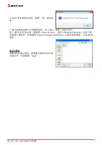
28 | 第三章 : UEFI BIOS 和軟體 6. BIOS 更新過程结束後,點擊”OK”重新啟 動。 7. 當系統啟動並顯示全螢幕標誌時,按 <DEL> 鍵進入 BIOS 設定。 進入 BIOS 設定程式後,請選擇 <Save & Exit>,使用 <Restore Defaults> 功能下載 系統優化預設值,然後選擇 <Save Changes and Reset> 以重新啟動電腦。 完成 BIOS 更新。 BIOS 備份 點擊 BIOS 備份按鈕,選擇備份檔案內的合適 目錄命名,然後點擊”Save”。
Page 177 - BIOScreen 工具
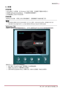
第三章 : UEFI BIOS 和軟體 | 29 B660GTA 3�3 軟體 安裝軟體 1. 將光碟放入光碟機,若 Autorun 功能已啓動,則會顯示驅動安裝程式。 2. 選擇 Software Installation,然後點擊各軟體圖示。 3. 根據螢幕上的指令完成安裝。 啓動軟體 安裝程式完成後,桌面上將出現軟體圖示。請雙擊圖示啓動軟體工具。 » 所有軟體的相關訊息和内容若有變更,恕不另行通知。為使系統性能更佳,軟體會不斷升級。 » 下面的圖片和訊息僅供參考,此主板的實際訊息和設定可能與手册略有差異。 BIOScreen 工具 此實用工具可以將開機畫面個性化。您可以選擇 BMP 格式...
Page 178 - RACING GT EVO Utility
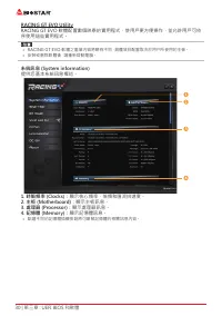
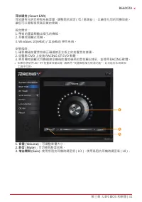
30 | 第三章 : UEFI BIOS 和軟體 RACING GT EVO Utility RACING GT EVO 軟體配置數個映泰的實用程式,使用戶更方便操作,並允許用戶可依 序使用這些實用程式。 » RACING GT EVO 軟體之選單内容將略有不同,具體項目配置取决於用户所使用的主板。 » 安裝或删除軟體後,請重新啓動電腦。 系統訊息 (System information) 提供您基本系統訊息概述。 1� 時脈頻率 (Clocks): 顯示核心頻率、倍頻和匯流排速度。 2� 主板 (Motherboard): 顯示主板訊息。 3� 處理器 (Processor): 顯示處理器訊...
Page 183 - � PWM/Temperature Panel:; DC
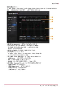
第三章 : UEFI BIOS 和軟體 | 35 B660GTA 智能風扇 (A�I Fan) A.I FAN 實用程式允許使用者具有更多調整風扇操作模式的智能性,並自動檢測不同的 溫度,使風扇以規定的速度運行,以獲得最佳的冷卻效能。 1� 溫度 (Temperature): 顯示當前 CPU 和系統溫度。 2� CPU FAN/ CPU OPT RPM & SYSTEM1/2/3 RPM: 單擊按鈕提供您設定 CPU 風扇、系統風扇的狀態值。 » 顯示項目,請以實際主板為準。 3� 預設 (Default): 恢復預設您單個項目的更改值。 4� PWM/Temperature Pan...
Page 184 - � 風扇轉速:; 顯示當前風扇速度。
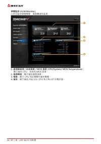
36 | 第三章 : UEFI BIOS 和軟體 硬體監測 (H/W Monitor) 允許您監控硬體電壓,風扇轉速和溫度。 1� 處理器溫度 / 系統溫度 / MOS 溫度 (CPU/System/ MOS Temperature): 顯示當前 CPU,系統和 MOS 溫度。 2� 風扇轉速: 顯示當前風扇速度。 3� 電壓: 顯示 CPU 和記憶體的當前電壓。 4� 當前: 顯示當前 PSU 12V ,CPU 和 CPU GT 的電流值。
Page 185 - � Default:
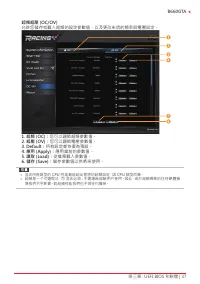
第三章 : UEFI BIOS 和軟體 | 37 B660GTA 超頻超壓 (OC/OV) 允許您儲存或載入超頻的設定參數值,以及更改系统的頻率與電壓設定。 1� 超頻 (OC): 您可以調節超頻參數值。 2� 超壓 (OV): 您可以調節電壓參數值。 3� Default: 所有設定都恢復為預設。 4� 應用 (Apply): 應用當前的參數值。 5� 讀取 (Load): 從檔案載入參數值。 6� 儲存 (Save): 儲存參數值以供將來使用。 » 並非所有類型的 CPU 性能都能超出理想的超頻設定,因 CPU 類型而異。 » 超頻是一个可選程式,而 並非必須 ; 不建議無經驗用户使用。因...
Page 186 - 此選單顯示 Racing GT EVO Utility 版本訊息。
38 | 第三章 : UEFI BIOS 和軟體 關於 (About) 此選單顯示 Racing GT EVO Utility 版本訊息。
Page 187 - 驅動程式安裝注意事項; A� 驅動程式安裝
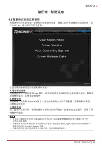
第四章 : 幫助訊息 | 39 B660GTA 第四章 : 幫助訊息 4�1 驅動程式安裝注意事項 為獲得更好的系統性能,在操作系統安裝完成後,請插入您的系統驅動光碟並安裝。插 入 DVD 後,將出現如下所示畫面。 此設定將自動檢測您的主板和操作系統。 A� 驅動程式安裝 安裝驅動程式,請點擊 Driver 圖示。設定指南將自動檢測您的主板和操作系統。點擊各 設備驅動程式,以開始安裝程序。 B� 軟體安裝 安裝軟體,請點擊 Software 圖示。設定指南將列出系統可用軟體,點擊各軟體名稱, 以開始安裝程序。 C� 使用手册 除了書本形式的手册,我們也提供光碟形式的使用指南。點擊 Manual...
Page 188 - AMI BIOS 提示音代碼; 啓動區塊模組提示音代碼; BIOS 開機自檢提示音代碼; 提示音次數; AMI BIOS 開機自檢代碼; 代碼 含義
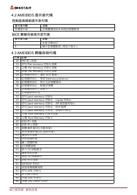
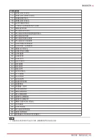
40 | 第四章 : 幫助訊息 4�2 AMI BIOS 提示音代碼 啓動區塊模組提示音代碼 提示音次數 含義 持續提示音 記憶體錯誤或未找到記憶體模塊 BIOS 開機自檢提示音代碼 提示音次數 含義 1 系統引導成功 8 顯示記憶體錯誤 ( 視訊介面卡 ) 4�3 AMI BIOS 開機自檢代碼 代碼 含義 10 PEI 核心啓動11 CPU Pre-memory 初始化啓動15 北橋 Pre-memory 初始化啓動19 南橋 Pre-memory 初始化啓動2B 記憶體初始化,讀取 SPD 數據 2C 記憶體初始化,檢測 Memory presence 2D 記憶體初始化,程式化記憶體資...
Page 190 - 問題解答; 問題
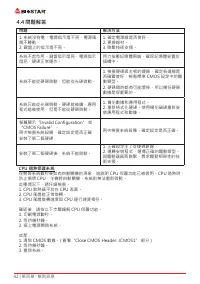
42 | 第四章 : 幫助訊息 4�4 問題解答 問題 解决方法 1. 系統沒有電,電源指示燈不亮,電源風 扇不轉動。 2. 鍵盤上的指示燈不亮。 1. 確定電源線是否接好。 2. 更換線材。 3. 聯繫技術支援。 系統不起作用。鍵盤指示燈亮,電源指示 燈亮,硬碟正常運作。 用力按壓記憶體兩端,確保記憶體安置於 插槽中。 系統不能從硬碟啓動,但能從光碟啓動。 1. 檢查硬碟與主板的連線,確定各連線是 否確實接好,檢查標準 CMOS 設定中的驅 動類型。 2. 硬碟隨時都有可能壞掉,所以備份硬碟 數據是很重要的。 系統只能從光碟啓動。硬碟能被讀,應用 程式能被使用,但是不能從硬碟啓動。 1. 備...
Page 191 - RAID 功能; RAID 定義; 性能及優點
第四章 : 幫助訊息 | 43 B660GTA 4�5 RAID 功能 RAID 定義 在 RAID 0 中,同一時間內向多塊磁碟寫入數據,通過 把數據分成多個數據塊(Block)並執行寫入 / 讀出多個 磁碟以提高磁碟的速度分散到所有的硬碟中同時進 行讀寫,在整個磁碟陣列建立過程中,以系統環境為基 礎,指數的大小決定了每塊磁盤的容量。此技術可減少 整個磁碟的存取時間和提供高的頻寬。 性能及優點 • 驅動器 : 最少 2 塊硬碟,最多達 6 塊或 8 塊,取決於平台。 • 使用 : 使用 RAID 0 來提高磁碟的性能和流通量,但没有冗餘或錯誤修復能力。 • 優點 : 增加磁碟的容量。 • 缺...
Page 193 - 英特爾
第四章 : 幫助訊息 | 45 B660GTA 4�6 英特爾 ® Optane 技術 ( 由 3D XPoint 記憶體供電 ) 透過英特爾 ® Optane ™技術,您可以完全釋放處理器的威力,而不只是運用一小部分 而已。要突破這個瓶頸,則需要更佳的儲存記憶體,具備快速、價格實惠、非揮發性的 特色。 英特爾 ® Optane 技術具有為大數據、高效能運算、虛擬化、儲存、雲端、遊戲 與其他多種應用帶來革命性改變的潛力。 性能及優點 : • 大容量記憶體數據庫 • 快速系統恢復 • 低延遲 • 高耐力 英特爾 ® Optane 技術的需求簡介: • 英特爾 ® Optane 記憶體或儲存。 •...
Page 194 - 6 | 附錄:產品中有毒有害物質或元素的名稱及含量; 附錄:產品中有毒有害物質或元素的名稱及含量
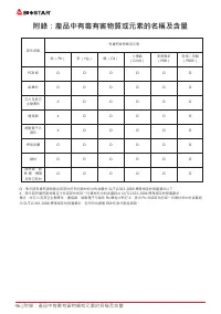
46 | 附錄:產品中有毒有害物質或元素的名稱及含量 附錄:產品中有毒有害物質或元素的名稱及含量 部件名稱 有毒有害物質或元素 鉛 (Pb) 汞 (Hg) 鎘 (Cd) 六價鉻 (Cr(VI)) 多溴聯苯 (PBB) 多溴二苯醚 (PBDE) PCB 板 O O O O O O 結構件 O O O O O O 芯片及其它 主動零件 X O O O O O 連接器 X O O O O O 被動電子元 器件 X O O O O O 焊接金屬 O O O O O O 線材 O O O O O O 助焊劑,散 熱 膏,標簽 及其它耗材 O O O O O O O:表示該有毒有害物質在該部件所有均質材料...