Page 2 - | Table Of Contents; Table Of Contents; FCC Information and Copyright
2 | Table Of Contents Table Of Contents FCC Information and Copyright ������������������������������������������������������������������������������� 1 Chapter 1: Introduction ������������������������������������������������������������������������������������������� 3 1.1 Before You Start ............
Page 3 - Chapter 1: Introduction; Before You Start
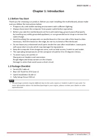
Chapter 1: Introduction | 3 B550T-SILVER Chapter 1: Introduction 1�1 Before You Start Thank you for choosing our product. Before you start installing the motherboard, please make sure you follow the instructions below: • Prepare a dry and stable working environment with sufficient lighting. • Alwa...
Page 4 - Specifications
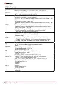
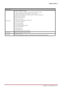
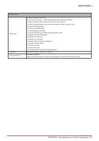
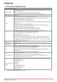
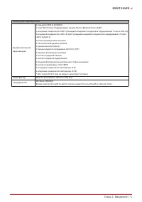
4 | Chapter 1: Introduction 1�3 Specifications Specifications CPU Support Socket AM4 support AMD® Ryzen™ 3rd Gen (Matisse/ Renoir) and Ryzen™ 4th Gen(Vermeer/ Future) processorsSupport for future AMD Ryzen processors with BIOS update* Please refer to www.biostar.com.tw for CPU support list. Chipset ...
Page 6 - Rear Panel Connectors
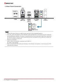
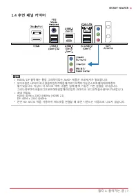
6 | Chapter 1: Introduction 1.4 Rear Panel Connectors Note » HDMI / DP output require an AMD® family processor with intedrated graphics. » Since the audio chip supports High Definition Audio Specification, the function of each audio jack can be defined by software. The input / output function of...
Page 7 - Motherboard Layout; Top View
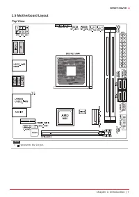
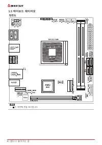
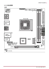
Chapter 1: Introduction | 7 B550T-SILVER 1.5 Motherboard Layout Top View Note » represents the 1st pin.
Page 8 - Back View
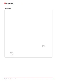
8 | Chapter 1: Introduction Back View LAN Super I/O
Page 9 - Chapter 2: Hardware installation; Step 1: Locate the CPU socket on the motherboard
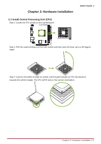
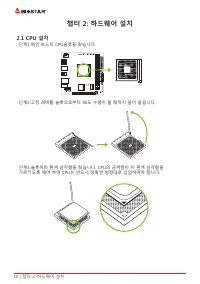
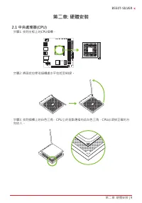
Chapter 2: Hardware installation | 9 B550T-SILVER Chapter 2: Hardware installation 2.1 Install Central Processing Unit (CPU) Step 1: Locate the CPU socket on the motherboard Step 2: Pull the socket locking out from the socket and then raise the lever up to a 90-degree angel. Step 3: Look for the whi...
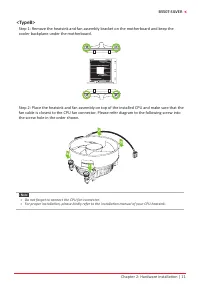
Page 10 - the retention frame, and then press down the locker until it stops.
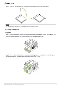
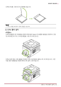
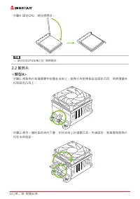
10 | Chapter 2: Hardware installation Step 4: Hold the CPU down firmly, and then close the lever to locked the position Note » Please turn off the Power Supply before remove the CPU socket. 2.2 Install a Heatsink<TypeA> Step 1: Place the heatsink and fan assembly onto the retention frame. Ma...
Page 12 - Connect Cooling Fans; may be different according to the fan manufacturer.
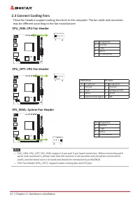
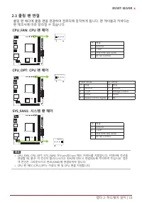
12 | Chapter 2: Hardware installation 2.3 Connect Cooling Fans These fan headers support cooling-fans built in the computer. The fan cable and connector may be different according to the fan manufacturer. CPU_FAN: CPU Fan Header Pin Assignment1 Ground 2 +12V 3 Sense 4 AI Fan Control CPU_OPT: CPU Fan...
Page 13 - Install System Memory; DDR4 Modules; such that the notch on the DIMM matches the break on the slot.
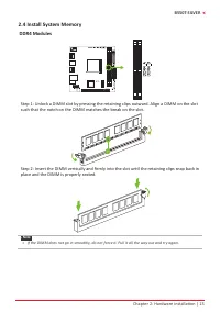
Chapter 2: Hardware installation | 13 B550T-SILVER 2.4 Install System Memory DDR4 Modules Step 1: Unlock a DIMM slot by pressing the retaining clips outward. Align a DIMM on the slot such that the notch on the DIMM matches the break on the slot. Step 2: Insert the DIMM vertically and firmly into the...
Page 14 - Memory Capacity; DIMM Socket Location DDR4 Module; Dual Channel Memory Installation; Dual Channel Status; please place the screw and hex pillar to correct position.
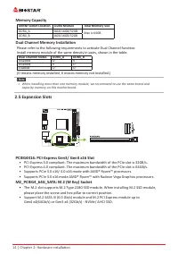
14 | Chapter 2: Hardware installation Memory Capacity DIMM Socket Location DDR4 Module Total Memory Size DDR4_A 8GB/16GB/32GB Max is 64GB. DDR4_B 8GB/16GB/32GB Dual Channel Memory Installation Please refer to the following requirements to activate Dual Channel function: Install memory module of the ...
Page 15 - Install an Expansion Card; You can install your expansion card by following steps:
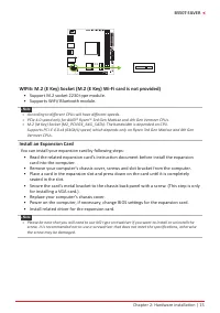
Chapter 2: Hardware installation | 15 B550T-SILVER WIFI6: M.2 (E Key) Socket (M.2 (E Key) Wi-Fi card is not provided) • Support M.2 socket 2230 type module. • Supports WiFi/ Bluetooth module. Note » According to different CPUs will have different speeds. » PCIe 4.0 speed only for AMD® Ryzen™ 3...
Page 16 - JCMOS1: Clear CMOS Jumper; follow the procedures to avoid damaging the motherboard.; Clear CMOS Procedures:; Load Optimal Defaults and save settings in CMOS.
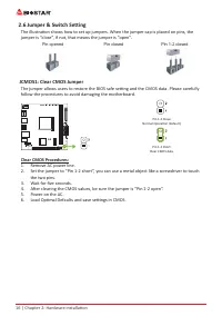
16 | Chapter 2: Hardware installation 2.6 Jumper & Switch Setting The illustration shows how to set up jumpers. When the jumper cap is placed on pins, the jumper is “close”, if not, that means the jumper is “open”. Pin opened Pin closed Pin 1-2 closed JCMOS1: Clear CMOS Jumper The jumper allows ...
Page 17 - ATX: ATX Power Source Connector
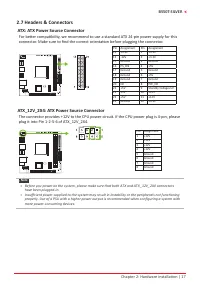
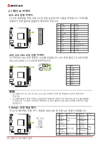
Chapter 2: Hardware installation | 17 B550T-SILVER 2.7 Headers & Connectors ATX: ATX Power Source Connector For better compatibility, we recommend to use a standard ATX 24-pin power supply for this connector. Make sure to find the correct orientation before plugging the connector. Pin Assignment...
Page 18 - to connect the PC case’s front panel switch functions.; SPKR: Chassis Speaker Header; Please connect the chassis speaker to this header.
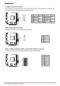
18 | Chapter 2: Hardware installation F_PANEL: Front Panel Header This connector includes Power-on, Reset, HDD LED and Power LED connections. It allows user to connect the PC case’s front panel switch functions. Pin Assignment Function Pin Assignment Function 1 HDD LED(+) HDD LED 2 Power LED (+) Pow...
Page 20 - LEDs; detail software setting.
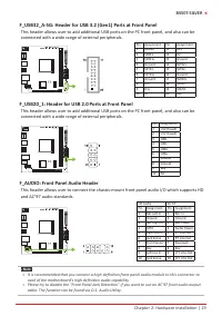
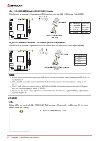
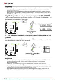
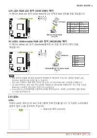
20 | Chapter 2: Hardware installation 12V_LED: RGB LED Device (5050 SMD) Header This header providers 12V power and RGB control pins for RGB LED Device (5050 SMD). Pin Cable Color Assignment1 12V (Black) VCC12 2 G (Green) LED_GREEN 3 R (Red) LED_RED 4 B (Blue) LED_BLUE 5V_LED1: Addressable RGB LED D...
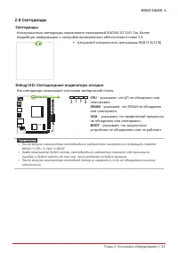
Page 21 - Debug LED: Debug LED Indicators; This LEDs indicate the status of the motherboard.; CPU; - indicates CPU is not detected or fail.; DRAM; - indicates DRAM is not detected or fail.; VGA; - indicates GPU is not detected or fail.; BOOT; - indicates booting device is not detected
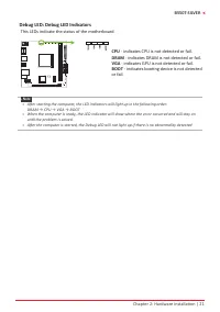
Chapter 2: Hardware installation | 21 B550T-SILVER Debug LED: Debug LED Indicators This LEDs indicate the status of the motherboard. CPU - indicates CPU is not detected or fail. DRAM - indicates DRAM is not detected or fail. VGA - indicates GPU is not detected or fail. BOOT - indicates booting devic...
Page 22 - The BIOS can be updated using either of the following utilities:; Updating BIOS with BIOSTAR BIO-Flasher
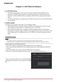
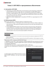
22 | Chapter 3: UEFI BIOS & Software Chapter 3: UEFI BIOS & Software 3.1 UEFI BIOS Setup • The BIOS Setup program can be used to view and change the BIOS settings for the computer. The BIOS Setup program is accessed by pressing the <DEL> key after the Power-On Self-Test (POST) memory ...
Page 23 - BIOS Update Utility (through the Internet)
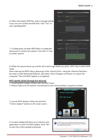
Chapter 3: UEFI BIOS & Software | 23 B550T-SILVER 6. Select the proper BIOS file, and a message asking if you are sure to flash the BIOS file. Click “Yes” to start updating BIOS. 7. A dialog pops out after BIOS flash is completed, asking you to restart the system. Press the <Y> key to rest...
Page 24 - BIOS Update Utility (through a BIOS file)
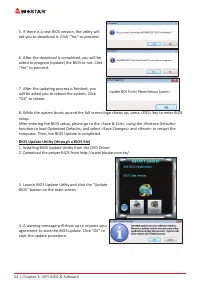
24 | Chapter 3: UEFI BIOS & Software 5. If there is a new BIOS version, the utility will ask you to download it. Click “Yes” to proceed. 6. After the download is completed, you will be asked to program (update) the BIOS or not. Click “Yes” to proceed. 7. After the updating process is finished, y...
Page 25 - Backup BIOS
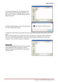
Chapter 3: UEFI BIOS & Software | 25 B550T-SILVER 5. Choose the location for your BIOS file in the system. Please select the proper BIOS file, and then click on “Open”. It will take several minutes, please be patient. 6. After the BIOS Update process is finished, click on “OK” to reboot the syst...
Page 26 - Installing Software; Follow the on-screen instructions to complete the installation.; Launching Software; BIOScreen Utility; logo so as to customize your computer.
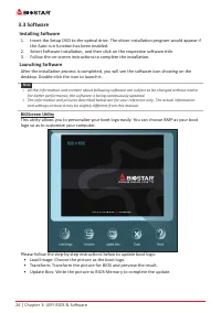
26 | Chapter 3: UEFI BIOS & Software 3.3 Software Installing Software 1. Insert the Setup DVD to the optical drive. The driver installation program would appear if the Auto-run function has been enabled. 2. Select Software Installation, and then click on the respective software title. 3. Follow ...
Page 27 - RACING GT EVO; System Information; Shows core speed, multiplier and bus speed.
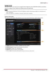
Chapter 3: UEFI BIOS & Software | 27 B550T-SILVER RACING GT EVO RACING GT EVO is an easy-to-use program that integrates several BIOSTAR utilities and allows users to configure these utilities simultaneously and seamlessly. Note » Menu contents of RACING GT EVO will be different slightly, depen...
Page 28 - SmartEAR
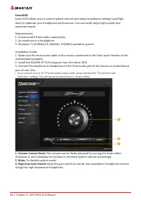
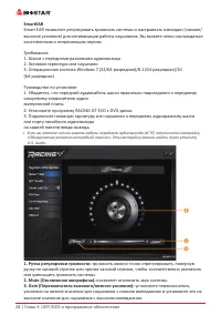
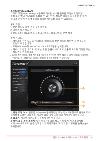
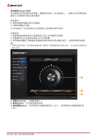
28 | Chapter 3: UEFI BIOS & Software SmartEAR Smart EAR allows you to control system volume and adjust impedance setting (Low/High Gain) to optimize your headphone performance. You can easily enjoy high-quality and awesome sound. Requirements: 1. A chassis with front audio output jacks 2. An ear...
Page 29 - GT Touch; program in Windows environment.
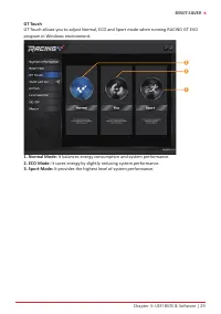
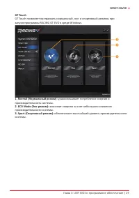
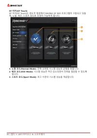
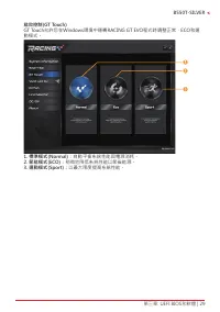
Chapter 3: UEFI BIOS & Software | 29 B550T-SILVER GT Touch GT Touch allows you to adjust Normal, ECO and Sport mode when running RACING GT EVO program in Windows environment. 1. Normal Mode: It balances energy consumption and system performance. 2. ECO Mode: It saves energy by slightly reducing ...
Page 30 - Vivid LED DJ
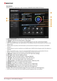
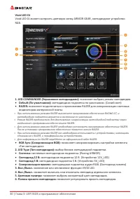
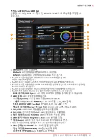
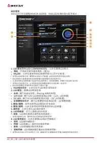
30 | Chapter 3: UEFI BIOS & Software Vivid LED DJ Vivid LED DJ can adjust your color scheme of ARMOR GEAR, RGB LED Device. 1. LED COMMANDER: Allows you to select the LED mode. • Default : Default LED illuminations. (Blue light) • RAZER : Allows you to connect to the RAZER app to sync the mothe...
Page 32 - A�I Fan
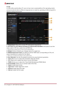
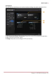
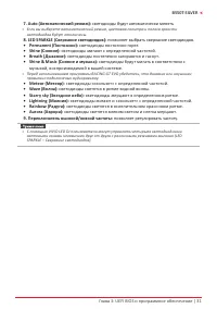
32 | Chapter 3: UEFI BIOS & Software A�I Fan A.I FAN utility smartly allows PC users to have more customizability of fan operating modes and automatically detects different temperatures to make fan operating at defined speed for optimal cooling performance. 1. Temperature: Shows the current CPU ...
Page 35 - About
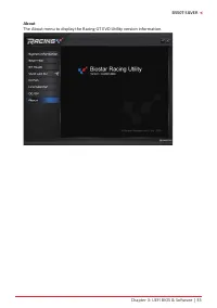
Chapter 3: UEFI BIOS & Software | 35 B550T-SILVER About The About menu to display the Racing GT EVO Utility version information.
Page 36 - Chapter 4: Useful help; Driver Installation; You will see the following window after you insert the DVD; A. Driver Installation; installation program.; B. Software Installation; Manual icon to browse for available manual.
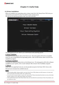
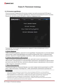
36 | Chapter 4: Useful help Chapter 4: Useful help 4.1 Driver Installation After you installed your operating system, please insert the Fully Setup Driver DVD into your optical drive and install the driver for better system performance. You will see the following window after you insert the DVD The ...
Page 37 - AMI BIOS Beep Code; Boot Block Beep Codes; POST BIOS Beep Codes; Number of Beeps; AMI BIOS post code; Code Description
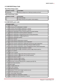
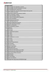
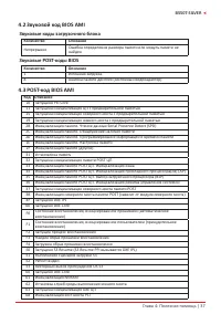
Chapter 4: Useful help | 37 B550T-SILVER 4.2 AMI BIOS Beep Code Boot Block Beep Codes Number of Beeps Description Continuing Memory sizing error or Memory module not found POST BIOS Beep Codes Number of Beeps Description 1 Success booting. 8 Display memory error (system video adapter) 4.3 AMI BIOS p...
Page 39 - Troubleshooting; Probable; CPU Overheated
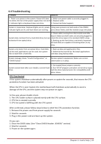
Chapter 4: Useful help | 39 B550T-SILVER 4.4 Troubleshooting Probable Solution 1. There is no power in the system. Power LED does not shine; the fan of the power supply does not work 2. Indicator light on keyboard does not shine. 1. Make sure power cable is securely plugged in. 2. Replace cable. 3. ...
Page 40 - RAID Functions; RAID Definitions; Features and Benefits
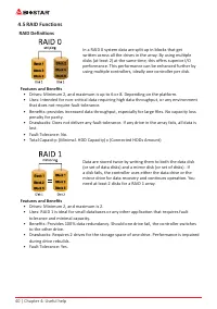
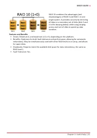
40 | Chapter 4: Useful help 4.5 RAID Functions RAID Definitions In a RAID 0 system data are split up in blocks that get written across all the drives in the array. By using multiple disks (at least 2) at the same time, this offers superior I/O performance. This performance can be enhanced further by...
Page 42 - 2 | APPENDIX I: Specifications in Other Languages; APPENDIX I: Specifications in Other Languages; Arabic
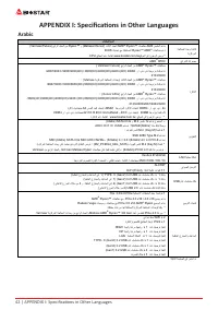
42 | APPENDIX I: Specifications in Other Languages APPENDIX I: Specifications in Other Languages Arabic تﺎﻔﺻاﻮﻤﻟا ﺔﺠﻟﺎﻌﻤﻟا ةﺪﺣو ةﺪﻋﺎﻗ ﺔﻳﺰآﺮﻤﻟا (Vermeer/Future) ﻊﺑاﺮﻟا ﻞﻴﺠﻟا ﻦﻣ Ryzen™ و (Matisse/ Renoir) ﺚﻟﺎﺜﻟا ﻞﻴﺠﻟا AMD ® Ryzen™ تﺎﺠﻟﺎﻌﻣ AM4 ﺲﺒﻘﻤﻟا ﻢﻋﺪﻳ .BIOS ﺚﻳﺪﺤﺗ ﻊﻣ ﺔﻴﻠﺒﻘﺘﺴﻤﻟا Ryzen™ AMD ® تﺎﺠﻟﺎﻌﻣ ...
Page 43 - APPENDIX I: Specifications in Other Languages | 43
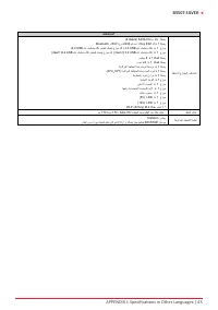
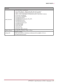
APPENDIX I: Specifications in Other Languages | 43 B550T-SILVER تﺎﻔﺻاﻮﻤﻟا ﺔﻴﻠﺧاﺪﻟا جرﺎﺨﻤﻟاو ﻞﺧاﺪﻤﻟا ﺔﻠﺻو 4x ﺎﺗﺎﺳ SATA III (6.0Gb/s) ﺔﻠﺻو x 1 2 . M ) Key E : ( Wi-Fi عﻮﻧ 2230 ﻢﻋﺪ����ﺗ و Bluetooth عزﻮﻣ 1 x مﺎﻋ ﻞﺴﻠﺴﺘﻣ ﻞﻗﺎﻧ USB 2.0 ) مﺎﻋ ﻞﺴﻠﺴﺘﻣ ﻞﻗﺎﻧ ﻦﻴﺘﺤﺘﻓ ﻞﻤﺤﺘﻳ عزﻮﻣ ﻞآ USB 2.0 ( عزﻮﻣ 1 x مﺎﻋ ﻞﺴﻠﺴﺘﻣ ﻞﻗﺎ...
Page 44 - 4 | APPENDIX I: Specifications in Other Languages; German
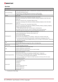
44 | APPENDIX I: Specifications in Other Languages German Spezifikationen CPU-Unterstützung Sockel AM4 unterstützt AMD® Ryzen ™ Prozessoren der 3. Generation (Matisse/ Renoir) und Ryzen™ 4. Generation (Vermeer/ Future)Unterstützung für zukünftige AMD Ryzen-Prozessoren mit BIOS-Update* Bitte konsulti...
Page 45 - APPENDIX I: Specifications in Other Languages | 45
APPENDIX I: Specifications in Other Languages | 45 B550T-SILVER Spezifikationen Interne I/Os 4x SATA III 6.0Gb/s-Verbinung1x M.2 (E Key) Steckdose : Unterstützt 2230 Art Wi-Fi & Bluetooth Modul 1x USB 2.0-Header (jeder Header unterstützt 2 USB 2.0-Ports)1x USB 3.2 (Gen1)-Header (jeder Header unt...
Page 46 - 6 | APPENDIX I: Specifications in Other Languages; Spanish
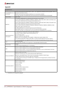
46 | APPENDIX I: Specifications in Other Languages Spanish Especificaciones Compatibilidad con el procesador Socket AM4 admite procesadores AMD® Ryzen ™ de 3.ª generación (Matisse / Renoir) y Ryzen ™ de 4.ª generación (Vermeer/ Future)Soporte para futuros procesadores AMD Ryzen con actualización del...
Page 47 - APPENDIX I: Specifications in Other Languages | 47
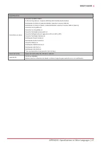
APPENDIX I: Specifications in Other Languages | 47 B550T-SILVER Especificaciones Conectores en placa Conector 4x SATA III 6Gb’s1x M.2 (E Key) Ranura : Soporta 2230 tipo Wi-Fi & Bluetooth moduleDistribuidor 1x USB 2.0 (cada distribuidor soporta 2 ranuras USB 2.0)Distribuidor 1x USB 3.2 (Gen1) -(c...
Page 48 - 8 | APPENDIX I: Specifications in Other Languages; Thai
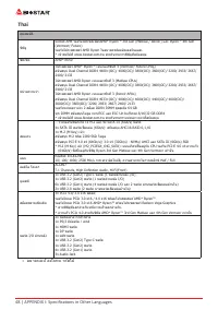
48 | APPENDIX I: Specifications in Other Languages Thai คุณสมบัติ ซีพียู Socket AM4 รองรับโปรเซสเซอร์AMD ® Ryzen™ 3rd Gen (Matisse / Renoir) และ Ryzen™ 4th Gen (Vermeer/ Future) รองรับโปรเซสเซอร์ AMD Ryzen ในอนาคตพร้อมอัพเดตไบออส.* เข้าชมได้ที่ www.biostar.com.tw สำาหรับรายการซีพียูที่สนับสนุน ชิพเซ...
Page 49 - APPENDIX I: Specifications in Other Languages | 49
APPENDIX I: Specifications in Other Languages | 49 B550T-SILVER คุณสมบัติ พอร์ต I/O ด้านใน 4x SATA III (6Gb/s) พอร์ตเชื่อมต่อ1x M.2 (E Key) ซ็อกเก็ต : สนับสนุน ชนิด 2230 โมดูล Wi-Fi และบลูทู ธ1x USB 2.0 พอร์ตเชื่อมต่อ (หัวเชื่อมต่อทุกตัวรองรับ 2 พอร์ต USB 2.0)1x USB 3.2 (Gen1) พอร์ตเชื่อมต่อ (หัวเชื...
Page 50 - 0 | APPENDIX I: Specifications in Other Languages; Japan
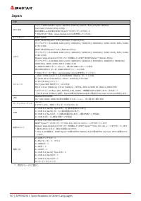
50 | APPENDIX I: Specifications in Other Languages Japan 仕様 CPU 対応 ソケットAM4 はAMD ® Ryzen™第3世代 (Matisse/ Renoir) および Ryzen™第4世代 (Vermeer/ Future) CPUs に対応BIOS更新による将来のAMD ® Ryzen™プロセッサーのサポート * 対応CPUの一覧は、www.biostar.com.twを参照してください チップセット AMD® B550 メモリ AMD ® 第4世代Ryzen™ CPU (Vermeer/ Future CPUs): デュアルチャ...
Page 51 - APPENDIX I: Specifications in Other Languages | 51
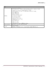
APPENDIX I: Specifications in Other Languages | 51 B550T-SILVER 仕様 内部 I/O 4x SATA IIIコネクタ(6Gb/s)1x M.2 (E Key)コネクタ:2230タイプのWi-FiおよびBluetoothモジュールをサポートに対応1x USB 2.0ヘッダー(各ヘッダーは2台のUSB 2.0ポートに対応)1x USB 3.2 (Gen1)ヘッダー(各ヘッダーは2台のUSB 3.2 (Gen1)ポートに対応)1x 8ピン電源コネクタ1x 24ピン電源コネクタ1x CPUファンコネクタ1x CPU水冷コネクタ(CPU_OP...
Page 53 - Информация FCC и авторское право; без обязательства заранее уведомлять какую-либо сторону.
Информация FCC и авторское право Это оборудование было протестировано и признано соответствующим ограничениям для цифровых устройств класса B в соответствии с частью 15 правил Федеральной комиссии по связи США (FCC). Эти ограничения разработаны для обеспечения разумной защиты от вредных помех при ус...
Page 54 - Содержание; Информация FCC и авторское право ��������������������������������������������������������������������
2 | Содержание Содержание Информация FCC и авторское право �������������������������������������������������������������������� 1 Глава 1: Введение �������������������������������������������������������������������������������������������������� 3 1.1 Перед началом ....................................
Page 56 - Технические характеристики
4 | Глава 1: Введение 1�3 Технические характеристики Технические характеристики Поддержка ЦП Сокет AM4 поддерживает процессоры AMD® 3-го поколения (Matisse/ Renoir)/ 4-го поколения Ryzen™ (Vermeer/ Future)Поддержка будущих процессоров AMD Ryzen с обновлением BIOS* Перечень поддержки центрального про...
Page 58 - Разъемы задней панели
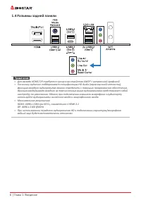
6 | Глава 1: Введение 1�4 Разъемы задней панели » » Для выхода HDMI/ DP требуется процессор семейства AMD® с встроенной графикой. » » Поскольку аудиочип поддерживает спецификацию HD Audio (звука высокой четкости), функцию каждого аудиоразъема можно определить с помощью программного обеспечения. ...
Page 59 - �5 Компоновка материнской платы; Вид сверху
Глава 1: Введение | 7 B550T-SILVER 1�5 Компоновка материнской платы Вид сверху » » представляет собой 1-й контакт.
Page 60 - Вид сзади
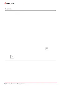
8 | Глава 2: Установка оборудования Вид сзади LAN Super I/O
Page 61 - Глава 2: Установка оборудования; �1 Установка центрального процессора (ЦП); Шаг 1: Найдите сокет ЦП на материнской плате.
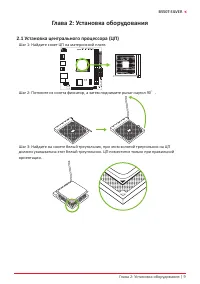
Глава 2: Установка оборудования | 9 B550T-SILVER Глава 2: Установка оборудования 2�1 Установка центрального процессора (ЦП) Шаг 1: Найдите сокет ЦП на материнской плате. Шаг 2: Потяните из сокета фиксатор, а затем поднимите рычаг наугол 90 ゜. Шаг 3: Найдите на сокете белый треугольник, при этом золо...
Page 62 - Шаг 4: Крепко удерживая ЦП, опустите рычаг в положение фиксации.
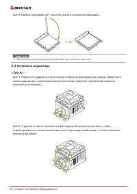
10 | Глава 2: Установка оборудования Шаг 4: Крепко удерживая ЦП, опустите рычаг в положение фиксации. » » Выключите электропитание перед тем, как вынуть сокет ЦП. 2�2 Установка радиатора<Тип А> Шаг 1: Поместите радиатор и вентилятор в сборе на фиксирующую рамку. Совместите зажим радиатора с м...
Page 63 - установки винтов в отверстия на следующей схеме.
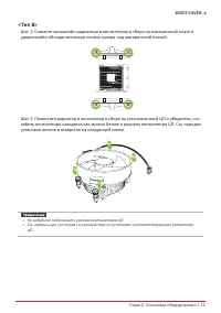
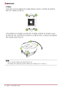
Глава 2: Установка оборудования | 11 B550T-SILVER <Тип В> Шаг 1: Снимите кронштейн радиатора и вентилятора в сборе на материнской плате и удерживайте объединительную панель кулера под материнской платой. Шаг 2: Поместите радиатор и вентилятор в сборе на установленный ЦП и убедитесь, что кабель...
Page 64 - �3 Подключение охлаждающих вентиляторов; от производителя вентилятора.; CPU_FAN: Штыревой соединитель вентилятора ЦП
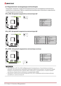
12 | Глава 2: Установка оборудования 2�3 Подключение охлаждающих вентиляторов Следующие штыревые соединители предназначены для охлаждающих вентиляторов, встроенных в компьютер. Кабель и разъем вентилятора могут отличаться в зависимости от производителя вентилятора. CPU_FAN: Штыревой соединитель вент...
Page 65 - �4 Установка системной памяти; Модули DDR4; защелкнулисьи модуль DIMM установился должным образом.
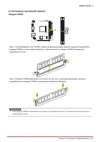
Глава 2: Установка оборудования | 13 B550T-SILVER 2�4 Установка системной памяти Модули DDR4 Шаг 1: Разблокируйте слот DIMM, нажав на фиксирующие зажимы наружу. Выровняйте модуль DIMM в слоте таким образом, чтобы выемка на модуле DIMM совпадала с разрывом в слоте. Шаг 2: Вставьте DIMM вертикально пл...
Page 66 - Емкость памяти; Расположение; Установка двухканальной памяти; Статус двойного; �5 Слоты расширения; M.2установите винт и шестигранную стойку в правильное положение.
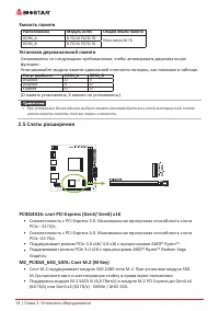
14 | Глава 2: Установка оборудования Емкость памяти Расположение Модуль DDR4 Общий объем памяти DDR4_A 8 ГБ/16 ГБ/32 ГБ Максимум 64 ГБ. DDR4_B 8 ГБ/16 ГБ/32 ГБ Установка двухканальной памяти Ознакомьтесь со следующими требованиями, чтобы активировать двухканальную функцию: Устанавливайте модули памя...
Page 67 - Установка карты расширения
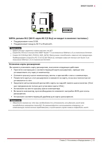
Глава 2: Установка оборудования | 15 B550T-SILVER WIFI6: разъем M�2 (Wi-Fi карта M�2 (E Key) не входит в комплект поставки�) • Поддерживает типа 2230. • Поддерживает модуль Wi-Fi и Bluetooth. » » Будут разные скорости в зависимости от ЦП. » » Скорость PCIe 4.0 только для AMD® Ryzen™ 3-го поколен...
Page 68 - �6 Установка перемычки и переключателя; JCMOS1: Перемычка очистки CMOS; Указания по очистке CMOS:; Отсоедините питание переменного тока.
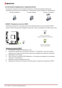
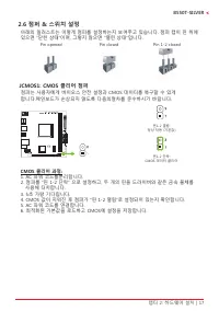
16 | Глава 2: Установка оборудования 2�6 Установка перемычки и переключателя На рисунке показано, как установить перемычки. Когда колпачковая перемычка помещена на контакты, она «замкнута», в противном случае перемычка «разомкнута». Контакт разомкнут Контакт замкнут Контакт 1-2 замкнут JCMOS1: Перем...
Page 69 - �7 Штыревые соединители и разъемы; ATX: разъем источника питания ATX; правильной ориентации.
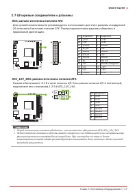
Глава 2: Установка оборудования | 17 B550T-SILVER 2�7 Штыревые соединители и разъемы ATX: разъем источника питания ATX Для лучшей совместимости рекомендуется использовать для этого разъема стандартный 24-контактный источник питания ATX. Перед подключением разъема убедитесь в правильной ориентации. P...
Page 70 - F_PANEL: штыревой соединитель передней панели; переключателя передней панели корпуса ПК; SPKR: штыревой соединитель динамика шасси; Подключите динамик шасси к этому штыревому соединителю.
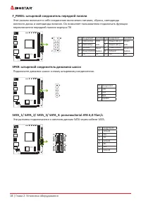
18 | Глава 2: Установка оборудования F_PANEL: штыревой соединитель передней панели Этот разъем включает в себя соединения включения питания, сброса, светодиода жесткого диска и светодиода питания. Он позволяет пользователю подключать функции переключателя передней панели корпуса ПК Pin Assignment Fu...
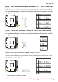
Page 71 - панели; периферийным устройствам.; F_AUDIO: штыревой соединитель аудио передней панели
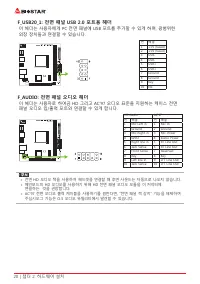
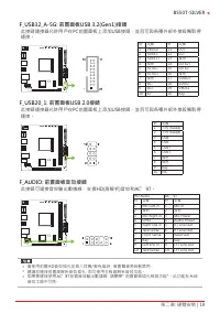
Глава 2: Установка оборудования | 19 B550T-SILVER F_USB32_A-5G: штыревой соединитель для портов USB 3�2 (Gen1) на передней панели Этот штыревой соединитель позволяет пользователю добавлять дополнительные порты USB на переднюю панель ПК, а также может быть подключен к самым разным внешним периферийны...
Page 73 - �8 Светодиоды; Светодиоды; Эти светодиоды показывают состояние материнской платы.; - указывает, что графический процессор; устройство не обнаружено или не работает.
Глава 2: Установка оборудования | 21 B550T-SILVER 2�8 Светодиоды Светодиоды Нижеуказанные светодиоды управляются программой RACING GT EVO. См. более подробную информацию о настройке программного обеспечения в главе 3.3. • Штыревой соединитель светодиода RGB (5 В/12 В) Debug LED: Светодиодные индика...
Page 74 - 2 | Глава 3: UEFI BIOS и программное обеспечение; Глава 3: UEFI BIOS и программное обеспечение; �1 Настройка UEFI BIOS
22 | Глава 3: UEFI BIOS и программное обеспечение Глава 3: UEFI BIOS и программное обеспечение 3�1 Настройка UEFI BIOS • Программа настройки BIOS может использоваться для просмотра и изменения настроек BIOS для компьютера. Доступ к программе настройки BIOS можно получить, нажав клавишу <DEL> ...
Page 75 - Глава 3: UEFI BIOS и программное обеспечение | 23
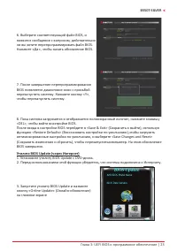
Глава 3: UEFI BIOS и программное обеспечение | 23 B550T-SILVER 6. Выберите соответствующий файл BIOS, и появится сообщение с вопросом, действительно ли вы хотите перепрограммировать файл BIOS. Нажмите «Да», чтобы начать обновление BIOS. 7. После завершения перепрограммирования BIOS появляется диалог...
Page 76 - 4 | Глава 3: UEFI BIOS и программное обеспечение
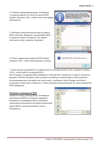
24 | Глава 3: UEFI BIOS и программное обеспечение 4. Откроется диалоговое окно с запросом вашего согласия на запуск BIOS Update. Нажмите «Да», чтобы начать процедуру онлайн-обновления. 5. Если есть новая версия BIOS, утилитапредложит вам загрузить ее. Нажмите «Да», чтобы продолжить. 6. После заверше...
Page 77 - Глава 3: UEFI BIOS и программное обеспечение | 25; Резервное копирование BIOS
Глава 3: UEFI BIOS и программное обеспечение | 25 B550T-SILVER 4. Появится предупреждающее сообщение с запросом вашего согласия на запуск BIOS Update. Нажмите «OK», чтобы начать процедуру обновления. 5. Выберите местоположение вашего файла BIOS в системе. Выберите нужный файл BIOS и нажмите «Open» (...
Page 78 - 6 | Глава 3: UEFI BIOS и программное обеспечение; �3 Программное обеспечение; Установка программного обеспечения; установки драйвера, если включена функция автозапуска.; Запуск программного обеспечения; Утилита BIOScreen
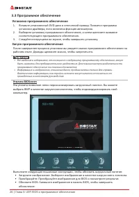
26 | Глава 3: UEFI BIOS и программное обеспечение 3�3 Программное обеспечение Установка программного обеспечения 1. Вставьте установочный DVD-диск в оптический привод. Появится программа установки драйвера, если включена функция автозапуска. 2. Выберите установку программного обеспечения, а затем ще...
Page 79 - Глава 3: UEFI BIOS и программное обеспечение | 27; Информация о системе
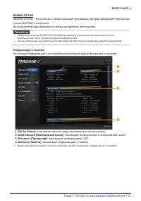
Глава 3: UEFI BIOS и программное обеспечение | 27 B550T-SILVER RACING GT EVO RACING GT EVO – это простая в использовании программа, которая объединяет несколько утилит BIOSTAR и позволяет пользователям одновременно и легко настраивать эти утилиты. » » Содержание меню RACING GT EVO будет немного отл...
Page 80 - 8 | Глава 3: UEFI BIOS и программное обеспечение
28 | Глава 3: UEFI BIOS и программное обеспечение SmartEAR Smart EAR позволяет регулировать громкость системы и настраивать импеданс (низкое/ высокое усиление) для оптимизации работы наушников. Вы можете легко наслаждаться качественным и потрясающим звуком. Требования: 1. Шасси с передними разъемами...
Page 81 - Глава 3: UEFI BIOS и программное обеспечение | 29
Глава 3: UEFI BIOS и программное обеспечение | 29 B550T-SILVER GT Touch GT Touch позволяет настраивать нормальный, эко- и спортивный режимы при запускепрограммы RACING GT EVO в среде Windows. 1� Normal (Нормальный режим): уравновешивает потребление энергии и производительность системы. 2� ECO Mode (...
Page 82 - 0 | Глава 3: UEFI BIOS и программное обеспечение; • Синхронизация памяти:
30 | Глава 3: UEFI BIOS и программное обеспечение Vivid LED DJ Vivid LED DJ может настроить цветовую схему ARMOR GEAR, светодиодное устройство RGB. 1� LED COMMANDER (Управление светодиодами): позволяет выбрать режим светодиодов. • Default (По умолчанию): светодиодная подсветка по умолчанию. (Синий ...
Page 83 - Глава 3: UEFI BIOS и программное обеспечение | 31
Глава 3: UEFI BIOS и программное обеспечение | 31 B550T-SILVER 7� Auto (Автоматический режим): светодиоды будут автоматически менять » » Если вы выберете автоматический режим, цветовая палитра и полоса яркости светодиодов будут отключены. 8� LED SPARKLE (Сверкание светодиодов): позволяет выбрать с...
Page 84 - 2 | Глава 3: UEFI BIOS и программное обеспечение
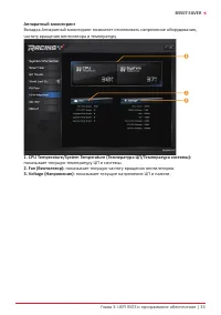
32 | Глава 3: UEFI BIOS и программное обеспечение A�I Fan Утилита A.I FAN позволяет пользователям ПК более гибко настраивать режимы работы вентилятора и автоматически определяет различные температуры, чтобы вентилятор работал с определенной скоростью для оптимального. 1� Temperature (Температура): п...
Page 85 - Глава 3: UEFI BIOS и программное обеспечение | 33; Аппаратный мониторинг; частоту вращения вентилятора и температуру.
Глава 3: UEFI BIOS и программное обеспечение | 33 B550T-SILVER Аппаратный мониторинг Вкладка Аппаратный мониторинг позволяет отслеживать напряжение оборудования, частоту вращения вентилятора и температуру. 1� CPU Temperature/System Temperature (Температура ЦП/Температура системы): показывает текущую...
Page 86 - 4 | Глава 3: UEFI BIOS и программное обеспечение
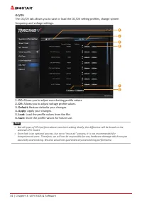
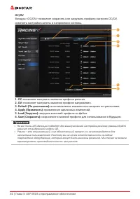
34 | Глава 3: UEFI BIOS и программное обеспечение OC/OV Вкладка <OC/OV> позволяет сохранять или загружать профили настроек OC/OV, изменять настройкичастоты и напряжения системы. 1� OC: позволяет настроить значения профиля разгона. 2� OV: позволяет настроить значения профиля напряжения. 3� Defa...
Page 87 - Глава 3: UEFI BIOS и программное обеспечение | 35; О программе
Глава 3: UEFI BIOS и программное обеспечение | 35 B550T-SILVER О программе Меню «О программе» для отображения информации о версии утилиты Racing GT EVO.
Page 88 - Глава 4: Полезная помощь; Установка драйвера; операционную систему.
36 | Глава 4: Полезная помощь Глава 4: Полезная помощь 4�1 Установка драйвера После установки операционной системы вставьте полный установочный DVD-диск в оптический привод и установите драйвер для повышения производительности системы. После того, как вы вставите DVD-диск, появится следующее окно. Р...
Page 89 - Звуковой код BIOS AMI; Звуковые коды загрузочного блока; Звуковые POST-коды BIOS; Количество; Код Описание
Глава 4: Полезная помощь | 37 B550T-SILVER 4�2 Звуковой код BIOS AMI Звуковые коды загрузочного блока Количество Описание Непрерывно Ошибка определения размера памяти или модуль памяти не найден Звуковые POST-коды BIOS Количество Описание 1 Успешная загрузка. 8 Ошибка памяти дисплея (системный видео...
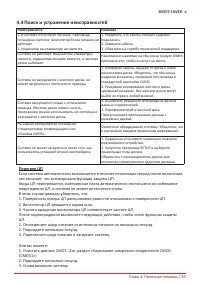
Page 91 - Поиск и устранение неисправностей; Неисправность; Перегрев ЦП; это означает, что активирована функция защиты ЦП.
Глава 4: Полезная помощь | 39 B550T-SILVER 4�4 Поиск и устранение неисправностей Неисправность Решение 1. В системе отсутствует питание. Светодиод питанияне светится; вентилятор блока питания не работает 2. Индикатор на клавиатуре не светится. 1. Убедитесь, что кабель питания надежно подключен. 2. З...
Page 92 - Функции RAID; Особенности и преимущества
40 | Глава 4: Полезная помощь 4�5 Функции RAID RAID Definitions В системе RAID 0 данные разделены на блоки, которые записываются на все диски в массиве. Одновременное использование нескольких дисков (как минимум 2) обеспечивает превосходную производительность ввода- вывода. Эту производительность мо...
Page 94 - Эта страница намеренно оставлена пустой.
42 | Глава 4: Полезная помощь Эта страница намеренно оставлена пустой.
Page 95 - 정전기방지 조작 규칙
FCC조항 이기기는FCC조항제15부에 의해 심사되며 Class B급디지털장치제한에부합됩니다. 이조항은설치중에발생할수있는유해무선주파수간섭을제한하고 합리적인예방조치를제공합니다.이기기는사용시무선주파수방사선이발생될 수 있으므로본설명서에따라설치및사용을 하지않는경우무선통신장치와의간섭이 발생할 수 있습니다. 다만특정설치시간섭이발생될 수 있습니다. 본기기를끄거나재시작시여전히라디오나 TV 수신에간섭하는 경우사용자는아래사항 중한가지또는여러가지방법을사용하여전파간섭을줄일수있습니다: • 재설치또는수신안테나를조절합니다.• 본기기와수신설비간의거리를증가합니다....
Page 97 - 목차; 챕터 1: 들어가는 글 ������������������������������������������������������������������������������������������������
목차 | 3 B550T-SILVER 목차 챕터 1: 들어가는 글 ������������������������������������������������������������������������������������������������ 4 1.1 시작하기에 앞서 ................................................................................................................................4 1.2 패키지 체크리스트 ...........
Page 98 - 패키지 체크리스트
4 | 챕터 1: 들어가는 글 챕터 1: 들어가는 글 1�1 시작하기에 앞서 우선,바이오스타제품을선택해주셔서감사합니다. 메인보드를설치하기 전에아래의내용을준수하고있는지확인 바랍니다: • 작업에적합한조명아래건조하고안정적인작업환경을갖추시기 바랍니다.• 작업전컴퓨터전원콘센트의연결을차단시키시기 바랍니다.• 정전기방지비닐에서메인보드를꺼내기전, 접지설비에안전하게접촉하거나정전기를제 거하는접지용손목스트랩을사용하여적절히접지하시기바랍니다. • 필요한경우가아니면마더보드상의부품또는보드의후면과의접촉을피하시기 바랍니다. 보드의모서리를잡고보드를구부리지마십시오....
Page 102 - 정면도
8 | 챕터 1: 들어가는 글 1�5 마더보드 레이아웃 정면도 » 는 첫번째 핀을 표시합니다.
Page 103 - 후면 모습
Page 108 - �4 시스템 메모리 설치; DDR4 모듈
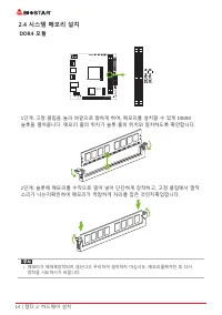
14 | 챕터 2: 하드웨어 설치 2�4 시스템 메모리 설치 DDR4 모듈 1단계: 고정 클립을 눌러 바깥으로 향하게 하여, 메모리를 설치할 수 있게 DIMM 슬롯을 열어줍니다. 메모리 홈의 위치가 슬롯 홈의 위치와 일치하도록 확인합니다. 2단계: 슬롯에 메모리를 수직으로 밀어 넣어 단단하게 장착하고, 고정 클립에서 딸깍 소리가 나는지확인하여 메모리가 적합하게 자리를 잡은 것인지확입합니다. » 메모리가 제대로장착되지 않는다고 무리하게 설치하지 마십시오. 메모리를제거한 후 다시 장착을 시도하시기 바랍니다.
Page 109 - 메모리 용량; DIMM소켓 위치; 듀얼 채널 메모리 설치; 듀얼 채널 상태; • Radeon Vega 그래픽 프로세서가 탑재 된 AMD
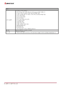
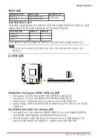
챕터 2: 하드웨어 설치 | 15 B550T-SILVER 메모리 용량 DIMM소켓 위치 DDR4 모듈 총 메모리 크기 DDR4_A 8GB/16GB/32GB 최대 64GB. DDR4_B 8GB/16GB/32GB 듀얼 채널 메모리 설치 듀얼 채널 기능을 활성화 하기 위해서는 다음의요구사항을 참조하시기 바랍니다: 동일 용량의 메모리 한 짝(2개를 아래의표와 같이 설치하여 주십시오. 듀얼 채널 상태 DDR4_A DDR4_B 비활성화 O X 비활성화 X O 가능 O O (O는 메모리가 설치된 상태를, X는 메모리가 설치되지 않은 상태를 의미...
Page 110 - 확장 카드 설치; 다음의 단계에 따라 확장 카드를 장착할 수 있습니다 :
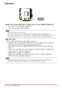
16 | 챕터 2: 하드웨어 설치 WIFI6: M�2 (E Key) 슬롯 (M�2 (E Key) Wi-Fi 카드는 제공되지 않습니다) • M.2 소켓 2230 타입 모듈을 지원합니다.• Wi-Fi 및 Bluetooth 모듈 지원합니다. » CPU에 따라 다른 속도가 있습니다. » PCIe 4.0은 AMD ® Ryzen™ 3 세대 Matisse 및 4 세대 Vermeer CPU로 제한됩니다. » M.2 (M Key) 소켓 (M2_PCIEG4_64G_SATA) : 대역폭은 CPU에 따라 다릅니다. PCI-E 4.0 x4 (64Gb/s)...
Page 113 - 이 커넥터들은 SATA 케이블을 통해 SATA 하드 디스크 드라이브에 연결됩니다.
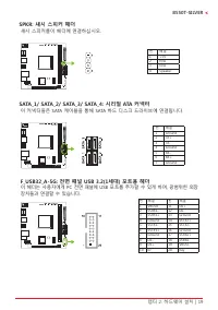
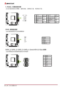
챕터 2: 하드웨어 설치 | 19 B550T-SILVER SPKR: 섀시 스피커 헤더 섀시 스피커를이 헤더에 연결하십시오. 핀 배열 1 +5V 2 N/A 3 N/A 4 Speaker SATA_1/ SATA_2/ SATA_3/ SATA_4: 시리얼 ATA 커넥터 이 커넥터들은 SATA 케이블을 통해 SATA 하드 디스크 드라이브에 연결됩니다. 핀 배열 1 Ground 2 TX+ 3 TX- 4 Ground 5 RX- 6 RX+ 7 Ground F_USB32_A-5G: 전면 패널 USB 3�2(1세대) 포트용 헤더 이 헤더는 사용자에게 ...
Page 116 - Debug LED: 디버그 LED 표시등; 이 LED는 마더 보드의 상태를 나타냅니다.
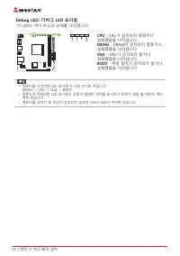
22 | 챕터 2: 하드웨어 설치 Debug LED: 디버그 LED 표시등 이 LED는 마더 보드의 상태를 나타냅니다. CPU - CPU가 감지되지 않았거나 실패했음을 나타냅니다. DRAM - DRAM이 감지되지 않았거나 실패했음을 나타냅니다. VGA - GPU가 감지되지 않거나 실패했음을 나타냅니다. BOOT - 부팅 장치가 감지되지 않거나 실패했음을 나타냅니다. » 컴퓨터를 시작하면 LED 표시등이 다음 순서로 켜집니다. DRAM → CPU → VGA → BOOT » 컴퓨터가 준비되면 LED 표시등이 오류가 발생한 위치를 표시하...
Page 117 - �1 UEFI 바이오스 설정; • 바이오스 설정 프로그램은 컴퓨터의 바이오스 설정을 보거나 변경할 때 사용됩니다.
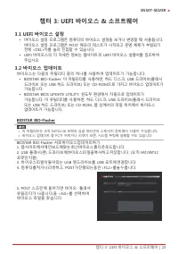
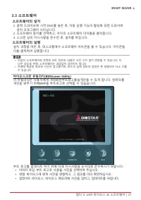
챕터 3: UEFI 바이오스 & 소프트웨어 | 23 B550T-SILVER 챕터 3: UEFI 바이오스 & 소프트웨어 3�1 UEFI 바이오스 설정 • 바이오스 설정 프로그램은 컴퓨터의 바이오스 설정을 보거나 변경할 때 사용됩니다. 바이오스 설정 프로그램은 POST 메모리 테스트가 시작되고 운영 체제가 부팅되기 전에 <DEL>키를 눌러 진입할 수 있습니다. • UEFI 바이오스의 더 자세한 정보는 웹사이트의 UEFI 바이오스 설명서를 참조하여 주십시오. 3�2 바이오스 업데이트 바이오스는 다음의 유틸리티 중...
Page 120 - 바이오스의 백업
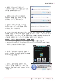
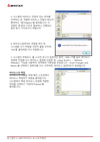
26 | 챕터 3: UEFI 바이오스 & 소프트웨어 5. 시스템의 바이오스 파일이 있는 위치를 선택하신 후, 적합한 바이오스 파일이 맞는지 확인하고 “열기(Open)”를 클릭합니다. 이 과정은 몇 분의 시간이 필요하니, 진행되는 동안 잠시 기다리시기 바랍니다. 6. 바이오스업데이트 과정을 마친 후, 시스템을 다시 부팅할 것인지 물을 것이며, “OK”를 클릭하면 다시 부팅합니다. 7. 시스템이 부팅되고, 풀 스크린 로고가 등장하는 동안, <DEL>키를 눌러 바이오스 설정에 진입합니다. 바이오스 설정에 진입한 후, &...
Page 121 - 소프트웨어의 설치; 광학 드라이브에 시작 DVD를 넣은 후, 자동 실행 기능이 활성화 되면 드라이버; 소프트웨어의 실행; 부트 로고를 업데이트 하기 위해 아래 지시사항을 순서대로 준수하시기 바랍니다 :
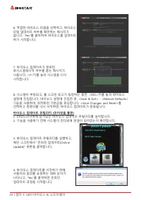
챕터 3: UEFI 바이오스 & 소프트웨어 | 27 B550T-SILVER 3�3 소프트웨어 소프트웨어의 설치 1. 광학 드라이브에 시작 DVD를 넣은 후, 자동 실행 기능이 활성화 되면 드라이버 설치 프로그램이 나타납니다. 2. 소프트웨어 설치를 선택하고, 각각의 소프트웨어 타이틀을 클릭합니다.3. 스크린 상의 지시사항을 준수한 후, 설치를 마칩니다. 소프트웨어의 실행 설치 과정을 마친 후, 데스크톱에서 소프트웨어 아이콘을 볼 수 있습니다. 아이콘을 더블-클릭하여 실행합니다. » 다음의 소프트웨어와 관련된 모든 정보와 내용...
Page 122 - 시스템 정보; 이 시스템 정보 탭은 시스템의 기본적인 정보와 사양을 제공합니다.
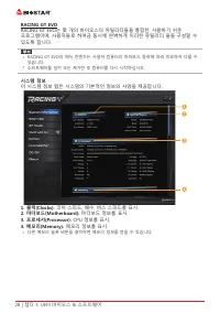
28 | 챕터 3: UEFI 바이오스 & 소프트웨어 RACING GT EVO RACING GT EVO는 몇 개의 바이오스타 유틸리티들을 통합한, 사용하기 쉬운 프로그램이며, 사용자들로 하여금 동시에 완벽하게 이러한 유틸리티 들을 구성할 수 있도록 합니다. » RACING GT EVO의 메뉴 컨텐츠는 사용자 컴퓨터의 마더보드 종류에 따라 미묘하게 다를 수 있습니다. » 소프트웨어를 설치 또는 제거한 후 컴퓨터를 다시 시작하십시오. 시스템 정보 이 시스템 정보 탭은 시스템의 기본적인 정보와 사양을 제공합니다. 1� 클럭(Cloc...
Page 125 - RAZER앱을 연결해메인보드RGB 색상 동기화; LED 유형 프로젝트 설정을 동기화 할 수 있습니다.
챕터 3: UEFI 바이오스 & 소프트웨어 | 31 B550T-SILVER 비비드 LED DJ(Vivid LED DJ) 선명한 LED DJ는 RGB LED 장치 인 ARMOR GEAR의 색 구성표를 조정할 수 있습니다. 1� LED컴맨더: LED 모델선택. • Default: 모든설정값을기본값으로복구. (파란불) • RAZER: RAZER앱을 연결해메인보드RGB 색상 동기화 » RAZER 모드를사용할경우 RACING GT EVO소프트웨어를끄면 LED 조명이기본상태로돌아갑니다. » RAZER 모드는 RAZER 소프트웨어와의연결...
Page 127 - 버튼을 클릭하여 CPU와; 변경했던 한 가지 항목의 수치를 기본값으로 복구.
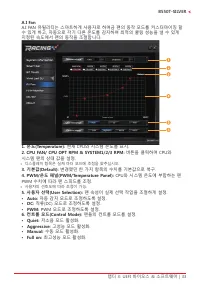
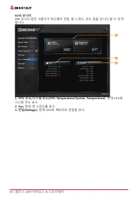
챕터 3: UEFI 바이오스 & 소프트웨어 | 33 B550T-SILVER A�I Fan A.I FAN 유틸리티는 스마트하게 사용자로 하여금 팬의 동작 모드를 커스터마이징 할 수 있게 하고, 자동으로 각기 다른 온도를 감지하여 최적의 쿨링 성능을 낼 수 있게 지정된 속도에서 팬의 동작을 조절합니다. 1� 온도(Temperature): 현재 CPU와 시스템 온도를 표시. 2� CPU FAN/ CPU OPT RPM & SYSTEM1/2/3 RPM: 버튼을 클릭하여 CPU와 시스템 팬의 상태 값을 설정. » 디스플레이 항목...
Page 128 - 현재 CPU와
34 | 챕터 3: UEFI 바이오스 & 소프트웨어 H/W 모니터 HW 모니터 탭은 사용자가 하드웨어 전압, 팬 스피드, 온도 등을 모니터 할 수 있게 합니다. 1� CPU 온도/시스템 온도(CPU Temperature/System Temperature): 현재 CPU와 시스템 온도 표시. 2� Fan: 현재 팬 스피드를 표시. 3� 전압(Voltage): 현재 CPU와 메모리의 전압을 표시.
Page 129 - 추후 사용을 위해 프로파일 수치를 저장.
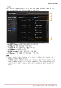
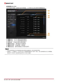
챕터 3: UEFI 바이오스 & 소프트웨어 | 35 B550T-SILVER OC/OV OC/OV 탭은 오버클럭킹(OC)/전압(OV) 설정 프로파일을 저장하고 로딩할 수 있게 하여, 시스템 클럭과 전압 설정을 변경할 수 있게 합니다. 1� 오버클럭킹(OC): 오버클럭킹 프로파일 수치를 조정. 2� 과전압(OV): 전압 프로파일 수치를 조정. 3� 기본값(Default): 변경사항을 기본값으로 복구. 4� 적용(Apply): 변경사항을 적용. 5� 불러오기(Load): 파일에서 프로파일 수치를 로딩. 6� 저장(Save): 추후...
Page 130 - About 메뉴는 버전 정보를 표시합니다.
36 | 챕터 3: UEFI 바이오스 & 소프트웨어 About About 메뉴는 버전 정보를 표시합니다.
Page 131 - 설정 가이드는 사용자의 마더보드와 운영 체제를 자동으로 감지합니다.; A� 드라이버 설치
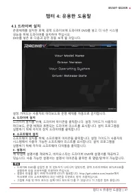
챕터 4: 유용한 도움말 | 37 B550T-SILVER 챕터 4: 유용한 도움말 4�1 드라이버 설치 운영체제를 설치한 후에, 광학 드라이브에 드라이버 DVD를 넣고 더 나은 시스템 성능을 위해 드라이버를 설치하여 주십시오.DVD를 넣은 후 다음과 같은 창을 보게 될 것입니다. 설정 가이드는 사용자의 마더보드와 운영 체제를 자동으로 감지합니다. A� 드라이버 설치 드라이버 설치를 위해, 드라이버 아이콘을 클릭합니다. 설정 가이드가 사용자의 마더보드, 운영 체제와 호환되는 드라이버 리스트를 표시합니다. 설치 프로그램을 실행하기 위해...
Page 132 - AMI 바이오스 비프 코드; 부트 블록 비프 코드; POST 바이오스 비프 코드; 비프음 횟수; �3 AMI 바이오스 포스트 코드; 코드 설명
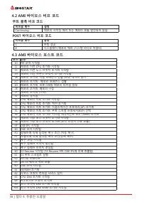
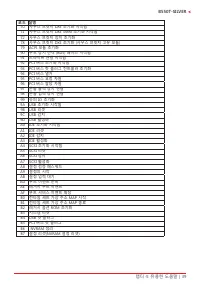
38 | 챕터 4: 유용한 도움말 4�2 AMI 바이오스 비프 코드 부트 블록 비프 코드 비프음 횟수 설명 Continuing 메모리 사이징 에러 또는 메모리 모듈 발견되지 않음 POST 바이오스 비프 코드 비프음 횟수 설명 1 부팅 성공 8 디스플레이 메모리 에러 (시스템 비디오 어댑터) 4�3 AMI 바이오스 포스트 코드 코드 설명 10 PEI 코어 시작됨11 메모리 이전 CPU 초기화 시작됨15 메모리 이전 노스 브릿지 초기화 시작됨19 메모리 이전 사우스 브릿지 초기화 시작됨2B 메모리 초기화. 직렬 프레즌스 검출 (SPD)...
Page 134 - 전원 케이블이 제대로 연결되어 있는지
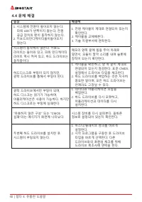
40 | 챕터 4: 유용한 도움말 4�4 문제 해결 증상 해결책 1. 시스템에 전원이 들어오지 않는다. 파워 LED가 반짝이지 않는다; 전원 공급 장치의 팬이 동작하지 않는다. 2. 키보드의인디케이터불이들어오지 않는다. 1. 전원 케이블이 제대로 연결되어 있는지 확인한다. 2. 케이블을 교체해본다.3. 기술 지원부서에 연락한다. 시스템이 동작하지 않는다. 키보드 라이트는 들어와 있고, 파워 인디케이터 라이트 역시 켜져 있고, 하드 드라이브는 동작중이다. 메모리 양쪽 끝에 힘을 주어 아래로 밀면서, 모듈이 딸깍 소리를 내며 슬롯에 장...
Page 135 - CPU의 과열
챕터 4: 유용한 도움말 | 41 B550T-SILVER CPU의 과열 시스템에 전원을 인가하고 수 초 후에 저절로 시스템이 꺼진다면 그것은 CPU 보호 기능이 활성화된 것을 의미합니다. CPU가 과열되면, 마더보드는 CPU의 손상을 방지하기 위해 자동으로 전원을 차단하며, 시스템은 다시 전원이 들어오지 않을 수 있습니다. 이런 경우에, 더블 체크가 필요합니다:1. CPU 쿨러 표면이 CPU 표면 위에 평평하게 자리잡고 있는지 살펴봅니다.2. CPU 팬이 정상적으로 도는지 체크합니다.3. CPU 팬 스피드가 CPU 동작 속도와 적합...
Page 136 - RAID 기능; RAID 정의; 오차를 요구하지 않는 환경을 위해 의도된 기술입니다.; 특징과 장점; 컨트롤러가 정상적인 다른 드라이브로 전환합니다.
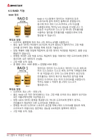
42 | 챕터 4: 유용한 도움말 4�5 RAID 기능 RAID 정의 RAID 0 시스템에서 데이터는 어레이의 모든 드라이브에 걸쳐 씌여진 블록으로 분할됩니다. 동시에 여러 개의 디스크(적어도 2개 이상)를 사용함으로써, 뛰어난 I/O 성능을 선사합니다. 이 성능은 이상적으로 디스크 당 하나의 컨트롤러를 사용하는 멀티플 컨트롤러를 사용함으로써 더욱 향상될 수 있습니다. 특징과 장점 • 드라이브: 플랫폼에 따라 최소 2개, 최대 6-8개를 사용합니다.• 용도: 높은 데이터 처리량이 요구되며, 비교적 중요도가 떨어지거나 고장 허용 오차...
Page 137 - • 문제점: 데이터 중복을 위해 RAID 레벨 1과 같이 두 배의 가용 디스크 공간이
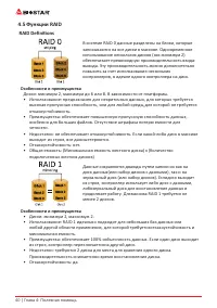
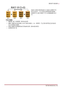
챕터 4: 유용한 도움말 | 43 B550T-SILVER RAID 10은 RAID 0과 RAID 1의 장점(과 단점)을 하나의 시스템에 조합해 놓은 것이며 데이터 전송 스피드를 가속하기 위해 각 디스크 세트에 걸쳐 스트라이핑을 사용하는 동안 세컨더리 디스크 세트(디스크 3번과 4번)의 모든 데이터를 미러링함으로써 안전함을 제공합니다. 특징과 장점 • 드라이브: 플랫폼에 따라 최소 4개, 최대 6개 또는 8개.• 장점: 고장 허용 오차와 성능에 모두 최적화되어 있으며, 자동 중복을 허용합니다. 어레이에 있는 기타 RAID 레벨을 함께...
Page 138 - 이 페이지는 의도적으로 비워 둔 것입니다
Page 139 - 防靜電操作規則
FCC條款 本裝置經測試,證實依據FCC規範第15篇規定,符合Class B數位裝置的限制。這些限制意 旨在提供合理的保護以防範有害的干擾。本設備會產生、使用並發出無線射頻能量,如未 依指示進行安裝與使用,可能會對無線電通訊造成有害的干擾。然而,無法保證在任一特 定安裝情況下不會產生任何干擾。如果本設備確實對無線電或電視收訊造成有害的干擾 (可 透過開啟和關閉設備電源的方式確定),則我們鼓勵使用者嘗試下列其中一項或多項方式來 改善干擾情況: • 重新調整接收天線的方向或位置。 • 增加設備與接收器之間的間隔距離。 • 將設備連接至與接收器所接電路不同的電源插座。 • 諮詢經銷商或有經驗的無線電...
Page 140 - 目錄; 第一章: 主板介绍 �������������������������������������������������������������������������������������������������������
2 | 目錄 目錄 第一章: 主板介绍 ������������������������������������������������������������������������������������������������������� 3 1.1 前言 ............................................................................................................................................... 3 1.2 包裝配件 ...............
Page 142 - 主板特性
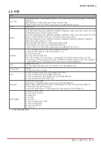
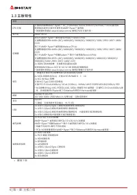
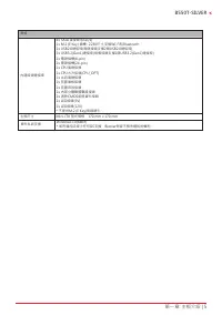
4 | 第一章: 主板介绍 1�3 主板特性 規格 CPU支援 支援AM4插槽AMD ® Ryzen™ 第三代(Matisse/ Renoir)和第四代(Vermeer/ Future)處理器 透過BIOS更新支援未來更新的AMD ® Ryzen™處理器 * 請瀏覽映泰網站 www.biostar.com.tw 獲得CPU的支援列表。 晶片組 AMD ® B550 記憶體 第四代AMD ® Ryzen™處理器(Vermeer/ Future CPUs): 支援雙通道DDR4 4400+(OC)/ 4000(OC)/ 3800(OC)/ 3600(OC)/ 3200/ 2933/ 2667/ 2...
Page 145 - 正面
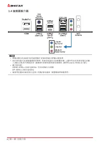
Page 146 - 背面
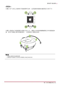
Page 148 - 步驟1: 將散熱片和風扇零件放置在支架上。散熱片夾對準插座並固定凸耳,再將彈簧夾
10 | 第二章: 硬體安裝 步驟4: 固定CPU,將拉桿閉合。 » 請於拔除CPU插槽之前,關閉電源。 2�2 散热片<類型A> 步驟1: 將散熱片和風扇零件放置在支架上。散熱片夾對準插座並固定凸耳,再將彈簧夾 扣到固定凸耳上。 步驟2: 將另一邊的固定夾向下壓,扣住支架上的塑膠凸耳。然後固定,使風扇和散熱片 扣住支架底座。
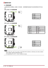
Page 150 - 此風扇接頭支援電腦上設置的冷卻風扇,風扇電纜和連接器可能因風扇製造商而有差
12 | 第二章: 硬體安裝 2�3 風扇接頭 此風扇接頭支援電腦上設置的冷卻風扇,風扇電纜和連接器可能因風扇製造商而有差 異。 CPU_FAN: CPU風扇接頭 針 定義1 接地 2 +12V 3 Sense 4 AI Fan Control CPU_OPT: CPU風扇接頭 PWM模式 DC模式 針 定義 針 定義 1 接地 1 接地 2 +12V 2 Voltage Control 3 Sense 3 Sense 4 Speed Control Signal 4 NC SYS_FAN1: 系統風扇接頭 針 定義1 接地 2 +12V 3 Sense 4 AI Fan Control » ...
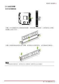
Page 151 - DDR4記憶體模組; 步驟1: 向外按壓固定夾以解鎖DIMM插槽。 對準插槽上的DIMM,以使DIMM上的槽口
第二章: 硬體安裝 | 13 B550T-SILVER 2�4 系統記憶體 DDR4記憶體模組 步驟1: 向外按壓固定夾以解鎖DIMM插槽。 對準插槽上的DIMM,以使DIMM上的槽口 與插槽上的缺口符合。 步驟2: 垂直將DIMM牢固地插入插槽,直到固定夾扣跳回原位,並且DIMM正確就位。 » 如果DIMM未順利插入,請勿強行插入按壓安裝。請將其完全拉出後重試。
Page 152 - 記憶體容量; DIMM插槽位置; 雙通道記憶安裝; 為啓動主板雙通道功能,使用記憶體模組必須符合以下要求: 成對安裝相同密度的記憶; 雙通道狀態; • AMD
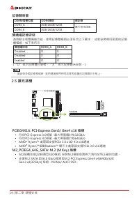
14 | 第二章: 硬體安裝 記憶體容量 DIMM插槽位置 DDR4模组 總記憶 DDR4_A 8GB/16GB/32GB 最大為 64GB. DDR4_B 8GB/16GB/32GB 雙通道記憶安裝 為啓動主板雙通道功能,使用記憶體模組必須符合以下要求: 成對安裝相同密度的記憶 體模組。如下表所示 雙通道狀態 DDR4_A DDR4_B Disabled O X Disabled X O Enabled O O (“O”表示記憶體已安裝,“X ”表示記憶體未安裝。) » 當安裝多個記憶模組時,我們建議使用相同品牌和容量的記憶體於主板上。 2�5 擴充插槽 PCIEG4X16: PCI-Exp...
Page 153 - 安裝擴充卡
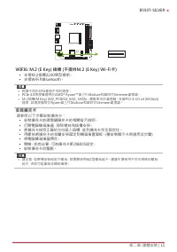
第二章: 硬體安裝 | 15 B550T-SILVER WIFI6: M�2 (E Key) 插槽 (不提供M�2 (E Key) Wi-Fi卡) • 支援M.2插槽2230類型模組。 • 支援WiFi和Bluetooth。 » 根據不同的CPU會有不同的速度。 » PCIe 4.0速度僅適用於AMD ® Ryzen™第三代Matisse和第四代Vermeer處理器。 » M.2插槽(M Key) (M2_PCIEG4_64G_SATA) : 頻寬取決於處理器。支援PCI-E 4.0 x4 (64Gb/s) 速度,該速度僅限於Ryzen第三代Matisse和第四代Vermeer處理器。 安裝擴...
Page 155 - 為了更好的相容性,我們建議使用標準的ATX24-pin電源供應此插槽的電源。
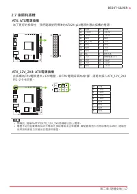
第二章: 硬體安裝 | 17 B550T-SILVER 2�7 接頭和插槽 ATX: ATX電源插槽 為了更好的相容性,我們建議使用標準的ATX24-pin電源供應此插槽的電源。 針 定義 針 定義 13 +3.3V 1 +3.3V 14 -12V 2 +3.3V 15 接地 3 接地 16 PS_ON 4 +5V 17 接地 5 接地 18 接地 6 +5V 19 接地 7 接地 20 NC 8 PW_OK 21 +5V 9 喚醒電壓+5V 22 +5V 10 +12V 23 +5V 11 +12V 24 接地 12 +3.3V ATX_12V_2X4: ATX電源插槽 此插槽為CPU電路提...
Page 158 - 此接頭提供12V電源與RGB控制訊號,可連接RGB LED裝置(5050 SMD)。; 此接頭提供5V電源與數據控制訊號,可連接ARGB LED裝置 (WS2818B)。; LED燈; 下面的LED燈由RACING GT EVO軟體控制。請參閱3.3章節的軟體設定。
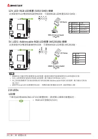
20 | 第二章: 硬體安裝 12V_LED: RGB LED裝置 (5050 SMD) 接頭 此接頭提供12V電源與RGB控制訊號,可連接RGB LED裝置(5050 SMD)。 針 電纜顏色 定義 1 12V (黑色) VCC12 2 G (綠色) LED_GREEN 3 R (紅色) LED_RED 4 B (藍色) LED_BLUE 5V_LED1: Addressable RGB LED裝置 (WS2818B) 接頭 此接頭提供5V電源與數據控制訊號,可連接ARGB LED裝置 (WS2818B)。 針 定義1 VCC5 2 數據 3 N/A 4 接地 » 請確保並正確的將針腳連接至...
Page 159 - LED指示燈顯示主板的檢測狀態。
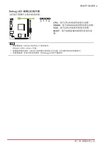
第二章: 硬體安裝 | 21 B550T-SILVER Debug LED: 檢測LED指示燈 LED指示燈顯示主板的檢測狀態。 CPU - 表示CPU未檢測到或發生故障。 DRAM - 表示DRAM未檢測到或發生故障。 VGA - 表示GPU未檢測到或發生故障。 BOOT - 表示啟動設備未檢測到或發生故 障。 » 啟動電腦後,LED指示燈將按以下順序點亮: DRAM→CPU→VGA→引導。 » 當電腦準備就緒時,LED指示燈將顯示錯誤發生的位置,並持續亮著直到問題解決。 » 啟動電腦後,如果未檢測到異常,則Debug LED將不會點亮。
Page 160 - �1 UEFI BIOS設定
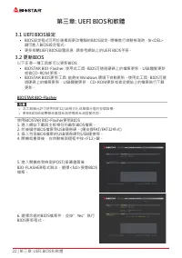
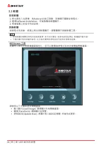
22 | 第三章: UEFI BIOS和軟體 第三章: UEFI BIOS和軟體 3�1 UEFI BIOS設定 • BIOS設定程式可用於查看與更改電腦的BIOS設定。開機進行自動檢測時,按<DEL> 鍵可進入BIOS設定程式。 • 更多相關UEFI BIOS設置訊息,請參考網站上的UEFI BIOS手册。 3�2 更新BIOS 以下任意一種工具都可以更新BIOS: • BIOSTAR BIO-Flasher: 使用此工具,BIOS可透過硬碟上的檔案更新、USB驅動更新 或者CD-ROM 更新。 • BIOSTAR BIOS更新工具: 能夠在Windows 環境下自動更新。使用此...
Page 161 - BIOS更新工具(通過網路)
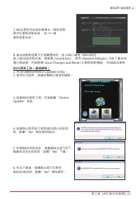
第三章: UEFI BIOS和軟體 | 23 B550T-SILVER 7. BIOS更新完成後則會彈出一個對話框, 要求您重新啟動系統。 按<Y>鍵 重新啟動系統。 8. 當系統啟動並顯示全螢幕標誌時,按<DEL>鍵進入BIOS設定。 進入BIOS設定程式後,請選擇<Save&Exit>,使用<Restore Defaults>功能下載系統 優化預設值,然後選擇<Save Changes and Reset>以重新啟動電腦。 完成BIOS更新。 BIOS更新工具(通過網路) 1. 用DVD驅動安裝BIOS Update Utilit...
Page 162 - BIOS更新工具(通過BIOS文件)
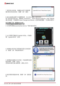
24 | 第三章: UEFI BIOS和軟體 7. 更新程式结束後,螢幕跳出提示您重新開 機引導系统的對話框。點擊”OK”重啟。 8. 當系統啟動並顯示全螢幕標誌時,按<DEL>鍵進入BIOS設定。 進入BIOS設定程式後,請選擇<Save&Exit>,使用<Restore Defaults>功能下載系統 優化預設值,然後選擇<Save Changes and Reset>以重新啟動電腦。 完成BIOS更新。 BIOS更新工具(通過BIOS文件) 1. 用DVD驅動安裝BIOS更新工具。 2. 從我們的網站www.biostar.com.tw 下...
Page 163 - 優化預設值,然後選擇以重新啟動電腦。 完成BIOS更新。; BIOS備份; 點擊BIOS備份按鈕,選擇備份檔案內的合適目
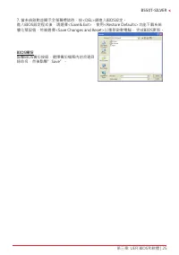
第三章: UEFI BIOS和軟體 | 25 B550T-SILVER 7. 當系統啟動並顯示全螢幕標誌時,按<DEL>鍵進入BIOS設定。 進入BIOS設定程式後,請選擇<Save&Exit>,使用<Restore Defaults>功能下載系統 優化預設值,然後選擇<Save Changes and Reset>以重新啟動電腦。 完成BIOS更新。 BIOS備份 點擊BIOS備份按鈕,選擇備份檔案內的合適目 錄命名,然後點擊”Save”。
Page 164 - BIOScreen 工具
26 | 第三章: UEFI BIOS和軟體 3�3 軟體 安裝軟體 1. 將光碟放入光碟機,若Autorun功能已啓動,則會顯示驅動安裝程式。 2. 選擇Software Installation,然後點擊各軟體圖示。 3. 根據螢幕上的指令完成安裝。 啓動軟體 安裝程式完成後,桌面上將出現軟體圖示。請雙擊圖示啓動軟體工具。 » 所有軟體的相關訊息和内容若有變更,恕不另行通知。為使系統性能更佳,軟體會不斷升級。 » 下面的圖片和訊息僅供參考,此主板的實際訊息和設定可能與手册略有差異。 BIOScreen 工具 此實用工具可以將開機畫面個性化。您可以選擇BMP格式來自定義電腦開機畫面。 請參照...
Page 165 - RACING GT EVO Utility
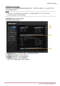
第三章: UEFI BIOS和軟體 | 27 B550T-SILVER RACING GT EVO Utility RACING GT EVO軟體配置數個映泰的實用程式,使用戶更方便操作,並允許用戶可依 序使用這些實用程式。 » RACING GT EVO軟體之選單内容將略有不同,具體項目配置取决於用户所使用的主板。 » 安裝或删除軟體後,請重新啓動電腦。 系統訊息(System information) 提供您基本系統訊息概述。 1� 時脈頻率(Clocks): 顯示核心頻率、倍頻和匯流排速度。 2� 主板(Motherboard): 顯示主板訊息。 3� 處理器(Processor): 顯...
Page 170 - � Default:; DC
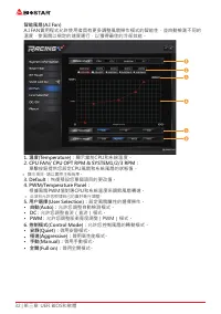
32 | 第三章: UEFI BIOS和軟體 智能風扇(A�I Fan) A.I FAN實用程式允許使用者具有更多調整風扇操作模式的智能性,並自動檢測不同的 溫度,使風扇以規定的速度運行,以獲得最佳的冷卻效能。 1� 溫度(Temperature): 顯示當前CPU和系統溫度。 2� CPU FAN/ CPU OPT RPM & SYSTEM1/2/3 RPM: 單擊按鈕提供您設定CPU風扇和系統風扇的狀態值。 » 顯示項目,請以實際主板為準。 3� Default: 恢復預設您單個項目的更改值。 4� PWM/Temperature Panel: 根據風扇PWM值對應CPU和系統溫度...
Page 171 - � 風扇轉速:; 顯示當前風扇速度。
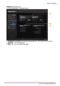
第三章: UEFI BIOS和軟體 | 33 B550T-SILVER 硬體監測(H/W Monitor) 允許您監控硬體電壓,風扇轉速和溫度。 1� 處理器溫度/系統溫度(CPU/System Temperature): 顯示當前CPU和系統溫度。 2� 風扇轉速: 顯示當前風扇速度。 3� 電壓: 顯示CPU和記憶體的當前電壓。
Page 173 - 此選單顯示Racing GT EVO Utility版本訊息。
第三章: UEFI BIOS和軟體 | 35 B550T-SILVER 關於(About) 此選單顯示Racing GT EVO Utility版本訊息。
Page 174 - 驅動程式安裝注意事項; A� 驅動程式安裝
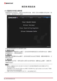
36 | 第四章:幫助訊息 第四章:幫助訊息 4�1 驅動程式安裝注意事項 為獲得更好的系統性能,在操作系統安裝完成後,請插入您的系統驅動光碟並安裝。插 入DVD後,將出現如下所示畫面。 此設定將自動檢測您的主板和操作系統。 A� 驅動程式安裝 安裝驅動程式,請點擊Driver圖示。設定指南將自動檢測您的主板和操作系統。點擊各 設備驅動程式,以開始安裝程序。 B� 軟體安裝 安裝軟體,請點擊Software圖示。設定指南將列出系統可用軟體,點擊各軟體名稱,以 開始安裝程序。 C� 使用手册 除了書本形式的手册,我們也提供光碟形式的使用指南。點擊Manual圖示,瀏覽可用 相關使用指南。 » 若...
Page 175 - AMI BIOS 提示音代碼; 啓動區塊模組提示音代碼; BIOS 開機自檢提示音代碼; 提示音次數; AMI BIOS 開機自檢代碼; 代碼 含義
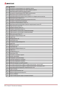
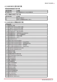
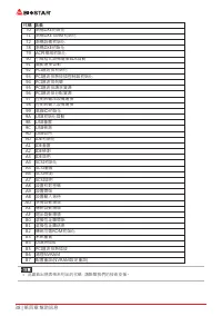
第四章:幫助訊息 | 37 B550T-SILVER 4�2 AMI BIOS 提示音代碼 啓動區塊模組提示音代碼 提示音次數 含義 持續提示音 記憶體錯誤或未找到記憶體模塊 BIOS 開機自檢提示音代碼 提示音次數 含義 1 系統引導成功 8 顯示記憶體錯誤(視訊介面卡) 4�3 AMI BIOS 開機自檢代碼 代碼 含義 10 PEI核心啓動11 CPU Pre-memory初始化啓動15 北橋Pre-memory初始化啓動19 南橋Pre-memory初始化啓動2B 記憶體初始化,讀取SPD數據 2C 記憶體初始化,檢測Memory presence 2D 記憶體初始化,程式化記憶體資訊...
Page 177 - 問題解答; 問題
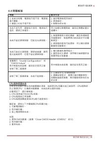
第四章:幫助訊息 | 39 B550T-SILVER 4�4 問題解答 問題 解决方法 1. 系統沒有電,電源指示燈不亮,電源風 扇不轉動。 2. 鍵盤上的指示燈不亮。 1. 確定電源線是否接好。 2. 更換線材。 3. 聯繫技術支援。 系統不起作用。鍵盤指示燈亮,電源指示 燈亮,硬碟正常運作。 用力按壓記憶體兩端,確保記憶體安置於 插槽中。 系統不能從硬碟啓動,但能從光碟啓動。 1. 檢查硬碟與主板的連線,確定各連線是 否確實接好,檢查標準CMOS設定中的驅 動類型。 2. 硬碟隨時都有可能壞掉,所以備份硬碟 數據是很重要的。 系統只能從光碟啓動。硬碟能被讀,應用 程式能被使用,但是不能從硬...
Page 178 - RAID 功能; RAID 定義; 性能及優點
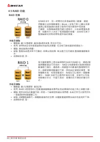
40 | 第四章:幫助訊息 4�5 RAID 功能 RAID 定義 在RAID 0中,同一時間內向多塊磁碟寫入數據,通過 把數據分成多個數據塊(Block)並執行寫入/讀出多個 磁碟以提高磁碟的速度分散到所有的硬碟中同時進 行讀寫,在整個磁碟陣列建立過程中,以系統環境為基 礎,指數的大小決定了每塊磁盤的容量。此技術可減少 整個磁碟的存取時間和提供高的頻寬。 性能及優點 • 驅動器: 最少2塊硬碟,最多達6塊或8塊,取決於平台。 • 使用: 使用RAID 0來提高磁碟的性能和流通量,但没有冗餘或錯誤修復能力。 • 優點: 增加磁碟的容量。 • 缺點: 整個系統是非常不可靠的,如果出現故障,無法進...
Page 180 - 2 | 附录:产品中有毒有害物质或元素的名称及含量; 附录:产品中有毒有害物质或元素的名称及含量
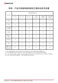
42 | 附录:产品中有毒有害物质或元素的名称及含量 附录:产品中有毒有害物质或元素的名称及含量 部件名称 有毒有害物质或元素 铅 (Pb) 汞 (Hg) 镉 (Cd) 六价铬 (Cr(VI)) 多溴联苯 (PBB) 多溴二苯醚 (PBDE) PCB板 O O O O O O 结构件 O O O O O O 芯片及其它 主动零件 X O O O O O 连接器 X O O O O O 被动电子元 器件 X O O O O O 焊接金属 O O O O O O 线材 O O O O O O 助焊剂,散 热 膏,标签 及其它耗材 O O O O O O O:表示该有毒有害物质在该部件所有均质材料中...