APC 750 - Manuals
APC 750 Uninterruptable Power Supply – Manual in PDF format online.
Manuals:
Manual APC 750


Summary
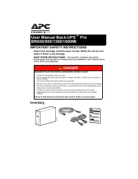
1 Introduction The APC Uninterruptible Power Supply (UPS) is designed to prevent blackouts, brownouts, sags, and surges from reaching your computer and other valuable electronic equipment. The UPS filters small utility line fluctuations and isolates your equipment from large disturbances by internal...
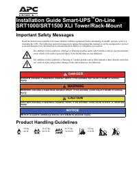
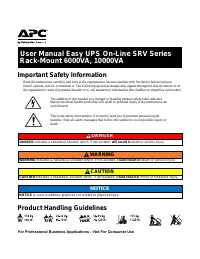
2 Positioning the UPS Place the UPS where it will be used. The UPS is heavy. Select a location sturdy enough to handle the weight. Do not operate the UPS where there is excessive dust or the temperature and humidity are outside the specified limits. P LACEMENT Mounting the UPS in a Rack The UPS is h...
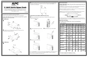
3 Installing and Connecting the Battery and Attaching the Front Bezel Step 1 Step 2 Step 3 Step 4 Connect battery plug to UPS. Tuck white battery cord into space above connector. Connecting Equipment and Power to the UPS S MART -UPS R EAR P ANEL 100/120V Models 120V Model Only: Site wiring fault ind...
APC Uninterruptable Power Supplies Manuals
-
 APC 650
User Manual
APC 650
User Manual
-
APC 650
Manual
-
 APC 1500
User Manual
APC 1500
User Manual
-
APC 1500
Manual
-
 APC 3000
User Manual
APC 3000
User Manual
-
APC 3000
Manual
-
 APC 10000
User Manual
APC 10000
User Manual
-
 APC Battery replacement kit RBC6
User Manual
APC Battery replacement kit RBC6
User Manual
-
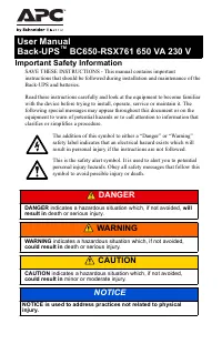 APC BC650
User Manual
APC BC650
User Manual
-
 APC BR500
User Manual
APC BR500
User Manual
-
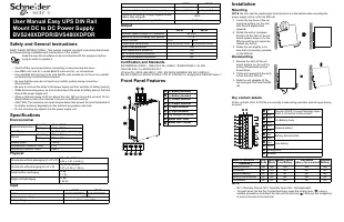 APC Easy
User Manual
APC Easy
User Manual
-
 APC Panel
User Manual
APC Panel
User Manual
-
 APC SMT3000
User Manual
APC SMT3000
User Manual
-
 APC SRT3000
User Manual
APC SRT3000
User Manual
-
APC SRT3000
Manual
-
 APC SY100
User Manual
APC SY100
User Manual
-
 APC UPS Smart-UPS 1000VA LCD 230V
User Manual
APC UPS Smart-UPS 1000VA LCD 230V
User Manual
-
 APC UPS Smart-UPS 1500VA LCD 230V
User Manual
APC UPS Smart-UPS 1500VA LCD 230V
User Manual
-
 APC UPS Smart-UPS 1500VA LCD RM 1U 230V
User Manual
APC UPS Smart-UPS 1500VA LCD RM 1U 230V
User Manual
-
 APC UPS Smart-UPS 2200VA LCD 230V
User Manual
APC UPS Smart-UPS 2200VA LCD 230V
User Manual