AEG HKB95540NB - User Manual

AEG HKB95540NB – User Manual, read for free online in PDF format. We hope this helps you resolve any issues you may have. If you have further questions, please contact us through the contact form.


Table of Contents:
- Page 2 – spend a few minutes reading to get the very best from it.; CUSTOMER CARE AND SERVICE; Always use original spare parts.; SAFETY INFORMATION; Before the installation and use of the appliance,
- Page 5 – SAFETY INSTRUCTIONS; Installation
- Page 7 – INSTALLATION; Before the installation
- Page 8 – Injectors replacement
- Page 9 – Electrical connection
- Page 10 – Replacement of the
- Page 12 – PRODUCT DESCRIPTION; Cooking surface layout
- Page 13 – Control panel layout; Control knob; Residual heat
- Page 14 – DAILY USE; Burner overview
- Page 16 – HINTS AND TIPS; Cookware; Hints and Tips for
- Page 17 – CARE AND CLEANING; General information
- Page 18 – Cleaning the spark plug
- Page 19 – TROUBLESHOOTING
- Page 20 – TECHNICAL DATA; Hob dimensions; Bypass diameters
- Page 21 – Other technical data; Gas burners for NATURAL GAS G20 20 mbar; SAUDI ARABIA - CUSTOMER SERVICE
- Page 22 – ENVIRONMENTAL CONCERNS
USER
MANUAL
EN
User Manual
Hob
HKB95540NB
"Loading the manual" means you need to wait until the file loads and becomes available for online reading. Some manuals are very large, and the time they take to appear depends on your internet speed.
Was this manual helpful?
About this manual
- Brand
- AEG
- Model
- HKB95540NB
- Document type
- User Manual
- Language(s)
- English
- Pages
- 24
- File size
- 683.9 KB
- Format
Summary
CONTENTS 1. SAFETY INFORMATION............................................................................................. 2 2. SAFETY INSTRUCTIONS.............................................................................................5 3. INSTALLATION.............................................
2. SAFETY INSTRUCTIONS This appliance is suitable for thefollowing markets: SA 2.1 Installation WARNING! Only a qualified person must install this appliance. WARNING! Risk of injury or damage to the appliance. • Remove all the packaging. • Do not install or use a damaged appliance. • Follow the inst...
• Prolonged intensive use of the appliance may call for additional ventilation, for example opening of a window, or more effective ventilation, for example increasing the level of mechanical ventilation where present. • This appliance is for cooking purposes only. It must not be used for other purpo...
Ask a question
Related manuals
Popular AEG Other
More AEG Other models
 AEG HK894400XG User Manual
 AEG HK953400FB User Manual
 AEG HK955070FB User Manual
 AEG HK956600FB User Manual
 AEG HKA6507RAD User Manual
 AEG HKB75NB540 User Manual
 AEG HL7275-M/GB User Manual
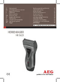 AEG HR 5625 User Manual
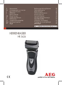 AEG HR 5626 User Manual
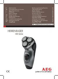 AEG HR 5654 User Manual
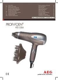 AEG HTD 5584 User Manual
 AEG HVB95450IB User Manual