Page 2 - INDICE; CONSIGLI E SUGGERIMENTI
2 IT INDICE Gentile Signora, Caro Signore, Se seguirà con cura le raccomandazionicontenute in questo Libretto Istruzioni,la sua Cappa si manterrà efficiente nel tempoe le consentirà di ottenere costantementele migliori prestazioni. CONSIGLI E SUGGERIMENTI 3 CARATTERISTICHE 4 INSTALLAZIONE 5 USO 7 MA...
Page 4 - CARATTERISTICHE; Ingombro; Componenti
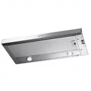
4 IT 1 12a 20 0 ÷ 152 280 L 260 150 ø CARATTERISTICHE Ingombro Tipo Cappa 60 90 L 598 898 Componenti Rif. Q.tà Componenti di Prodotto 1 1 Corpo Cappa completo di: Comandi, Luce,Gruppo Ventilatore, Filtri 20 1 Profilo chiusura Rif. Q.tà Componenti di Installazione 12a 4 Viti 4,2 x 44,4 Q.tà Documenta...
Page 5 - Foratura Piano di supporto e Montaggio Cappa
5 IT INSTALLAZIONE Foratura Piano di supporto e Montaggio Cappa MONTAGGIO CON VITI • Il Piano di supporto della Cappa deve essere rientrante di 220 mm dal Piano inferiore dei Pen-sili. • Forare ø 4,5 mm il supporto utilizzando la Dima di foratura in dotazione. • Praticare un foro ø 150 mm sul Piano ...
Page 6 - Connessioni
6 IT PROFILO DI CHIUSURA • Lo spazio tra il bordo della Cappa e la Parete di fondo può essere chiuso applicando il Profilo20 in dotazione con le Viti già predisposte aquesto scopo. Connessioni USCITA ARIA VERSIONE ASPIRANTE Per installazione in Versione Aspirante collegare la Cappa alla tubazione di...
Page 7 - USO; Quadro comandi
7 IT USO Quadro comandi L Luci Accende e spegne l’Impianto di Illuminazione. M Motore Accende e spegne il motore Aspirazione. V Velocità Determina le velocità di esercizio: 1. Velocità minima, adatta ad un ricambio d’aria continuo particolarmente si- lenzioso, in presenza di pochi vapori di cottura....
Page 8 - MANUTENZIONE; Filtri antigrasso; Sostituzione
8 IT A B MANUTENZIONE Filtri antigrasso PULIZIA FILTRI ANTIGRASSO METALLICI • Necessitano di essere lavati almeno ogni 2 mesi circa di utilizzo o più frequentemen-te, per un uso particolarmente intenso. • Togliere i Filtri uno alla volta, agendo sugli appositi agganci. • Lavare i Filtri evitando di ...
Page 9 - CONTENTS
9 GB RECOMMENDATIONS AND SUGGESTIONS 10 CHARACTERISTICS 11 INSTALLATION 12 USE 14 MAINTENANCE 15 CONTENTS Dear Customer, If you follow the recommendationscontained in this Instruction Manual,your appliance will give you constanthigh performance and will remainefficient for many years to come.
Page 10 - RECOMMENDATIONS AND SUGGESTIONS
10 GB RECOMMENDATIONS AND SUGGESTIONS INSTALLATION • The manufacturer will not be held liable for any damages resulting from incorrect or improper installation. • The minimum safety distance between the cooker top and the extractor hood is 650 mm. • Check that the mains voltage corresponds to that i...
Page 11 - CHARACTERISTICS; Dimensions
11 GB 0 ÷ 152 280 L 260 150 ø Hood Type 60 90 L 598 898 1 12a 20 CHARACTERISTICS Dimensions Components Ref. Q.ty Product Components 1 1 Hood Body, complete with: Controls, Light,Blower, Filters 20 1 Closing element Ref. Q.ty Installation Components 12a 4 Screws 4,2 x 44,4 Q.ty Documentation 1 Instru...
Page 12 - Drilling the Support surface and Fitting the Hood
12 GB 220 15 264 L1 Vf Hood Type 60 90 L 598 898 INSTALLATION Drilling the Support surface and Fitting the Hood SCREW FITTING • The hood support surface must be 220 mm above the bottom surface of the wall units. • Drill the support with a ø 4,5 mm drill bit, using the drilling template provided. • C...
Page 13 - Connections
13 GB CLOSING ELEMENT • The space between the edge of the hood and the rear wall can be closed by applying theelement 20 provided, using the screws suppliedfor this purpose. Connections DUCTED VERSION AIR EXHAUST SYSTEM When installing the ducted version, connect the hood to the chimney using either...
Page 14 - USE; Control panel
14 GB USE Control panel L Light Switches the lighting system on and off. M Motor Switches the extractor motor on and off. V Speed Sets the operating speed of the extractor: 1. Low speed, used for a continuous and silent air change in the presence of light cooking vapour. 2. Medium speed, suitable fo...
Page 15 - MAINTENANCE; Grease filters; Lighting
15 GB MAINTENANCE Grease filters CLEANING METAL GREASE FILTERS • The filters must be cleaned every 2 months o f o p e r a t i o n , o r m o r e f r e q u e n t l y f o rparticularly heavy usage. • Remove the filters, one at a time, after d i s c o n n e c t i n g t h e r e l a t i v e f a s t e n i ...
Page 16 - SOMMAIRE; CONSEILS ET SUGGESTIONS
16 FR SOMMAIRE Chère Madame, Cher Monsieur, Si vous suivez attentivement lesrecommandations contenues dans cemode d’emploi, votre hotte resteratoujours efficace, et fourniraconstamment les mêmes performances. CONSEILS ET SUGGESTIONS 17 CARACTERISTIQUES 18 INSTALLATION 19 UTILISATION 21 ENTRETIEN 22
Page 18 - CARACTERISTIQUES; Encombrement; Composants
18 FR 0 ÷ 152 280 L 260 150 ø 1 12a 20 CARACTERISTIQUES Encombrement Type de hotte 60 90 L 598 898 Composants Réf. Q.té Composants de Produit 1 1 Corps Hotte équipé de:Comandes,Lumière,Groupe Ventilateur,Filtres 20 1 Profil fermeture Réf. Q.té Composants pour l ’installation 12a 4 Vis 4,2 x 44,4 Q.t...
Page 19 - Perçage du Plan de support et Montage de la Hotte
19 FR INSTALLATION Perçage du Plan de support et Montage de la Hotte MONTAGE AU MOYEN DE VIS • Le Plan de support de la Hotte doit être monté plus en haut de 220 mm. par rapport au Planinférieur des Armoires murales. • Percer un trou de ø 4,5 mm. sur le support, en utilisant le Gabarit de perçage fo...
Page 20 - Branchements
20 FR 20 9 125 150 ø150 PROFIL DE FERMETURE • Il est possible de boucher l’espace entre le rebord de la Hotte et la Paroi du fond, enappliquant le Profil 20 fourni avec l’appareil, àl’aide des Vis déjà prévus à cet effet. Branchements SORTIE AIR VERSION ASPIRANTE En cas d’installation en version asp...
Page 21 - UTILISATION; Tableau de commande
21 FR UTILISATION Tableau de commande L Lumières Allume et éteint l’éclairage. M Moteur Allume et éteint le moteur aspiration V Vitesses Détermine les vitesses d’exploitation ainsi subdivisées:1. Vitesse minimale, pour un rechange d’air permanent particulièrementsilencieux en cas de faibles vapeurs ...
Page 22 - ENTRETIEN; Eclairage
22 FR A B ENTRETIEN Filtres anti-graisse NETTOYAGE FILTRES ANTI-GRAISSE METALLIQUES • Ils nécessitent d’être nettoyés environ tous les 2 mois d’emploi ou plus fréquemment en casd’emploi particulièrement intense. • R e t i r e r l e s f i l t r e s l ’ u n a p r è s l ’ a u t r e , e n intervenant su...
Page 23 - INHALTSVERZEICHNIS; EMPFEHLUNGEN UND HINWEISE
23 DE INHALTSVERZEICHNIS Sehr geehrte Damen und Herren, bitte lesen Sie die Bedienungsanleitungaufmerksam durch, damit Sie alleMöglichkeiten und Vorteile Ihrer neuenDunstabzugshaube voll nutzen könnenund über lange Zeit hin gute Leistungenerzielen. EMPFEHLUNGEN UND HINWEISE 24 CHARAKTERISTIKEN 25 MO...
Page 25 - CHARAKTERISTIKEN; Platzbedarf
25 DE 0 ÷ 152 280 L 260 150 ø 1 12a 20 Hauben-typ 60 90 L 598 898 CHARAKTERISTIKEN Platzbedarf Komponenten Pos. St. Produktkomponenten 1 1 Haubenkörper mit Schaltern,Beleuchtung,Gebläsegruppe,Filter 20 1 Abdeckprofil Pos. St. Montagekomponenten 12a 4 Schrauben 4,2 x 44,4 St. Dokumentation 1 Bedienun...
Page 26 - Bohren der Trägerplatte und Montage der Dunstabzugshaube
26 DE MONTAGE Bohren der Trägerplatte und Montage der Dunstabzugshaube MONTAGE MIT SCHRAUBEN • D i e H a u b e n - Tr ä g e r p l a t t e m u s s 2 2 0 m m o b e r h a l b d e r O b e r s c h r a n k - U n t e r f l ä c h epositioniert werden. • Mit Hilfe des beiliegenden Bohrplanes Löcher ø 4,5 mm ...
Page 27 - Anschlüsse
27 DE ABDECKPROFIL • D e r B e r e i c h z w i s c h e n H a u b e n k a n t e u n d Rückwand kann mit Hilfe des mitgeliefertenAbdeckprofils 20 und der für diesen Zweckvorgesehenen Schrauben geschlossen werden. 20 9 125 150 ø150 Anschlüsse ANSCHLUSS IN ABLUFTVERSION Bei Abluftbetrieb kann die Haube ...
Page 28 - BEDIENUNG; Bedienfeld
28 DE BEDIENUNG Bedienfeld L Beleucht Schaltet die Beleuchtung ein und aus. M Motor Schaltet den Gebläsemotor ein und aus. V Geschw. Steuert folgende Geschwindigkeitsstufen: 1. geringste Gebläsestufe, diese Stufe ist für einen ständigen und besondersleisen Luftaustausch bei geringer Kochdunstentwick...
Page 29 - Beleuchtung; WARTUNG; Fettfilter
29 DE A B Geruchsfilter (Umluftversion) AKTIVKOHLE-GERUCHSFILTER - FILTERAUSTAUSCH • Sie können weder gewaschen noch wiederver- w e n d e t w e r d e n u n d s i n d a l l e 4Betriebsmonatebzw. bei starkem Einsatz auchhäufiger auszutauschen. • Die Fettfilter entnehmen.• Die gesättigten Aktivkohle-Ge...
Page 30 - INHOUDSOPGAVE; ADVIEZEN EN SUGGESTIES
30 NL INHOUDSOPGAVE Geachte mevrouw, meneer, Als u de in deze Gebruiksaanwijzingbeschreven aanbevelingen zorgvuldigopvolgt, blijft uw kap steeds in goedestaat en zal hij altijd optimale prestatiesleveren. ADVIEZEN EN SUGGESTIES 31 EIGENSCHAPPEN 32 INSTALLATIE 33 GEBRUIK 35 ONDERHOUD 36
Page 32 - EIGENSCHAPPEN; Buitenafmetingen; Onderdelen
32 NL 0 ÷ 152 280 L 260 150 ø 0 ÷ 152 280 L 260 150 ø 1 12a 20 EIGENSCHAPPEN Buitenafmetingen Type Wasemkap 60 90 L 598 898 Onderdelen Ref. Productonderdelen 1 1 Wasemkap compleet met:Bedieningen,Licht, Ventilatorgroep, Filters 20 1 Sluitprofiel Ref. Installatieonderdelen 12a 4 Schroeven 4,2 x 44,4 ...
Page 33 - Boren van gaten in draagvlak en montage kap
33 NL INSTALLATIE Boren van gaten in draagvlak en montage kap MONTAGE MET SCHROEVEN • Het draagvlak van de kap moet 220 mm hoger zijn dan het ondervlak van de hangkastjes. • Boor een gat van ø 4,5 mm in de drager met behulp van de bijgeleverde boormal. • Boor een gat van ø 150 mm in het draagvlak me...
Page 34 - Aansluitingen
34 NL SLUITPROFIEL • De ruimte tussen de rand van de kap en de achterwand kan worden afgesloten met behulpvan het bijgeleverde profiel 20 met de voor ditdoel reeds aanwezige schroeven. Aansluitingen LUCHTUITLAAT AFZUIGVERSIE Bij installatie in afzuigversie, moet u de wasemkap met de uitlaatleiding v...
Page 35 - GEBRUIK; Bedieningspaneel
35 NL GEBRUIK Bedieningspaneel L Lichten Hiermee schakelt u de verlichting aan en uit M Motor Hiermee schakelt u de afzuigmotor aan en uit V Snelheid Instelling van de werkingssnelheid: 1. Minimumsnelheid, geschikt voor een continue en zeer stille luchtverversing, als er weinig kookdampen zijn. 2. G...
Page 36 - ONDERHOUD; Vetfilters; Verlichting
36 DE A B ONDERHOUD Vetfilters REINIGING VAN DE ZELFDRAGENDE METALEN VETFILTERS • De filters moeten eens in de 2 maanden of, bij bijzonder intensief gebruik, vaker gereinigdworden. • Verwijder de filters één voor één door de bevestigingen los te maken. • Was de filters en vermijd hierbij ze te buige...
Page 37 - ÍNDICE
37 ES CONSEJOS Y SUGERENCIAS 38 CARACTERÍSTICAS 39 INSTALACIÓN 40 USO 42 MANTENIMIENTO 43 Estimada señora, estimado señor, Si sigue con atención los consejos contenidos en estemanual de instrucciones, su campana funcionarásiempre de manera eficaz y podrá obtener siemprelas mejores prestaciones. ÍNDI...
Page 38 - CONSEJOS Y SUGERENCIAS; INSTALACIÓN
38 ES CONSEJOS Y SUGERENCIAS INSTALACIÓN • El fabricante declina cualquier responsabilidad debida a los daños provocados por una instalación incorrecta o no conforme con lasreglas. • La distancia mínima de seguridad entre la encimera y la campana debe ser de 650 mm. • Comprobar que la tensión de red...
Page 39 - CARACTERÍSTICAS; Dimensiones
39 ES 0 ÷ 152 280 L 260 150 ø 1 12a 20 Tipo Campana 60 90 L 598 898 CARACTERÍSTICAS Dimensiones Componentes Ref. Cant. Componentes del producto1 1 Cuerpo campana dotado con:mandos,luz,grupo de ventilación,filtros. 20 1 Perfil de cierre Ref. Cant. Componentes de instalación 12a 4 Tornillos 4,2 x 44,4...
Page 40 - Taladrado de la superficie de soporte y montaje de la campana
40 ES INSTALACIÓN Taladrado de la superficie de soporte y montaje de la campana MONTAJE CON TORNILLOS • La superficie de soporte de la campana debe encontrarse 220 mm por encima de la superfi-cie inferior del mueble colgante. • Taladrar ø 4,5 mm el soporte utilizando la p l a n t i l l a d e p e r f...
Page 41 - Conexiones
41 ES PERFIL DE CIERRE • El espacio entre el borde de la campana y la pared de fondo se puede cerrar aplicando elperfil 20 en dotación con los tornillos yapredispuestos para este objeto. Conexiones SALIDA DEL AIRE VERSIÓN FILTRANTE Para la instalación de la versión aspirante, conectar la campana al ...
Page 42 - Tablero de mandos
42 ES USO Tablero de mandos L Luces Enciende y apaga la instalación de iluminación. M Motor Enciende y apaga el motor de aspiración. V Velocidad Determina las velocidades de ejercicio. 1. Velocidad mínima, indicada para un recambio de aire continuo muy silencioso, en presencia de pocos vapores de co...
Page 43 - MANTENIMIENTO; Filtros antigrasa; Iluminación
43 ES MANTENIMIENTO Filtros antigrasa LIMPIEZA DE LOS FILTROS ANTIGRASA METÁLICOS Limpieza de los Filtros• R e q u i e r e n u n l a v a d o c a d a 2 m e s e s aproximadamente o más a menudo si su uso esmuy intenso. • Quitar los filtros uno por vez, operando en los enganches correspondientes. • Lav...