Page 3 - Save all warnings and instructions for future reference.; WORK AREA SAFETY; Keep work area clean and well lit.; ELECTRICAL SAFETY; Do not expose power tools to rain or wet conditions.; PERSONAL SAFETY; GENERAL SAFETY RULES; Dress properly. Do not wear loose clothing or; POWER TOOL USE AND CARE
3 − English WARNING: R e a d a l l s a f e t y w a r n i n g s , i n s t r u c t i o n s , illustrations and specifications provided with this power tool. Failure to follow all instructions listed below may result in electric shock, fire and/or serious injury. Save all warnings and instructions for ...
Page 4 - SERVICE
4 − English Keep cutting tools sharp and clean. Properly maintained cutting tools with sharp cutting edges are less likely to bind and are easier to control. Use the power tool, accessories and tool bits etc. in accordance with these instructions, taking into account the working conditions and t...
Page 5 - TABLE SAW SAFETY RULES; KICKBACK
5 − English TABLE SAW SAFETY RULES Provide auxiliary workpiece support to the rear and/or sides of the saw table for long and/or wide workpieces to keep them level. A long and/or wide workpiece has a tendency to pivot on the table’s edge, causing loss of control, saw blade binding and kickback. ...
Page 7 - SYMBOLS
7 − English SYMBOLS Some of the following symbols may be used on this tool. Please study them and learn their meaning. Proper interpretation of these symbols will allow you to operate the tool better and safer. SYMBOL NAME DESIGNATION/EXPLANATION Safety Alert Indicates a potential personal injury ha...
Page 8 - ELECTRICAL; DOUBLE INSULATION; ELECTRICAL CONNECTION; power supply that is 120 V, AC only (normal; POLARIZED PLUGS; Cord Length; POLARIZED
8 − English ELECTRICAL DOUBLE INSULATION Double insulation is a concept in safety in electric power tools, which eliminates the need for the usual three-wire grounded power cord. All exposed metal parts are isolated from the internal metal motor components with protecting insulation. Double insulate...
Page 9 - GLOSSARY OF TERMS
9 − English GLOSSARY OF TERMS Pilot Hole (drill presses and scroll saws) A small hole drilled in a workpiece that serves as a guide for drilling large holes accurately or for insertion of a scroll saw blade. Push Blocks (jointer planers) Device used to feed the workpiece over the jointer planer cutt...
Page 10 - FEATURES; PRODUCT SPECIFICATIONS
10 − English FEATURES PRODUCT SPECIFICATIONS Blade Arbor .............................................................. 5/8 in.Blade Diameter .......................................................... 10 in.Bevel Tilt .................................................................. 0˚ - 45˚ Rating...
Page 11 - KNOW YOUR TABLE SAW
11 − English FEATURES KNOW YOUR TABLE SAW See Figures 2 - 3. The safe use of this product requires an understanding of the information on the tool and in this operator’s manual as well as a knowledge of the project you are attempting. Before use of this product, familiarize yourself with all operati...
Page 12 - OPERATING COMPONENTS; SWITCH ASSEMBLY; SWITCH IN LOCKED POSITION
12 − English FEATURES MITER GAUGE - The miter gauge aligns the workpiece for a cross cut. The easy-to-read indicator shows the exact angle for a miter cut, with positive stops at 90° and 45°. MITER GAUGE GROOVES - The miter gauge rides in the grooves on the saw table. RIP FENCE - A sturdy metal fenc...
Page 13 - TOOLS NEEDED
13 − English TOOLS NEEDED The following tools (not included or drawn to scale) are needed for assembly and adjustment: Fig. 5 FRAMING SQUARE C-CLAMP PHILLIPS SCREWDRIVER COMBINATION SQUARE ADJUSTABLE WRENCHES
Page 14 - LOOSE PARTS
14 − English LOOSE PARTS Fig. 6 The following items are included with your table saw: A B C D A. Anti-Kickback Pawls .........................................................1B. Rip Fence ..........................................................................1C. Blade Guard .........................
Page 15 - ASSEMBLY; UNPACKING; MOUNTING HOLES
15 − English ASSEMBLY UNPACKING This product requires assembly. Carefully lift the saw from the carton and place it on a level work surface. WARNING: Do not use this product if any parts on the Loose Parts List are already assembled to your product when you unpack it. Parts on this list are not as...
Page 16 - ASSEMBLING THE LEG STAND
16 − English ASSEMBLY ASSEMBLING THE LEG STAND See Figures 7 - 10. NOTE: Do not use this leg stand with other equipment or for other purposes. Position the inner and outer support brackets as shown below so they resemble an “X”. Align the holes for hard-ware. Insert a hex head bolt through a lar...
Page 17 - LATCH
17 − English ASSEMBLY MOUNTING THE TABLE SAW TO THE LEG STAND See Figures 11 - 12. WARNING: Do not lift the saw without help. The saw weighs approximately 55 lbs. Hold it close to your body. Keep your knees bent and lift with your legs, not your back. Ignoring these precautions can result in back in...
Page 19 - TO CHANGE RIVING KNIFE POSITIONS; To place in the “up” position for all through cutting:; To place in the “down” position for all non-through cutting:
19 − English ASSEMBLY TO CHANGE RIVING KNIFE POSITIONS See Figure 15. This saw is shipped with a riving knife that should be placed in the “down” position for non-through cutting and must be placed in the “up” position for all other cutting operations. CAUTION: Use caution when reaching inside the t...
Page 20 - TO CHECK SAW BLADE INSTALLATION; To tighten the blade:
20 − English BLADE NUT SMALL BLADE WRENCH LARGE BLADE WRENCH ASSEMBLY TO CHECK SAW BLADE INSTALLATION See Figure 16. NOTICE: To work properly, the saw blade teeth must point down toward the front of the saw. Failure to heed this warning could cause damage to the saw blade, the saw, or the workpiece....
Page 21 - To install blade guard:
21 − English ASSEMBLY TO INSTALL THE ANTI-KICKBACK PAWLS AND BLADE GUARD See Figures 17 - 19. WARNING: Always install the blade guard and anti-kickback pawls onto the riving knife in the “up” position to provide proper blade coverage. Installing the guarding components onto the riving knife in any o...
Page 22 - To check alignment of the riving knife:
22 − English ASSEMBLY TO CHECK AND ALIGN THE RIVING KNIFE AND SAW BLADE See Figures 20 - 21. To check alignment of the riving knife: Unplug the saw. Raise the saw blade by turning the height/bevel adjusting handwheel clockwise. Adjust the bevel angle to 0° and lock the bevel locking lever. R...
Page 23 - TO STORE THE TABLE SAW ACCESSORIES
23 − English ASSEMBLY TO STORE THE TABLE SAW ACCESSORIES See Figures 22 - 26. When not in use the rip fence, riving knife, wrenches, blade guard, miter gauge, anti-kickback pawls, and push stick may be stored beneath the saw table. Fig. 23 Fig. 24 Fig. 25 Fig. 26 BLADE GUARD ANTI- KICKBACK PAWLS PUS...
Page 24 - OPERATION; APPLICATIONS; CAUSES OF KICKBACK
24 − English OPERATION WARNING: Do not allow familiarity with tools to make you careless. Remember that a careless fraction of a second is sufficient to inflict serious injury. WARNING: Always wear eye protection with side shields marked to comply with ANSI Z87.1. Failure to do so could result in ob...
Page 25 - CUTTING AIDS; To make a push stick:
25 − English OPERATION Clean the saw, blade guard, under the throat plate, and any areas where sawdust or scrap workpieces may gather. Keep blade guard, riving knife and ainti-kickback pawls in place and proper operation. The riving knife must be in alignment with the blade and the pawls must st...
Page 26 - JIG; WORKPIECE SUPPORTS; To attach the auxiliary fence to the rip fence:
26 − English OPERATION JIG JIG HANDLE Fig. 31 Fig. 29 Fig. 30 WORKPIECE SUPPORTS See Figure 29. When cutting with your table saw, make sure that the workpiece you are cutting is properly supported. Properly supporting the workpiece throughout the cutting process not only improves the accuracy of the...
Page 27 - Making a Rip Cut; FEATHERBOARD; OFF; HOW TO MOUNT A FEATHERBOARD; Do not
27 − English OPERATION To use a jig: Position the workpiece flat on the table with the edge flush against the jig and against the stop. Holding the jig handle and using a push block and/or push stick make the rip cut, see Making a Rip Cut later in this section. FEATHERBOARD A featherboard is a d...
Page 28 - TYPES OF CUTS; BEVEL RIP CUT
28 − English OPERATION TYPES OF CUTS See Figure 34. There are six basic cuts: 1) the cross cut, 2) the rip cut, 3) the miter cut, 4) the bevel cross cut, 5) the bevel rip cut, and 6) the compound (bevel) miter cut. All other cuts are combinations of these basic six. Operating procedures for making e...
Page 29 - TO CHANGE BLADE DEPTH
29 − English 0 30 45 0 45 OPERATION TO CHANGE BLADE DEPTH See Figure 35 - 36.The blade depth should be set so the outer points of the blade are higher than the workpiece by approximately 1/8 in. to 1/4 in. but the lowest points (gullets) are below the top surface. Raise the blade by turning the he...
Page 30 - TO USE THE RIP FENCE; NEVER; To Check the Alignment
30 − English Ensure the rip fence is mounted at 13 in. when using the sliding extension table. Assurez-vous que la clôture est montée à 330,2 mm (13 po) lors du glissement de la table d'extension.Asegúrese de que la guía de rip está montada a 330,2 mm (13 pulg.) al deslizar la mesa de extensión. Fig...
Page 31 - TO USE THE MITER GAUGE
31 − English 9 8 7 6 5 4 3 2 1 0 0 1 2 3 4 5 6 7 8 9 10 11 12 13 14 15 16 17 13 14 15 16 17 18 19 OPERATION Loosen the screw on the scale indicator and align with the 2 in. mark as shown. Tighten the screw and check the dimension and the rip fence. NOTE: When using the low fence the rip fence sc...
Page 32 - Cleaning the Riving Knife Lock Lever Plates
32 − English Ensure the rip fence is mounted at 13 in. when using the sliding extension table. Assurez-vous que la clôture est montée à 330,2 mm (13 po) lors du glissement de la table d'extension.Asegúrese de que la guía de rip está montada a 330,2 mm (13 pulg.) al deslizar la mesa de extensión. OPE...
Page 33 - If the distances are different:; MAKING CUTS
33 − English Fig. 45 SCREWS OPERATION If the distances are different: Remove the blade guard, riving knife, and anti-kickback pawls. Raise the blade by turning the height/bevel adjust-ing handwheel. Loosen the outer screws 1/2 turn; this allows the mecha- nism beneath the table to be shifted sid...
Page 34 - MAKING A CROSS CUT
34 − English OPERATION Always place the workpiece against the face of the miter gauge body when making cuts. To prevent the workpiece from moving, you can attach a piece of sandpaper to the miter gauge body face. NOTE: It is recommended that you place the piece to be saved on the same side of the bl...
Page 35 - To make repetitive cross cuts:; MAKING A RIP CUT
35 − English OPERATION Fig. 48 REPETITIVE CROSS CUT To make repetitive cross cuts: A stop block can be used as a cut-off gauge to make repetitive cross cuts of the same length without having to mark the workpiece for each cut. The end of a stop block should always be in front of the blade. NEVER use...
Page 36 - To make rip cuts narrower than 2 inches:
36 − English OPERATION Turn the saw on. Position the workpiece flat on the table with the edge flush against the rip fence. Let the blade build up to full speed before feeding the workpiece into the blade. Using a push stick and/or push blocks, slowly feed the workpiece toward the blade. Stand...
Page 37 - MAKING A MITER CUT
37 − English OPERATION MAKING A MITER CUT See Figure 51. WARNING: Make sure the blade guard assembly is installed and working properly to avoid possible serious injury. Set the blade to the correct depth for the workpiece. Remove the rip fence. Set the miter gauge to the desired angle and tigh...
Page 38 - MAKING A BEVEL RIP CUT
38 − English 0 15 30 OPERATION MAKING A BEVEL RIP CUT See Figure 54. WARNING: Make sure the blade guard assembly is installed and working properly to avoid serious personal injury. WARNING: The rip fence must be on the right side of the blade to avoid trapping the wood and causing kickback. Placemen...
Page 39 - PLACE LEFT HAND ON
39 − English OPERATION PLACE LEFT HAND ON MITER GAUGE HERE MAKING A COMPOUND (BEVEL) MITER CUT See Figure 55. WARNING: Make sure the blade guard assembly is installed and working properly to avoid possible serious injury. WARNING: The miter gauge must be on the right side of the blade to avoid trapp...
Page 40 - MAKING A LARGE PANEL CUT; LARGE PANEL CUT
40 − English OPERATION MAKING A LARGE PANEL CUT See Figure 56. Make sure the saw is properly secured to a work surface to avoid tipping from the weight of a large panel. WARNING: Make sure the blade guard assembly is installed and working properly to avoid possible serious injury. WARNING: Never mak...
Page 41 - MAKING A NON-THROUGH CUT; Making a
41 − English OPERATION MAKING A NON-THROUGH CUT See Figure 57. Non-through cuts (made with a standard 10 in. blade) can be made with the grain (ripping) or across the grain (cross cut). The use of a non-through cut is essential to cutting grooves, rabbets, and dadoes. This is the only type cut that ...
Page 42 - MAKING A DADO CUT; Making
42 − English OPERATION MAKING A DADO CUT See Figure 58. An optional dado throat plate is required for this procedure (see the Accessories section of this manual and check with the retailer where the table saw was purchased). All blades and dado sets must not be rated less than the speed of this tool...
Page 43 - ADJUSTMENTS; TO REPLACE THE BLADE; DO NOT; To Set the
43 − English ADJUSTMENTS OUTER BLADE WASHER Fig. 60 RELEASE LEVER WARNING: Before performing any adjustment, make sure the tool is unplugged from the power supply and the top button on the switch is not depressed. Failure to heed this warning could result in seri-ous personal injury. To avoid unnece...
Page 44 - TO SET THE BLADE AT 0° AND 45°; If the blade is not an exact 45°:
44 − English Fig. 62 0 30 45 15 0 30 45 ADJUSTMENTS BEVEL LOCKING LEVER Fig. 61 TO SET THE BLADE AT 0° AND 45° See Figures 61 - 62. The angle settings of the saw have been set at the factory and, unless damaged in shipping, should not require set-ting during assembly. After extensive use, it may nee...
Page 45 - Once blade is 45° to the table:; TO ADJUST THE MITER GAUGE; Adjusting the Blade Parallel to the Miter
45 − English ADJUSTMENTS Once blade is 45° to the table: Check bevel indicator. If indicator is not pointing to the 45º mark on the bevel scale, loosen the indicator adjusting screw and adjust indicator. Retighten screws. When all adjustments are complete: Reinstall blade guard and anti-kick...
Page 47 - TO ADJUST THE BEVEL LOCKING LEVER
47 − English ADJUSTMENTS TO ADJUST THE BEVEL LOCKING LEVER See Figure 68. Release bevel locking lever and bevel saw blade to 45º. Push bevel locking lever to lock blade into place. With moderate force, attempt to move the height/bevel adjusting handwheel toward the 0º bevel. If height/bevel ...
Page 48 - MAINTENANCE; GENERAL MAINTENANCE; do not; LUBRICATION; PLATES
48 − English MAINTENANCE WARNING: When servicing, use only identical replacement parts. Use of any other parts may create a hazard or cause product damage. WARNING: Always wear eye protection with side shields marked to comply with ANSI Z87.1 during product operation. If operation is dusty, also wea...
Page 49 - CLEANING DUST CHUTE; To reinstall dust chute:
49 − English MAINTENANCE CLEANING DUST CHUTE See Figure 72. This saw features a dust chute for convenience in discharging sawdust. A standard shop vac can be attached to the chute, located under the back side of the saw.During periods of extended use, the dust chute should be emptied and cleaned to ...
Page 50 - TROUBLESHOOTING; Problem; ACCESSORIES; BRUSH REPLACEMENT
50 − English TROUBLESHOOTING Problem Cause Solution Excess vibration. Blade is out of balance.Blade is damaged.Saw is not mounted securely.Work surface is uneven.Blade is warped. Replace blade.Replace blade.Tighten all hardware.Reposition on flat surface.Check saw blade installation. Rip fence does ...
Page 51 - Adjusting the Blade Parallel to; To Set the Bevel Indicator and; To Adjust the Miter Gauge
51 − English TROUBLESHOOTING Problem Cause Solution Rip fence does not lock securely. Adjusting nut is out of adjustment. Adjust adjusting nut. Cutting binds or burns work. Blade is dull.Blade is heeling. Work is fed too fast.Rip fence is misaligned.Riving knife is out of alignment. Wood is warped. ...
Page 52 - WARRANTY
52 − English WARRANTY Proof of purchase must be presented when requesting war-ranty service. Limited to RIDGID ® hand held and stationary power tools purchased 2/1/04 and after. This product is manufactured by One World Technologies, Inc. The trademark is licensed from RIDGID, Inc. All warranty comm...
Page 53 - SÉCURITÉ DU LIEU DE TRAVAIL; SÉCURITÉ ÉLECTRIQUE; RÈGLES DE SÉCURITÉ GÉNÉRALES; SÉCURITÉ PERSONNELLE
3 − Français AVERTISSEMENT : Lire les avertissements de sécurité, les instructions et les précisions et consulter les illustrations fournis avec cet outil électrique. Le fait de ne pas se conformer à l’ensemble des consignes présentées ci-dessous risque d’entraîner des décharges électriques, un ince...
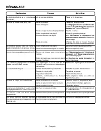
Page 54 - DÉPANNAGE; PROCÉDURES DE COUPE
4 − Français ou ces instructions utiliser l’outil. Dans les mains de personnes n’ayant pas reçu des instructions adéquates, les outils sont dangereux. Entretenir les outils motorisés et accessoires. Vérifier qu’aucune pièce mobile n’est mal alignée ou bloquée, qu’aucune pièce n’est brisée et s’ass...
Page 55 - RÈGLES DE SÉCURITÉ SCIE À TABLE; REBOND
5 − Français RÈGLES DE SÉCURITÉ SCIE À TABLE levée » provoque un mauvais alignement, du grippage et un rebond. Ne jamais tenter de passer autour ou par-dessus une lame qui tourne. Tenter d’atteindre la pièce à travailler ainsi peut provoquer un contact accidentel avec la lame en mouvement. Assur...
Page 58 - DOUBLE ISOLATION; une alimentation 120 V,; FICHES POLARISÉES; Longueur; FICHE
8 − Français ELECTRICAL DOUBLE ISOLATION La double isolation est un dispositif de sécurité utilisé sur les outils à moteur électriques, éliminant le besoin de cordon d’alimentation habituel à trois fils avec terre. Toutes les pièces métalliques exposées sont isolées des composants internes du moteur...
Page 59 - GLOSSAIRE
9 − Français GLOSSAIRE Trou pilote (perceuses à colonne et scie à découper) Petit trou pratiqué dans une pièce servant de guide pour assurer la précision d’un trou de plus grand diamètre ou pour l’insertion d’une lame de scie à découper. Blocs poussoirs (dégauchisseuses/raboteuses) Dispositifs utili...
Page 60 - CARACTÉRISTIQUES; FICHE TECHNIQUE
10 − Français 9 8 7 6 5 4 3 2 1 0 0 1 2 3 4 5 6 7 8 9 10 11 12 13 14 0 45 CARACTÉRISTIQUES FICHE TECHNIQUE Axe de lame ................................................16 mm (5/8 po)Diamètre de la lame................................... 254 mm (10 po)Inclinaison biseau ..................................
Page 61 - POUR SE FAMILIARISER AVEC LA SCIE À
11 − Français CARACTÉRISTIQUES POUR SE FAMILIARISER AVEC LA SCIE À TABLE Voir les figures 2 et 3. L’utilisation sûre de ce produit exige une compréhension des renseignements figurant sur l’outil et contenus dans le manuel d’utilisation, ainsi qu’une bonne connaissance du projet entrepris. Avant d’es...
Page 62 - COMPOSANTS FONCTIONNELS; ENSEMBLE DE COMMUTATEUR; COMMUTATEUR EN POSITION VERROUILLÉE
12 − Français CARACTÉRISTIQUES GUIDE LONGITUDINAL - Un robuste guide métallique, verrouillé par une poignée, guide la pièce à couper. Des rainures s’étendent sur le haut et les côtés du guide longitudinal pour permettre l’utilisation de serre-joints et d’accessoires optionnels. NOTE : Le guide infér...
Page 63 - OUTILS NÉCESSAIRES; ÉQUERRE DE CHARPENTIER
13 − Français OUTILS NÉCESSAIRES Les outils suivants (non inclus ou dessiné pour escalader) sont nécessaires pour l’assemblage et les réglages : Fig. 5 ÉQUERRE DE CHARPENTIER TOURNEVIS PHILLIPS ÉQUERRE COMBINÉE CLÉS A MOLETTE SERRE-JOINTS
Page 64 - LISTE DES PIÈCES DÉTACHÉES
14 − Français LISTE DES PIÈCES DÉTACHÉES Les composants suivants sont inclus avec votre scie à table : Fig. 6 A B C D A. Griffes antirebond ..............................................................1B. Guide longitudinal .............................................................1C. Protège-la...
Page 65 - ASSEMBLAGE; DÉBALLAGE; TROUS DE FIXATION
15 − Français ASSEMBLAGE DÉBALLAGE Ce produit doit être assemblé. Sortir la scie du carton avec précaution et la poser une un plan de travail stable. AVERTISSEMENT : Ne pas utiliser le produit si, en le déballant, vous constatez que des éléments figurant dans la Liste des pièces détachées sont déj...
Page 66 - ASSEMBLAGE DE STAND
16 − Français ASSEMBLAGE ASSEMBLAGE DE STAND Voir les figures 7 à 10. NOTE : Ne pas se stand à un usage autre que celui pour lequel il est conçu. Positionner les ferrures de support intérieure et extérieure de telle sorte à former un « X », comme il est illustré ci-après. Aligner les trous pour in...
Page 67 - LOQUET
17 − Français ASSEMBLAGE MONTAGE DU SUPPORT SUR LA STAND DE LA SCIE Voir les figures 11 et 12. AVERTISSEMENT : Ne soulevez pas la scie sans l’aide d’une autre personne. La scie pèse environ 55 lb. Tenez-la près de votre corps, pliez les genoux et soulevez-la avec les jambes, et non pas avec le dos. ...
Page 69 - LEVIER DE
19 − Français ASSEMBLAGE POUR CHANGER ENTRE UNE COUTEAU DIVISEUR Voir la figure 15. Cette scie est expédiée avec le couteau diviseur placé en la position « bas » pour les coupes de non traversante et doit être placé en la position « haut » pour autres opérations de coupe. ATTENTION : Faire preuve de...
Page 70 - POUR VÉRIFIER L’INSTALLATION DE LA LAME
20 − Français ASSEMBLAGE POUR VÉRIFIER L’INSTALLATION DE LA LAME Voir la figure 16. AVIS : Pour fonctionner correctement, les dents de la lame de scie doivent être orientées vers le bas et le devant de la scie. Le non respect de cet avertissement pourrait causer un dommage à la lame, la scie, ou la ...
Page 74 - UTILISATION; CAUSES DE REBOND
24 − Français UTILISATION AVERTISSEMENT : Ne pas laisser la familiarité avec les outils faire oublier la prudence. Ne pas oublier qu’une fraction de seconde d’inattention peut entraîner des blessures graves. AVERTISSEMENT : Toujours porter une protection oculaire certifiée conforme à la norme ANSI Z...
Page 75 - CONSEILS DE COUPE
25 − Français UTILISATION Nettoyer la scie, le protège-lame, sous la plaque à gorge, et n’importe quels sciure où n’importe quelle poussière de scie ou les pièces de fragment peuvent rassembler. Maintenir le protège-lame, le couteau diviseur et les griffes antirebond en place et en bon état. Le ...
Page 76 - SUPPORTS DE LA PIÈCE À TRAVAILLER
26 − Français UTILISATION SUPPORTS DE LA PIÈCE À TRAVAILLER Voir la figure 29. En coupant avec votre scie à table, veiller à ce que la pièce à couper soit correctement soutenue. Bien soutenir la pièce à travailler lors de la découpe permet non seulement d’améliorer la précision de coupe, mais aussi ...
Page 77 - COMMENT FABRIQUER UNE CALE-GUIDE; COMMENT INSTALLER UNE CALE-GUIDE; BLOC
27 − Français UTILISATION Pour utiliser sauteuse: Disposer la pièce plate sur la table avec l’éclat de bord contre la sauteuse et contre buteé. L’avoir la poignée de sauteuse et l’utilisation d’un bâton poussoir et/ou de bloc poussoir, voir ci-après la partie Coupe longitudinale dans cette secti...
Page 78 - TYPES DE COUPE; COUPE LONGITUDINALE EN BISEAU
28 − Français UTILISATION TYPES DE COUPE Voir la figure 34. Il y a six principaux types de coupe : 1) coupe transversale, 2) coupe longitudinale, 3) coupe d’onglet, 4) coupe transversale en biseau, 5) coupe en long en biseau et 6) coupe d’onglet composé (en biseau). Toutes les autres coupes sont des...
Page 79 - RÉGLAGE DE LA PROFONDEUR DE LAME
29 − Français LEVIER DE VERROUILLAGE DE BISEAU LEVIER DE VERROUILLAGE DE BISEAU UTILISATION RÉGLAGE DE LA PROFONDEUR DE LAME Voir la figure 35 et 36. La profondeur de coupe doit être réglée pour que les pointes extérieurs des dents de la lame dépassent la pièce de bois d’environ 3 à 6 mm (1/8 à 1/4 ...
Page 80 - POUR UTILISER LE GUIDE LONGITUDINAL
30 − Français UTILISATION POUR UTILISER LE GUIDE LONGITUDINAL Voir les figures 38 et 39. AVERTISSEMENT : Pour réduire le risque de blessures, toujours vérifier que le guide longitudinal est parallèle à la lame avant de commencer une coupe. NOTE: Le guide longitudinal fourni avec la scie possède un g...
Page 81 - POUR UTILISER LE GUIDE À ONGLET
31 − Français UTILISATION NOTE : Positionner le guide inférieur de sorte qu’il soit orienté loin de la lame. Desserrer la vis de l’indicateur et placer ce dernier sur la graduation 51 mm (2 po), comme illustré. Resserrer la vis, puis vérifier la dimension et la position du guide longitudinal. NO...
Page 83 - EXÉCUTION DE COUPES
33 − Français VIS UTILISATION Si les distances mesurées sont différentes : Retirer la garde de lame, le couteau diviseur et griffes antirebond. Relever la lame au maximum en tournant le volant de réglage de hauteur / biseau. Desserrez d’un demi-tour les vis extérieure; ceci per-mettra au mécanis...
Page 84 - COUPE TRANSVERSALE
34 − Français UTILISATION Lors de la coupe, toujours placer la pièce à travailler contre la face du guide à onglet. Pour empêcher la pièce à travailler de bouger, attacher un morceau de papier abrasif sur la face du guide à onglet. NOTE : Il est recommandé de placer la pièce à conserver sur le même ...
Page 85 - COUPE LONGITUDINALE
35 − Français UTILISATION Pour effectuer des coupes transversales répétitives : Un bloc d’arrêt peut servir comme guide d’arrêt pour réaliser des coupes transversales répétitives de même longueur sans avoir à marquer la pièce à travailler pour chaque coupe. L’extrémité d’un bloc d’arrêt doit toujour...
Page 87 - COUPE D’ONGLET
37 − Français UTILISATION COUPE D’ONGLET Voir la figure 51. AVERTISSEMENT : Afin d’éviter le risque de blessures graves, s’assurer que la garde de lame est installée et fonctionne correctement. Régler la lame sur la profondeur de coupe correcte pour la pièce. Retirer le guide longitudinal. Rég...
Page 89 - PLACER LA MAIN GAUCHE
39 − Français UTILISATION COUPE D’ONGLET COMPOSÉ (EN BISEAU) Voir la figure 55. AVERTISSEMENT : Afin d’éviter le risque de blessures graves, s’assurer que la garde de lame est installée et fonctionne correctement. AVERTISSEMENT : Pour éviter de coincer le bois et causer un rebond, le guide d’onglet ...
Page 90 - COUPE D’UNE PIÈCE DE GRANDE TAILLE
40 − Français UTILISATION COUPE D’UNE PIÈCE DE GRANDE TAILLE Voir la figure 56. S’assurer que la scie est solidement assujettie sur le plan de travail, afin que le poids d’une grande planche ne risque pas de la faire basculer. AVERTISSEMENT : Afin d’éviter le risque de blessures graves, s’assurer qu...
Page 91 - COUPE NON TRAVERSANTE; GARDE DE
41 − Français UTILISATION COUPE NON TRAVERSANTE Voir la figure 57. Les coupes non traversantes (a fait avec une norme lame de 10 po) peuvent être effectuées avec le grain (longitudinale) ou contre le grain (transversale). L’utilisation d’une coupe non transversante est essentielle pour couper les ra...
Page 92 - EXÉCUTION D’UN RAINAGE; LAME GARDE
42 − Français UTILISATION EXÉCUTION D’UN RAINAGE Voir la figure 58. Une plaque à gorge spéciale en option est requise pour cette procédure (voir la section Accessoires de ce manuel et consulter le magasin le plus proche). Toutes les lames standard, à rainer et moulurer doivent présenter une vitesse ...
Page 93 - RÉGLAGES; REMPLACEMENT DE LA LAME
43 − Français RÉGLAGES AVERTISSEMENT : Avant d’effectuer tout réglage, s’assurer que l’outil est débranché et le bouton supérieur du commutateur n’est pas enfoncé. Le non-respect de cet avertissement pourrait entraîner des blessures graves. Pour éviter des ajustements inutiles, il est bon de vérifie...
Page 94 - RÉGLAGE DE LA LAME À 0 ET 45°; ̊ VIS DE
44 − Français RÉGLAGES RÉGLAGE DE LA LAME À 0 ET 45° Voir les figures 61 et 62. La scie a été réglée en usine et, à moins qu’elle ait été endommagée en cours de transport, aucun réglage ne devrait être nécessaire. Après un usage prolongé, il peut être nécessaire de vérifier les réglages. Débranche...
Page 95 - RÉGLAGE DU GUIDE D’ONGLET
45 − Français RÉGLAGES Dès que la lame est à 45° de la table : Vérifier l’indicateur de biseau. Si l’indicateur n’indique pas la marque 45º sur le rapporteur d’angle de biseau, desserrer les vis d’ajustement de l’indicateur et ajustez l’indicateur. Resserrer les vis. Quand tous les ajustements...
Page 97 - VÉRIFICATION DE RALLONGE DE TABLE
47 − Français RÉGLAGES POUR AJUSTER LE LEVIER DE VERROUILLAGE DE LA COUPE EN BISEAU Voir la figure 68. Relâcher le levier de verrouillage de la coupe en biseau et la lame en biseau à 45˚. Appuyer sur le levier de verrouillage de la coupe en biseau pour bloquer la lame. An appliquant une force ...
Page 98 - ENTRETIEN; ENTRETIEN GÉNÉRAL; LUBRIFICATION; PLAQUES
48 − Français ENTRETIEN AVERTISSEMENT : Utiliser exclusivement des pièces d’origine pour les réparations. L’usage de toute autre pièce pourrait créer une situation dangereuse ou endommager l’outil. AVERTISSEMENT : Toujours porter une protection oculaire certifiée conforme à la norme ANSI Z87.1 lors ...
Page 99 - NETTOYER LE CHUTE À COPEAUX
49 − Français ENTRETIEN NETTOYER LE CHUTE À COPEAUX Voir la figure 72. Cette scie comprend une chute à copeaux utile pour débarrasser la sciure. Un aspirateur d’atelier ordinaire peut être fixé à la chute, située sous le dessous de la scie.Pendant des périodes d’utilisation prolongée, la chute à cop...
Page 100 - REMPLACEMENT DU BALAIS; Problème
50 − Français DÉPANNAGE ACCESSOIRES Rechercher ces accessoires où vous avez acheté ce produit ou en appelant au 1-866-539-1710 : Plaque à gorge pour lame à rainer ......................................................................................................................... 089240028701 ...
Page 102 - GARANTIE; RÉPARATIONS SOUS GARANTIE
52 − Français GARANTIE Une preuve d’achat doit être présentée pour toute demande de réparation sous garantie. Cette garantie se limite aux outils électriques à main et d’établi RIDGID ® achetés à partir du 1/2/04. Ce produit est fabriqué par One World Technologies, Inc., sous licence de marque de RI...
Page 103 - ÁREA DE TRABAJO; SEGURIDAD ELÉCTRICA; REGLAS DE SEGURIDAD GENERALES; EMPLEO Y CUIDADO DE LA HERRAMIENTA
3 − Español ADVERTENCIA: L e a t o d a s l a s a d v e r t e n c i a s , i n s t r u c c i o n e s , ilustraciones y especificaciones proporcionadas con esta herramienta eléctrica. No seguir las instrucciones indicadas a continuación puede provocar descargas eléctricas, incendios o lesiones graves. ...
Page 104 - SERVICIO; PROCEDIMIENTOS DE CORTE
4 − Español que la reparen antes de usarla. Numerosos accidentes son causados por herramientas eléctricas mal cuidadas. Mantenga las herramientas de corte afiladas y limpias. Las herramientas de corte bien cuidadas y con bordes bien afilados, tienen menos probabilidad de atascarse en la pieza de t...
Page 105 - REGLAS DE SEGURIDAD SIERRA DE MESA; CONTRAGOLPE
5 − Español REGLAS DE SEGURIDAD SIERRA DE MESA Proporcione apoyo auxiliar para la pieza de trabajo en la parte trasera y los laterales de la mesa de la sierra cuando corte piezas largas o anchas, a fin de mantenerlas niveladas. Las piezas de trabajo largas o anchas tienden a pivotar con el borde d...
Page 107 - SÍMBOLOS
7 − Español SÍMBOLOS Es posible que se empleen en esta herramienta algunos de los siguientes símbolos. Le suplicamos estudiarlos y aprender su significado. Una correcta interpretación de estos símbolos le permitirá utilizar mejor y de manera más segura la herramienta. SÍMBOLO NOMBRE DENOMINACIÓN/EXP...
Page 108 - ASPECTOS ELÉCTRICOS; DOBLE AISLAMIENTO; un suministro; CLAVIJAS POLARIZADAS; Longitud
8 − Español Fig. 1 CLAVIJA POLARIZADA ASPECTOS ELÉCTRICOS DOBLE AISLAMIENTO El doble aislamiento es una característica de seguridad de las herramientas eléctricas, la cual elimina la necesidad de usar el típico cordón eléctrico de tres conductores con conexión a tierra. Todas las partes metálicas ex...
Page 109 - GLOSARIO DE TÉRMINOS
9 − Español GLOSARIO DE TÉRMINOS Trinquetes anticontragolpe (sierras radiales y de mesa) Es un dispositivo, el cual, cuando se instala y da mantenimiento correctamente, sirve para detener la pieza de trabajo para no ser lanzada hacia atrás, hacia la parte frontal la sierra durante una operación de c...
Page 110 - CARACTERÍSTICAS; ESPECIFICACIONES DEL PRODUCTO
10 − Español 9 8 7 6 5 4 3 2 1 0 0 1 2 3 4 5 6 7 8 9 10 11 12 13 14 0 45 CARACTERÍSTICAS ESPECIFICACIONES DEL PRODUCTO Árbol de la hoja de corte ........................ 16 mm (5/8 pulg.)Diámetro de la hoja ............................... 254 mm (10 pulg.)Inclinación de la hoja ........................
Page 111 - FAMILIARÍCESE CON LA SIERRA DE MESA
11 − Español CARACTERÍSTICAS FAMILIARÍCESE CON LA SIERRA DE MESA Vea las figuras 2 y 3. El uso seguro que este producto requiere la comprensión de la información impresa en la herramienta y en el manual del operador así como ciertos conocimientos sobre el proyecto a realizar. Antes de usar este prod...
Page 112 - COMPONENTES EMPLEADOS EN EL MANEJO; CONJUNTO DEL INTERRUPTOR; INTERRUPTOR EN
12 − Español CARACTERÍSTICAS GUÍA DE CORTE AL HILO - Es una resistente guía metálica que sirve de apoyo a la pieza de trabajo y se fija con la manija de bloqueo. Las ranuras están colocadas a lo largo de la parte superior y en los lados de la guía de corte al hilo para permitir el uso de mordazas (p...
Page 113 - HERRAMIENTAS NECESARIAS
13 − Español HERRAMIENTAS NECESARIAS Se necesitan las siguientes herramientas (no incluido o dibujado para escalar) para el armado y la alineación: Fig. 5 ESCUADRA DE CARPINTERO DESTORNILLADOR PHILLIPS ESCUADRA DE COMBINACIÓN LLAVES AJUSTABLES PRENSAS EN C
Page 114 - PIEZAS SUELTAS
14 − Español PIEZAS SUELTAS Con la sierra de mesa vienen incluidos los siguientes artículos: Fig. 6 A B C D A. Trinquetes anticontragolpe ..................................................... 1 B. Guía de corte al hilo ............................................................... 1 C. Protección d...
Page 115 - ARMADO; DESEMPAQUETADO; AGUJEROS DE MONTAJE
15 − Español ARMADO DESEMPAQUETADO Este producto requiere armarse. Levante cuidadosamente de la caja la sierra y colóquela sobre una superficie de trabajo nivelada. ADVERTENCIA: No utilice este producto si alguna pieza incluida en la lista de piezas sueltas ya está ensamblada al producto cuando lo...
Page 116 - ARMADO DE PEDESTAL
16 − Español ARMADO ARMADO DE PEDESTAL Vea las figuras 7 a 10. NOTA: No use este pedestal de patas con otros equipos ni para otros propósitos. Coloque los soportes de apoyo interno y externo como se muestra a continuación de modo que formen una “X”. Alinee los orificios para las piezas de ferreter...
Page 117 - PESTILLO
17 − Español ARMADO MONTAJE DEL PEDESTAL CON PATAS EN LA BASE DE LA SIERRA DE MESA Vea las figuras 11 y 12. ADVERTENCIA: No levante la sierra sin tener ayuda. De la sierra pesa aproximadamente 55 libras. Manténgala cerca de su cuerpo. Mantenga sus rodillas dobladas y levante con sus piernas, no con ...
Page 118 - DE LA GARGANTA
18 − Español PARA RETIRAR/INSTALAR/ALINEAR LA PLACA DE LA GARGANTA Vea las figuras 13 y 14. ADVERTENCIA: Si la placa de la garganta está demasiado alta o demasiado baja, es posible que la pieza de trabajo se enganche en los bordes desiguales, lo que puede resultar en atascos o contragolpes que podrí...
Page 119 - PALANCA DE
19 − Español ARMADO PARA CAMBIAR POSICIÓN UN CUCHILLA SEPARADORA Vea la figura 15. La sierra es enviado con el cuchilla separadora colocó en la posición “abajo” para cortes no pasante y debe estar ser colocado en la posición “arriba” para todas las otras operaciones de cortes. PRECAUCIÓN: Tenga cuid...
Page 120 - PARA REVISAR LA INSTALACIÓN DE LA HOJA
20 − Español ARMADO PARA REVISAR LA INSTALACIÓN DE LA HOJA DE LA SIERRA Vea la figura 16. AVISO: Para funcionar correctamente, los dientes de la hoja deben apuntar hacia la parte frontal de la sierra, hacia abajo. De lo contrario podrían causarse daños a la hoja, a la sierra o a la pieza de trabajo....
Page 121 - PARA INSTALAR EL TRANQUETES ANTI-
21 − Español ARMADO PARA INSTALAR EL TRANQUETES ANTI- CONTRAGOLPE Y PROTECCIÓN DE LA HOJA Vea las figuras 17 a 19. ADVERTENCIA: Instale siempre la protección de la hoja y las garras que no permiten el retroceso en la cuchilla separadora en la posición “ascendente” para suministrar una cobertura de h...
Page 123 - ALMACENAMIENTO DE ACCESORIOS DE LA
23 − Español ARMADO ALMACENAMIENTO DE ACCESORIOS DE LA SIERRA DE MESA Vea las figuras 22 - 26. Cuando no estén en uso, la guía de corte al hilo, la cuchilla separadora, las llaves, la protección de la hoja, el medidor de inglete, los trinquetes anticontragolpe y el palo empujador pueden guardarse de...
Page 124 - FUNCIONAMIENTO; APLICACIONES; CAUSAS DE LOS CONTRAGOLPES
24 − Español FUNCIONAMIENTO ADVERTENCIA: No permita que su familarización con las herramientas lo vuelva descuidado. Tenga presente que un descuido de un instante es suficiente para causar una lesión grave. ADVERTENCIA: Siempre póngase protección ocular con la marca de cumplimiento de la norma ANSI ...
Page 125 - AYUDAS PARA CORTAR
25 − Español FUNCIONAMIENTO Mantenga la protección de la hoja, la cuchilla separadora y los trinquetes anticontragolpe en su lugar y en un estado de funcionamiento apropiado. La cuchilla separadora debe estar alineada con la hoja y los trinquetes anticontragolpe deben detener un contragolpe una ve...
Page 126 - SOPORTES DE LA PIEZA DE TRABAJO
26 − Español FUNCIONAMIENTO SOPORTES DE LA PIEZA DE TRABAJO Vea la figura 29. Cuando corte con la sierra de mesa, asegúrese de que la pieza de trabajo esté bien sujetada. El soporte adecuado de la pieza de trabajo durante el proceso de corte no solo mejora la precisión del corte, sino que también pe...
Page 127 - PEINES DE SUJECIÓN; FORMA DE MONTAR UN PEINE DE SUJECIÓN; BLOQUES
27 − Español FUNCIONAMIENTO Para utilizar vaivén: Posicione el pieza de trabajo plano sobre la mesa con el rubor de orilla contra la vaivén y contra la tope. Tener el mango de vaivén y utilizar un palos empujadora y/o bloque empujador, consulte Cómo efectuar cortes al hilo más adelante en esta s...
Page 128 - TIPOS DE CORTES; CORTE AL HILO EN BISEL
28 − Español FUNCIONAMIENTO TIPOS DE CORTES Vea la figura 34. Hay seis cortes básicos: 1) el corte transversal, 2) el corte al hilo, 3) el corte a inglete, 4) el corte transversal en bisel, 5) el corte al hilo en bisel y 6) el corte a inglete combinado (en bisel). Todos los otros cortes son combinac...
Page 129 - PARA AJUSTAR EL INDICADOR DE BISEL
29 − Español FUNCIONAMIENTO PARA CAMBIAR LA PROFUNDIDAD DE LA HOJA Vea la figura 35 y 36. Se debe ajustar la profundidad de la hoja de la sierra de manera que las puntas exteriores de la hoja queden más elevadas que la pieza de trabajo de 3,2 a 6,4 mm (1/8 pulg. a 1/4 pulg.) aproximadamente, pero lo...
Page 130 - PARA USAR LA GUÍA DE CORTE AL HILO
30 − Español REBORDE TRASERO FUNCIONAMIENTO PARA USAR LA GUÍA DE CORTE AL HILO Vea las figuras 38 y 39. ADVERTENCIA: Para reducir el riesgo de sufrir lesiones, siempre asegúrese de que la guía de corte al hilo esté paralela a la hoja, antes de iniciar cualquier operación. NOTA: La guía de corte al h...
Page 131 - PARA USAR LA GUÍA DE INGLETES
31 − Español FUNCIONAMIENTO NOTA: Coloque la guía baja de manera que quede hacia fuera con respecto a la hoja. Afloje el tornillo del indicador de escala y alinea con la 51 mm (2 pulg.) marca como mostrado. Apriete el tornillo y verifique la dimensión y la guía de corte al hilo. NOTA: Cuando use...
Page 133 - FORMA DE EFECTUAR CORTES
33 − Español TORNILLOS FUNCIONAMIENTO Si ambas distancias medidas son diferentes: Retirar la protección de la hoja, el cuchilla separadora y trinquetes anti contragolpe. Eleve la hoja de la sierra; para ello, gire el volante de ajuste de altura y bisel. Afloje 1/2 vuelta los tornillos exterior; ...
Page 134 - CÓMO EFECTUAR CORTES TRANS-VERSALES
34 − Español FUNCIONAMIENTO CÓMO EFECTUAR CORTES TRANS-VERSALES Vea las figuras 46 a 48. ADVERTENCIA: A s e g ú re s e d e q u e e s t é i n s t a l a d o y f u n c i o n e adecuadamente el conjunto de protección de la hoja, para evitar posibles lesiones graves. ADVERTENCIA: El uso de la guía de cor...
Page 135 - CÓMO EFECTUAR CORTES AL HILO; CORTE TRANSVERSAL REPETITIVO
35 − Español FUNCIONAMIENTO Para realizar cortes transversales repetitivos, siga estos pasos: Se puede usar un bloque de detención como indicador de corte para realizar cortes transversales repetitivos de la misma longitud sin tener que marcar la pieza de trabajo para hacer cada corte. El extremo de...
Page 138 - CÓMO EFECTUAR CORTES AL HILO EN BISEL
38 − Español FUNCIONAMIENTO CÓMO EFECTUAR CORTES AL HILO EN BISEL Vea la figura 54. ADVERTENCIA: A s e g ú re s e d e q u e e s t é i n s t a l a d o y f u n c i o n e adecuadamente el conjunto de protección de la hoja para evitar lesiones graves. ADVERTENCIA: La guía de corte al hilo debe estar del...
Page 139 - COLOQUE LA MANO IZQUIERDA
39 − Español FUNCIONAMIENTO C Ó M O E F E C T U A R C O RT E S A I N G L E T E COMBINADOS (EN BISEL) Vea la figura 55. ADVERTENCIA: A s e g ú re s e d e q u e e s t é i n s t a l a d o y f u n c i o n e adecuadamente el conjunto de protección de la hoja para evitar posibles lesiones graves. ADVERTEN...
Page 140 - CÓMO CORTAR UN PANEL GRANDE
40 − Español FUNCIONAMIENTO CÓMO CORTAR UN PANEL GRANDE Vea la figura 56. Asegúrese de que la sierra esté debidamente asegurada a una superficie de trabajo para evitar cualquier volcamiento producido por un panel grande. ADVERTENCIA: A s e g ú re s e d e q u e e s t é i n s t a l a d o y f u n c i o...
Page 141 - CÓMO EFECTUAR UN CORTE SIN TRASPASO
41 − Español FUNCIONAMIENTO CÓMO EFECTUAR UN CORTE SIN TRASPASO Vea la figura 57. Pueden efectuarse cortes sin traspaso (hizo con un estándar 10 pulg. hoja) del espesor de la pieza de trabajo paralelos a la fibra de la madera (corte al hilo) o transversales a la fibra (corte transversal). El corte s...
Page 142 - CÓMO EFECTUAR CORTES DE RANURA; SIN LA
42 − Español FUNCIONAMIENTO CÓMO EFECTUAR CORTES DE RANURA Vea la figura 58. Para este procedimiento se requiere una placa de la garganta para corte de ranuras optativa (vea la sección Accesorios de este manual y consulte al personal de la tienda de menudeo de su preferencia). Todos las hojas y jueg...
Page 143 - AJUSTES; PARA REEMPLAZAR LA HOJA
43 − Español AJUSTES ADVERTENCIA: Antes de efectuar cualquier ajuste, asegúrese de que la herramienta esté desconectada del suministro de corriente y que el botón superior del interruptor no esté presionado. La falta de atención a esta advertencia podría causar lesiones corporales graves. Para evita...
Page 144 - PARA AJUSTAR LA HOJA DE CORTE A 0° O 45°; HOJA A 45 ̊ BISEL
44 − Español AJUSTES PARA AJUSTAR LA HOJA DE CORTE A 0° O 45° Vea las figuras 61 y 62. Los ajustes de ángulo de su sierra se hicieron en la fábrica y, a menos que se hayan dañado durante el transporte, no necesitan ajuste durante el armado. Después de un uso intenso, es posible que se necesite revis...
Page 145 - AJUSTE DEL GUÍA DE INGLETE
45 − Español AJUSTES BASE DEL GUÍA DE INGLETE TORNILLO DE PARADA AJUSTABLE A 45° CONTRATUERCA Fig. 63 PERILLA VARILLA DEL GUÍA DE INGLETE TORNILLO DE PARADA AJUSTABLE A 0° CLAVIJA DE PARADA Una vez que la hoja forme un ángulo de 45° con respecto a la mesa: Controle el indicador de bisel. Si el i...
Page 147 - CONTROL DE LA EXTENSIÓN DE LA MESA
47 − Español ACOPLAMIENTO HEXAGONAL AJUSTES PARA AJUSTAR LA PALANCA DE FIJACIÓN DE BISEL Vea la figura 68. Suelte la palanca de fijación de bisel y la hoja de la sierra del bisel a 45˚. Empuje la palanca de fijación de bisel para fijar la hoja en su lugar. Con fuerza moderada, intente mover el...
Page 148 - MANTENIMIENTO; MANTENIMIENTO GENERAL; LUBRICACION; PLACAS
48 − Español MANTENIMIENTO ADVERTENCIA: Al dar servicio a la unidad, sólo utilice piezas de repuesto idénticas. El empleo de piezas diferentes puede presentar un peligro o causar daños al producto. ADVERTENCIA: Siempre póngase protección ocular con la marca de cumplimiento de la norma ANSI Z87.1. Si...
Page 149 - LIMPIEZA DEL VERTEDERO DE ASERRÍN
49 − Español MANTENIMIENTO LIMPIEZA DEL VERTEDERO DE ASERRÍN Vea la figura 72. Esta sierra incluye un vertedero de aserrín práctico para descargar el aserrín. Puede conectar una aspiradora común al vertedero de aserrín, ubicado debajo de la parte trasera de la sierra.Durante períodos de uso prolonga...
Page 150 - CORRECCIÓN DE PROBLEMAS; Problema; ACCESORIOS; REEMPLAZO DE LAS ESCOBILLAS
50 − Español CORRECCIÓN DE PROBLEMAS Problema Causa Solución Vibración excesiva. Está desequilibrada la hoja.Está dañada la hoja.No está montada firmemente la hoja.Está desigual la superficie de trabajo. Está combada la hoja. Reemplace la hoja.Reemplace la hoja.Apriete todas las piezas.Coloque la pi...
Page 152 - GARANTÍA; POLÍTICA DE GARANTÍA DE SATISFACCIÓN
52 − Español GARANTÍA Debe presentarse prueba de la compra al solicitar servicio al amparo de la garantía. Se limita a las herramientas de mano y estacionarias RIDGID ® adquiridas a partir de 1/Feb./04. Este producto está manufacturado por One World Technologies, Inc., La licencia de uso de la marca...
Page 156 - OPERATOR’S MANUAL; Customer Service Information:; Información sobre servicio al consumidor:
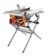
995000889 6-17-20 (REV:05) OPERATOR’S MANUAL MANUEL D’UTILISATIONMANUAL DEL OPERADOR 10 in. TABLE SAW SCIE À TABLE de 254 mm (10 po)SIERRA DE MESA de 254 mm (10 pulg.) R4518/R4518T ONE WORLD TECHNOLOGIES, INC. P.O. Box 1427Anderson, SC 29622 USA 1-866-539-1710 powertools.ridgid.com RIDGID is a reg...