Page 2 - Save all warnings and instructions for future reference.; WORK AREA SAFETY; Keep work area clean and well lit.; ELECTRICAL SAFETY; Do not expose power tools to rain or wet conditions.; GENERAL SAFETY RULES; PERSONAL SAFETY
2 - English WARNING: R e a d a l l s a f e t y w a r n i n g s , i n s t r u c t i o n s , illustrations and specifications provided with this power tool. Failure to follow all instructions listed below may result in electric shock, fire and/or serious injury. Save all warnings and instructions for ...
Page 3 - Keep cutting tools sharp and clean.; SERVICE; MITER SAW SAFETY RULES; the workpiece into the blade or cut ”freehand” in any; Cut only one workpiece at a time.
3 - English GENERAL SAFETY RULES Disconnect the plug from the power source and/or remove the battery pack, if detachable, from the power tool before making any adjustments, changing accessories, or storing power tools. Such preventive safety measures reduce the risk of starting the power tool acci...
Page 4 - ADDITIONAL SAFETY RULES
4 - English MITER SAW SAFETY RULES Provide adequate support such as table extensions, saw horses, etc. for a workpiece that is wider or longer than the table top. Workpieces longer or wider than the miter saw table can tip if not securely supported. If the cut-off piece or workpiece tips, it can l...
Page 6 - SYMBOLS; SYMBOL
6 - English SYMBOLS Some of the following symbols may be used on this tool. Please study them and learn their meaning. Proper interpretation of these symbols will allow you to operate the tool better and safer. SYMBOL NAME DESIGNATION/EXPLANATION Safety Alert Indicates a potential personal injury ha...
Page 7 - ELECTRICAL; DOUBLE INSULATION; ELECTRICAL CONNECTION; power supply that is 120 V, AC only (normal; EXTENSION CORDS; Cord Length
7 - English ELECTRICAL DOUBLE INSULATION Double insulation is a concept in safety in electric power tools, which eliminates the need for the usual three-wire grounded power cord. All exposed metal parts are isolated from the internal metal motor components with protecting insulation. Double insulate...
Page 8 - GLOSSARY OF TERMS
8 - English GLOSSARY OF TERMS Pilot Hole (drill presses and scroll saws) A small hole drilled in a workpiece that serves as a guide for drilling large holes accurately or for insertion of a scroll saw blade. Push Blocks (jointer planers) Device used to feed the workpiece over the jointer planer cutt...
Page 9 - FEATURES; PRODUCT SPECIFICATIONS
9 - English FEATURES PRODUCT SPECIFICATIONS Blade Diameter .......................................................... 12 in.Arbor Hole .................................................................... 1 in.No Load Speed ....................................... 4,000/min. (RPM)Input ..................
Page 10 - KNOW YOUR COMPOUND MITER SAW; BEVEL LOCK KNOB
10 - English FEATURES Fig. 2 SWITCH TRIGGER BEVEL LOCK KNOB BEVEL LOCK KNOB FENCE LOCK KNOB CARRYING HANDLE CARRYING HANDLE HEAD LOCK PIN BLADE WRENCH STORAGE DEPTH CONTROL KNOB BEVEL DETENT LEVER KNOW YOUR COMPOUND MITER SAW See Figures 1 - 2. The safe use of this product requires an understanding ...
Page 12 - OFF
12 - English SWITCH TRIGGER Fig. 6 FEATURES PADLOCK SELF-RETRACTING LOWER BLADE GUARD The lower blade guard is made of shock-resistant, see-through plastic that provides protection from each side of the blade. It retracts over the upper blade guard as the saw is lowered into the workpiece. SLIDE BAR...
Page 13 - TOOLS NEEDED; LOOSE PARTS
13 - English WARNING: The use of attachments or accessories not listed might be hazardous and could cause serious personal injury. The following tools (not included) are needed for making adjustments or installing the blade: COMBINATION SQUARE TOOLS NEEDED Fig. 7 COMBINATION WRENCH 8 mm, 10 mm, 13 m...
Page 14 - ASSEMBLY; UNPACKING
14 - English ASSEMBLY UNPACKING This product requires assembly. Carefully lift saw from the carton by the carrying handle and the saw base, and place it on a level work surface. WARNING: Do not use this product if any parts on the Loose Parts List are already assembled to your product when you unp...
Page 15 - MOUNTING HOLES; DUST BAG AND FRAME ASSEMBLY
15 - English ASSEMBLY WARNING: This saw can tip over if the saw head is released suddenly and the saw is not secured to a work surface. ALWAYS secure this saw to a stable work surface before any use to avoid serious personal injury. MOUNTING HOLES See Figure 9. WARNING: Before starting any cutting o...
Page 16 - USING THE DEPTH GUIDE; To use the depth guide:; LOCKING / UNLOCKING THE SAW ARM; To unlock and raise the saw arm:; BLADE WRENCH
16 - English ASSEMBLY USING THE DEPTH GUIDE See Figure 12. When used, the depth guide limits the downward travel of the blade when cutting dadoes and other non-through cuts. To use the depth guide: Unplug the saw. Rotate the depth stop outward. With the end of the depth control knob touching t...
Page 17 - INSTALLING / REPLACING THE BLADE; Do not
17 - English ASSEMBLY Fig. 14 INSTALLING / REPLACING THE BLADE See Figure 14. WARNING: A 12 in. blade is the maximum blade capacity of the saw. Never use a blade that is too thick to allow outer blade washer to engage with the flats on the arbor. Larger blades will come in contact with the blade gua...
Page 18 - INSTALLING THE WORK CLAMP; To install the work clamp:
18 - English ASSEMBLY Fig. 15 ADJUSTABLE THROAT PLATE BLADE WRENCH Fig. 16 WORK CLAMP WORK CLAMP SHAFT WORK CLAMP HOLE ADJUSTING/REMOVING/REPLACING THE ADJUSTABLE THROAT PLATE See Figure 15. When squaring the saw blade, it may be necessary to move the throat plate away from the blade. Once the saw’s...
Page 19 - To Make Extended Miter Cuts; SQUARING THE SAW BLADE TO THE FENCE
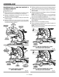
19 - English ASSEMBLY If the front or back edge of the saw blade angles away from the square as shown in figures 20 and 21, adjustments are needed. Rotate the extension tables to their fully extended position. See To Make Extended Miter Cuts later in this manual. SQUARING THE SAW BLADE TO THE FE...
Page 21 - SQUARING THE BLADE TO THE MITER TABLE
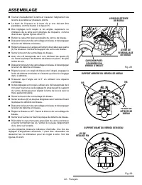
21 - English ASSEMBLY Fig. 25 CORRECT VIEW OF BLADE SQUARE WITH MITER TABLE VIEW OF BLADE NOT SQUARE WITH MITER TABLE, ADJUSTMENTS ARE REQUIRED Fig. 27 VIEW OF BLADE NOT SQUARE WITH MITER TABLE, ADJUSTMENTS ARE REQUIRED Fig. 26 SQUARING THE BLADE TO THE MITER TABLE See Figures 25 - 29. Unplug the ...
Page 23 - APPLICATIONS; OPERATION
23 - English WARNING: Do not allow familiarity with tools to make you careless. Remember that a careless fraction of a second is sufficient to inflict severe injury. WARNING: Always wear eye protection with side shields marked to comply with ANSI Z87.1. Failure to do so could result in objects being...
Page 24 - LED LIGHTING SYSTEM; LED; TO MAKE NON-SLIDING CUTS
24 - English OPERATION Fig. 30 CUTTING WITH YOUR SLIDING COMPOUND MITER SAW WARNING: When using a work clamp or C-clamp to secure your workpiece, clamp workpiece on one side of the blade only. The workpiece must remain free on one side of the blade to prevent the blade from binding in workpiece. The...
Page 25 - TO MITER CUT/CROSS CUT
25 - English Fig. 31 OPERATION WORK CLAMP SLIDE LOCK KNOB CROSS CUT TO MITER CUT/CROSS CUT See Figures 31 - 32. A cross cut is made by cutting across the grain of the workpiece. A straight cross cut is made with the miter table set at the 0 ° position. Miter cross cuts are made with the miter table ...
Page 26 - TO MAKE EXTENDED MITER CUTS
26 - English OPERATION TO MAKE EXTENDED MITER CUTS See Figures 33 - 35. The extended miter capacity of the saw allows you to make miter cuts up to 70 ° . Using the miter extension tables, you can cut 22.5° miters for acute 45° corners.The rotating extension tables can be set to one of three position...
Page 27 - TO BEVEL CUT
27 - English OPERATION Slowly lower the blade into and through the workpiece. Release the switch trigger and allow the saw blade to stop rotating before raising the blade out of workpiece and removing the workpiece from the miter table. TO BEVEL CUT See Figures 36 - 37. A bevel cut is made by cu...
Page 28 - TO COMPOUND MITER CUT; COMPOUND MITER CUT
28 - English TO COMPOUND MITER CUT See Figure 38. A compound miter cut is a cut made using a miter angle and a bevel angle at the same time. This type of cut is used to make picture frames, cut molding, make boxes with sloping sides, and for certain roof framing cuts. To make this type of cut the co...
Page 29 - SUPPORTING LONG WORKPIECES; TO SLIDE CUT; NEVER
29 - English OPERATION SUPPORTING LONG WORKPIECES See Figures 39 - 40. Long workpieces need extra supports. Supports, roller stand, or work surface level with the saw table should be placed along the workpiece so it does not sag. The support should let the workpiece lay flat on the base of the saw a...
Page 30 - MAKING AN AUXILIARY FENCE; MUST
30 - English of a board is placed against the fence, the board could collapse on the blade at the end of the cut, jamming the blade. See Figures 51 and 52. When cutting long pieces of lumber or molding, support the opposite end of the stock with a roller stand or with a work surface level with the...
Page 31 - ROUGH CUTTING A DADO
31 - English OPERATION ROUGH CUTTING A DADO See Figures 44 - 45. Using a wood chisel and the depth guide, it is possible to make a rough dado cut. The marks on the depth guide are to be used for reference only. Always make a practice cut on scrap wood. To use the depth guide: Unplug the saw. Rot...
Page 32 - CUTTING COMPOUND MITERS; PITCH
32 - English CUTTING COMPOUND MITERS To aid in making the correct settings, the compound angle setting chart below has been provided. Since compound cuts are the most difficult to accurately obtain, trial cuts should be made in scrap material, and much thought and planning made, prior to making your...
Page 33 - CUTTING CROWN MOLDING; Bevel
33 - English When cutting crown molding by this method, the bevel angle should be set at 33.85 ° . The miter angle should be set at 31.6 ° either right or left, depending on the desired cut for the application. See the chart below for correct angle settings and correct positioning of crown molding o...
Page 34 - (Crown Stops Sold Separately as an Accessory); REPOSITIONING THE SLIDING MITER FENCES
34 - English Fig. 47 Fig. 48 OPERATION Bevel Angle Type of Cut Setting Left side, inside corner1. Top edge of molding against fence2. Miter table set right 45 ° 3. Save left end of cut Right side, inside corner1. Bottom edge of molding against fence2. Miter table set left 45 ° 3. Save left end of cu...
Page 35 - CROWN AND BASEBOARD SETTING LEVER; To position for tall crown molding:
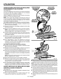
35 - English OPERATION CROWN AND BASEBOARD SETTING LEVER See Figure 49. The crown and baseboard setting lever is helpful when mak-ing miter cuts up to 45° for tall crown molding and vertical baseboard. Use the crown setting for tall crown molding of 4-5/8 in. and taller. NOTE: For cutting crown mold...
Page 36 - RIGHT; WIDE
36 - English CUTTING WARPED MATERIAL See Figures 51 - 52. When cutting warped material, always make sure it ispositioned on the miter table awith the convex side against the fence as shown in figure 51.If the warped material is positioned the wrong way as shown in figure 52, it will pinch the blade ...
Page 37 - ADJUSTMENTS; PIVOT ADJUSTMENTS; AUTHORIZED SERVICE CENTER.; TO ADJUST THE BEVEL PIVOT; AUTHORIZED SERVICE; ADJUSTING THE BEVEL LOCK
37 - English BEVEL LOCK KNOB CARRYING HANDLE DETENT ENGAGED BEVEL DETENT LEVER DETENT DISENGAGED TIGHTEN LOOSEN ADJUSTMENTS WARNING: Before performing any adjustment, make sure the tool is unplugged from the power supply. Failure to heed this warning could result in serious personal injury. The comp...
Page 38 - ADJUSTING THE MITER LOCK; To adjust the clamping force of the miter lock:
38 - English ADJUSTMENTS ADJUSTING THE MITER LOCK See Figures 56 - 57. Unplug the saw. Locate the miter lock nut, miter lock screw and miter lock shoe on the rear underside of the saw. To adjust the clamping force of the miter lock: Lift the miter lock lever and press the miter detent bypass...
Page 39 - ADJUSTING THE MITER LOCK LEVER
39 - English ADJUSTMENTS ADJUSTING THE MITER LOCK LEVER See Figure 58. Lift the miter lock lever to unlock the miter table. Unplug the saw. Lift the miter lock lever to unlock the miter table. If the miter lock lever is not parallel with the top of the miter table, adjustments are needed. Us...
Page 40 - MAINTENANCE; GENERAL MAINTENANCE; Proceed as follows when replacement is required:
40 - English MAINTENANCE WARNING: When servicing, use only identical replacement parts. Use of any other part may create a hazard or cause product damage. WARNING: Always wear eye protection with side shields marked to comply with ANSI Z87.1 during product operation. If operation is dusty, also wear...
Page 41 - CLEANING THE LED LENS; LED LENS
41 - English ACCESSORIES Look for these accessories where you purchased this product or call 1-866-539-1710: Miter Saw Utility Vehicle ........................................................................................................................................ AC9946 Dust Bag Assembly...
Page 42 - WARRANTY; RIDGID
42 - English WARRANTY Proof of purchase must be presented when requesting warranty service.Limited to RIDGID ® hand held and stationary power tools purchased 2/1/04 and after. This product is manufactured by TTI Consumer Power Tools, Inc. The trademark is licensed from RIDGID ® , Inc. All warranty c...
Page 43 - NOTES
Page 44 - SÉCURITÉ DU LIEU DE TRAVAIL; Garder le lieu de travail propre et bien éclairé.; SÉCURITÉ ÉLECTRIQUE; RÈGLES DE SÉCURITÉ GÉNÉRALES; SÉCURITÉ PERSONNELLE
2 - Français AVERTISSEMENT : Lire les avertissements de sécurité, les instructions et les précisions et consulter les illustrations fournis avec cet outil électrique. Le fait de ne pas se conformer à l’ensemble des consignes présentées ci-dessous risque d’entraîner des décharges électriques, un ince...
Page 45 - Garder les outils bien affûtés et propres.; DÉPANNAGE; RÈGLES DE SÉCURITÉ DU SCIE À ONGLETS
3 - Français RÈGLES DE SÉCURITÉ GÉNÉRALES UTILISATION ET ENTRETIEN DES OUTILS ÉLECTRIQUES Ne pas forcer l’outil. Utiliser l’outil approprié pour l’application. Un outil approprié exécutera le travail mieux et de façon moins dangereuse s’il est utilisé dans les limites prévues. Ne pas utiliser l’...
Page 46 - RÈGLES DE SÉCURITÉ SUPPLÉMENTAIRES
4 - Français RÈGLES DE SÉCURITÉ DU SCIE À ONGLETS de la lame de scie en rotation pendant la coupe. Il ne devrait pas y avoir de clous ou d’objets étrangers dans la pièce à travailler. Ne pas utiliser la scie jusqu’à ce que la table soit libre de tous les outils, déchets de bois, etc., à l’exceptio...
Page 48 - SYMBOLES
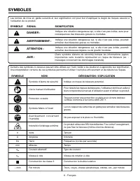
6 - Français SYMBOLES Certains des symboles ci-dessous peuvent être utilisés sur l’outil. Veiller à les étudier et à apprendre leur signification. Une interprétation correcte de ces symboles permettra d’utiliser l’outil plus efficacement et de réduire les risques. SYMBOLE NOM DÉSIGNATION / EXPLICATI...
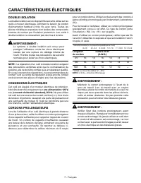
Page 49 - CARACTÉRISTIQUES ÉLECTRIQUES; DOUBLE ISOLATION; CONNEXIONS ÉLECTRIQUES; une alimentation 120 V,; CORDONS PROLONGATEURS; Longueur; AVERTISSEMENT
7 - Français CARACTÉRISTIQUES ÉLECTRIQUES DOUBLE ISOLATION La double isolation est un dispositif de sécurité utilisé sur les outils à moteur électriques, éliminant le besoin de cordon d’alimentation habituel à trois fils avec terre. Toutes les pièces métalliques exposées sont isolées des composants ...
Page 50 - GLOSSAIRE
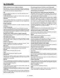
8 - Français GLOSSAIRE Trou pilote (perceuses à colonne et scie à découper) Petit trou pratiqué dans une pièce servant de guide pour assurer la précision d’un trou de plus grand diamètre ou pour l’insertion d’une lame de scie à découper. Blocs poussoirs (pour dégauchisseuses/raboteuses) Dispositifs ...
Page 51 - CARACTÉRISTIQUES; FICHE TECHNIQUE
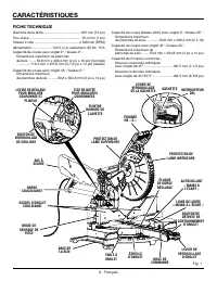
9 - Français CARACTÉRISTIQUES FICHE TECHNIQUE Diamètre de la lame........................................ 305 mm (12 po)Trou d’axe ........................................................ 25,4 mm (1 po)Vitesse à vide ................................................ 4 000/min (RPM) Alimentation ........
Page 52 - LEVIER DE DÉTENTE DE BISEAU; BOUTON DE VERROUILLAGE DE BISEAU
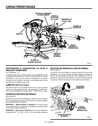
10 - Français CARACTÉRISTIQUES BOUTON DE COMMANDE DE PROFONDEUR GOUPILLE DE BLOCAGE DE LA TÊTE POIGNÉE DE TRANSPORT POIGNÉE DE TRANSPORT RANGEMENT DE CLÉ DE LAME BOUTON DE BLOCAGE DU GUIDE GÂCHETTE A P P R E N D R E À C O N N A Î T R E L A S C I E À ONGLETS COMPOSÉS Voir les figures 1 - 2. L’utilisa...
Page 53 - GOUPILLE DE VERROUILLAGE DE LA TÊTE
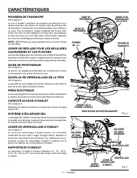
11 - Français CARACTÉRISTIQUES POIGNÉE DE TRANSPORT GOUPILLE DE VERROUILLAGE DE LA TÊTE GUIDE DE PROFONDEUR POIGNÉE EN « D » ENDROIT DE LA POIGNÉE LATÉRALE POIGNÉES DE TRANSPORT Voir la figure 4. La scie à onglets comprend une poignée de transport sur le dessus ainsi que des prises sur chaque côté d...
Page 54 - BARRE COULISSANTE
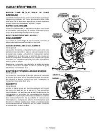
12 - Français CARACTÉRISTIQUES P R O T E C T I O N R É T R A C TA B L E D E L A M E INFÉRIEURE La protection de lame inférieure est construite dans un plastique transparent et résistant aux chocs qui couvre les deux côtés de la lame. Elle se rétracte sur la protection de lame supérieure lorsque la ...
Page 55 - OUTILS NÉCESSAIRES
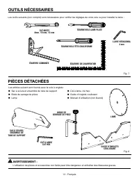
13 - Français AVERTISSEMENT : L’utilisation de pièces et accessoires non listés peut être dangereux et entraîner des blessures graves. Fig. 7 CLÉ MIXTE 8mm, 10 mm, 13 mm TOURNEVIS À LAME PLATE Les articles suivant sont fournis avec la scie à onglets : Sac à sciure et ensemble de tube de support ...
Page 56 - ASSEMBLAGE; DÉBALLAGE
14 - Français ASSEMBLAGE DÉBALLAGE Ce produit doit être assemblé. Sortir soigneusement la scie du carton en la tenant par la poignée de transport et la base de la scie, et la poser sur un plan de travail horizontal. AVERTISSEMENT : Ne pas utiliser le produit si, en le déballant, vous constatez que...
Page 57 - TROUS DE FIXATION
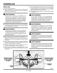
15 - Français ASSEMBLAGE AVERTISSEMENT : Cette scie peut basculer si sa tête est relâchée brusquement et assujettie à un plan de travail. Pour éviter des blessures graves, TOUJOURS assujettir la scie à un plan de travail stable. TROUS DE FIXATION Voir la figure 9. AVERTISSEMENT : Avant d’entrepren...
Page 58 - UTILISATION DU GUIDE DE PROFONDEUR; CLÉ DE LAME
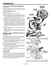
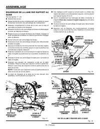
16 - Français ASSEMBLAGE UTILISATION DU GUIDE DE PROFONDEUR Voir la figure 12. Lorsqu’il est utilisé, le guide de profondeur limite la course vers le bas de la lame lors de la coupe de rainures et d’autres coupes non traversantes. Pour utiliser le guide de profondeur : Débrancher la scie. Tourne...
Page 59 - INSTALLATION/REMPLACEMENT DE LA LAME
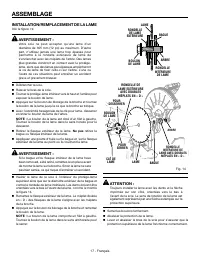
17 - Français ASSEMBLAGE INSTALLATION/REMPLACEMENT DE LA LAME Voir la figure 14. AVERTISSEMENT : Votre scie ne peut accepter qu’une lame d’un diamètre de 305 mm (12 po) au maximum. D’autre part, n’utilisez jamais une lame trop épaisse pour permettre à la rondelle extérieure de lame de s’enclencher a...
Page 60 - INSTALLATION DE LA BRIDE DE SERRAGE
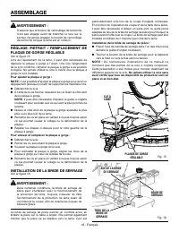
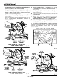
18 - Français ASSEMBLAGE Fig. 15 BRIDE DE SERRAGE AVERTISSEMENT : S’assurer que le bouton de verrouillage de la broche n’est pas engagé avant de brancher la scie sur le secteur. Ne jamais engager le bouton de verrouillage de la broche lorsque la lame est en rotation. RÉGLAGE /RETRAIT / REMPLACEMENT ...
Page 65 - UTILISATION
23 - Français AVERTISSEMENT : Le fait d’être familier avec les outils ne devrait faire oublier la prudence. Une fraction de seconde d’inattention suffit pour entraîner des blessures graves. AVERTISSEMENT : Toujours porter des lunettes de sécurité munies de protections latérales lors de l’utilisation...
Page 66 - SYSTÈME D’ÉCLAIRAGE DEL; INTERRUPTEUR
24 - Français UTILISATION Fig. 30 TRAVAUX DE COUPE AVEC LA SCIE À ONGLETS COMPOSÉS AVERTISSEMENT : Si un serre-joint ou une bride de serrage de pièce est utilisé pour maintenir la pièce, celui-ci ne doit être placé que d’un seul côté de la lame. La pièce doit être libre d’un côté de la lame pour emp...
Page 67 - POUR COUPES D’ONGLETS / TRANSVERSALES
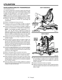
25 - Français UTILISATION POUR COUPES D’ONGLETS / TRANSVERSALES Voir les figures 31 et 32. La coupe est effectuée en travers du grain de la pièce de bois. Pour effectuer une coupe transversale droite, la table à onglet doit être réglée sur 0°. Les coupes d’onglets sont réalisées en réglant la table ...
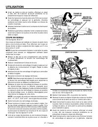
Page 69 - COUPE EN BISEAU
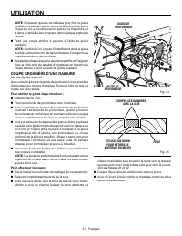
27 - Français UTILISATION Avant de mettre la scie en marche, effectuer un essai à vide, afin de s’assurer qu’aucun problème ne se présentera lorsque la coupe est effectuée. Saisir fermement le manche de la scie. Enfoncer le levier de verrouillage et appuyer sur la gâchette. ...
Page 70 - COUPE D’ONGLET COMPOSÉ
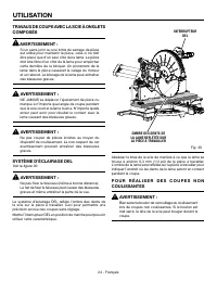
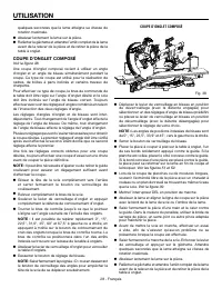
28 - Français quelques secondes que la lame atteigne sa vitesse de rotation maximale. Abaisser lentement la lame sur la pièce. Relâcher la gâchette et attendre l’arrêt complet de la lame avant de la relever de la pièce et de retirer la pièce de la table à onglet. COUPE D’ONGLET COMPOSÉ Voir...
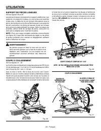
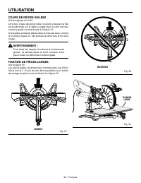
Page 71 - SUPPORT DE PIÈCES LONGUES; COUPE À COULISSEMENT; NE JAMAIS
29 - Français UTILISATION SUPPORT DE PIÈCES LONGUES Voir les figures 39 et 40. Les pièces longues nécessitent un support additionnel. Les supports, un support à rouleau, ou une surface de travail de niveau avec la table de la scie doivent être placés sous la pièce, de manière à ce qu’elle ne fléchis...
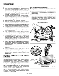
Page 72 - DOIT; Pour fixer le guide auxiliaire à la scie :
30 - Français Relever complètement le bras de la scie. Placer la pièce à couper à plat sur la table à onglet, l’un de ses bords solidement appuyé contre le guide. Si la planche est voilée, placer le côté convexe contre le guide. Si le bord concave d’une pièce est placé contre le guide, la pièc...
Page 73 - COUPE GROSSIÈRE D’UNE RAINURE
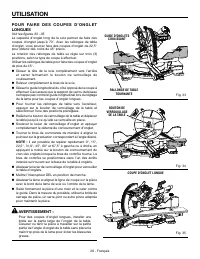
31 - Français UTILISATION NOTE : S’assurer que les vis utilisées pour fixer le guide auxiliaire ne passent pas à travers la face avant du guide et que les vis ne se retrouveront pas sur la trajectoire de la lame à cause de leur longueur, dans quelque angle que ce soit. Faire une coupe entière à ga...
Page 74 - COUPE D’ONGLETS COMPOSÉS; ANGLE DE
32 - Français UTILISATION COUPE D’ONGLETS COMPOSÉS Le tableau des réglages d’angles ci-dessous est conçu pour faciliter les réglages. Les coupes composées étant les plus difficiles à réaliser, des essais doivent être effectués sur des chutes et la coupe définitive ne doit être effectuée qu’après mûr...
Page 75 - COUPE DE MOULURE COURONNÉE; Type de coupe
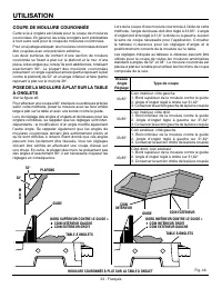
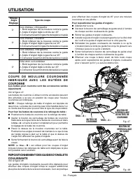
33 - Français UTILISATION Lors de la coupe d’une moulure couronnée à l’aide de cette méthode, l’angle de biseau doit être réglé à 33,85 °. L’angle d’onglet doit être réglé à 31,6° à droite ou à gauche, suivant le sens de coupe nécessaire pour l’application. Consulter le tableau ci-dessous pour les r...
Page 78 - CORRECT
36 - Français COUPE DE PIÈCES VOILÉES Voir les figures 51 et 52. Lors de la coupe de pièce voilée, toujours s’assurer qu’elle est positionnée sur la table à onglet avec le côté convexe contre le guide comme illustré à la figure 51.Si une pièce voilée est placée dans le mauvais sens, comme le montre ...
Page 79 - RÉGLAGES; RÉGLAGES DES PIVOTS; AUTHORIZED SERVICE CENTER; RÉGLAGE DU PIVOT DE BISEAU; CENTRE; RÉGLAGE DU VERROU DE BISEAU; PLAQUE DE
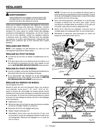
37 - Français RÉGLAGES AVERTISSEMENT : Avant d’effectuer tout réglage, s’assurer que l’outil est débranché. Le non respect de cet avertissement pourrait entraîner des blessures graves. Cette scie à onglets composés a été réglée en usine pour effectuer des coupes très précises. Toutefois, certains c...
Page 80 - Pour vérifier la force de serrage du verrou d’onglet :
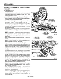
38 - Français RÉGLAGES RÉGLAGE DU LEVIER DE VERROUILLAGE D’ONGLET Voir les figures 56 et 57. Débrancher la scie. Localiser le contre-écrou à onglet, la vis de blocage à onglet et le sabot de verrouillage à onglet sur la face inférieure arrière de la scie. Pour vérifier la force de serrage du v...
Page 81 - RÉGLAGE DU BOUTON DE DÉTENTE D’ONGLET
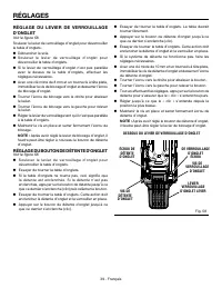
39 - Français RÉGLAGES RÉGLAGE DU LEVIER DE VERROUILLAGE D’ONGLET Voir le figure 58. Soulever le levier de verrouillage d’onglet pour déverrouiller la table d’onglets. Débrancher la scie. Soulever le levier de verrouillage d’onglet pour déverrouiller la table d’onglets. Si le levier de verro...
Page 82 - ENTRETIEN; ENTRETIEN GÉNÉRAL
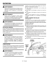
40 - Français ENTRETIEN AVERTISSEMENT : Utiliser exclusivement des pièces d’origine pour les réparations. L’usage de toute autre pièce pourrait créer une situation dangereuse ou endommager le produit. AVERTISSEMENT : Toujours porter une protection oculaire certifiée conforme à la norme ANSI Z87.1 lo...
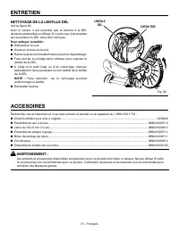
Page 83 - NETTOYAGE DE LA LENTILLE DEL; Pour nettoyer la lentille :; LENTILLE
41 - Français ACCESOIRES Rechercher ces accessoires où vous avez acheté ce produit ou en appelant au 1-866-539-1710 : Chariot utilitaire pour scie à onglets ...................................................................................................................... AC9946 Ensemble de...
Page 84 - GARANTIE; RÉPARATIONS SOUS GARANTIE; AUTRES LIMITATIONS
42 - Français GARANTIE Une preuve d’achat doit être présentée pour toute demande de réparation sous garantie.Cette garantie se limite aux outils électriques à main et d’établi RIDGID ® achetés à partir du 1/2/04. Ce produit est fabriqué par TTI Consumer Power Tools, Inc., sous licence de marque de...
Page 86 - ÁREA DE TRABAJO; Mantenga limpia y bien iluminada el área de trabajo.; SEGURIDAD ELÉCTRICA; REGLAS DE SEGURIDAD GENERALES; SEGURIDAD PERSONAL
2 - Español ADVERTENCIA: Lea todas las advertencias, instrucciones, ilustraciones y especificaciones proporcionadas con esta herramienta eléctrica. No seguir las instrucciones indicadas a continuación puede provocar descargas eléctricas, incendios o lesiones graves. Guarde todas las advertencias e i...
Page 87 - Mantenga las herramientas de corte afiladas y limpias.; SERVICIO; REGLAS DE SEGURIDAD DE LA SIERRA INGLETEADORA; de trabajo hacia la hoja o corte sin usar las manos
3 - Español REGLAS DE SEGURIDAD GENERALES manera más segura el trabajo, si además se maneja a la velocidad para la que está diseñada. No utilice la herramienta si el interruptor no enciende o no apaga. Cualquier herramienta eléctrica que no pueda controlarse con el interruptor es peligrosa y debe ...
Page 88 - Corte solo una pieza de trabajo por vez.; Guarde estas instrucciones.; Use un cordón de extensión adecuado.
4 - Español No use la hoja hasta que la mesa esté libre de cualquier otra herramienta, desechos de madera, etc. Solo debe estar la pieza de trabajo. En caso de haber desechos pequeños, piezas de manera sueltas o cualquier otro objeto que haga contacto con la hoja en movimiento, estos podrían salir...
Page 89 - ADVERTENCIAS DE SEGURIDAD ADICIONALES
5 - Español un electricista calificado para que instale una toma de corriente adecuada. No modifique la clavija de ninguna manera. Familiarícese con su herramienta eléctrica. Lea cuidadosamente el manual del operador. Aprenda los usos, limitaciones y posibles peligros relacionados con esta herrami...
Page 90 - SÍMBOLOS; SÍMBOLO
6 - Español SÍMBOLOS Es posible que se empleen en esta herramienta algunos de los siguientes símbolos. Le suplicamos estudiarlos y aprender su significado. Una correcta interpretación de estos símbolos le permitirá utilizar mejor y de manera más segura la herramienta. Alerta de seguridad Indica un p...
Page 91 - ASPECTOS ELÉCTRICOS; DOBLE AISLAMIENTO; CONEXIÓN ELÉCTRICA; un suministro; CORDONES DE EXTENSIÓN; Longitud
7 - Español ASPECTOS ELÉCTRICOS DOBLE AISLAMIENTO El doble aislamiento es una característica de seguridad de las herramientas eléctricas, la cual elimina la necesidad de usar el típico cordón eléctrico de tres conductores con conexión a tierra. Todas las partes metálicas expuestas están aisladas de ...
Page 92 - GLOSARIO DE TÉRMINOS
8 - Español GLOSARIO DE TÉRMINOS Este es un corte en el cual la hoja no corta la pieza de trabajo en dos pedazos. Agujero guía (taladradoras de columna y sierras caladoras) Es un agujero pequeño taladrado en una pieza de trabajo, el cual sirve como guía para taladrar con precisión agujeros más grand...
Page 93 - CARACTERÍSTICAS; ESPECIFICACIONES DEL PRODUCTO
9 - Español CARACTERÍSTICAS ESPECIFICACIONES DEL PRODUCTO Diámetro de la hoja .....................................305 mm (12 pulg.)Orificio del eje ...............................................25,4 mm (1 pulg.)Velocidad en vacío ....................................... 4 000/min. (RPM)Corriente de...
Page 94 - PALANCA DE RETENCIÓN DE BISEL; PERILLA DE FIJACIÓN DE BISEL
10 - Español CARACTERÍSTICAS Fig. 2 FAMILIARÍCESE CON LA SIERRA INGLETEADORA COMPUESTA Vea las figuras 1 - 2. El uso seguro que este producto requiere la comprensión de la información impresa en la herramienta y en el manual del operador así como ciertos conocimientos sobre el proyecto a realizar. A...
Page 95 - PALANCA DE SEGURIDAD DE INGLETE
11 - Español CARACTERÍSTICAS Fig. 4 MANGOS DE ACARREO Vea la figura 4. Por su conveniencia, al transportar la sierra de inglete de un lugar a otro, se proporciona un mango de transporte en la parte superior de la sierra junto con mangos a cada uno de los lados de la base de la sierra. Para transport...
Page 96 - GUÍAS TELESCÓPICA
12 - Español CARACTERÍSTICAS CANDADO PROTECCIÓN INFERIOR AUTORRETRAÍBLE DE LA HOJA La protección inferior de la hoja está hecha de plastico transparente resistente a impactos que proporciona protección a cada lado de la hoja. Se retrae por encima de la protección superior a medida que se baja la hoj...
Page 98 - ARMADO; DESEMPAQUETADO
14 - Español ARMADO DESEMPAQUETADO Este producto requiere armarse. Levante cuidadosamente de la caja la sierra sujetándola del mango de acarreo y de la base, y colóquela sobre una superficie de trabajo a nivel. ADVERTENCIA: No utilice este producto si alguna pieza incluida en la lista de piezas su...
Page 99 - AGUJEROS DE MONTAJE
15 - Español ARMADO ADVERTENCIA: Esta sierra puede volcarse si se suelta súbitamente la cabeza de la misma y la sierra no está asegurada a una superficie de trabajo. SIEMPRE asegure esta sierra a una superficie de trabajo estable antes de usarla para evitar lesiones serias. AGUJEROS DE MONTAJE Vea l...
Page 100 - USO DE LA GUÍA DE PROFUNDIDAD; LLAVE DE LA HOJA
16 - Español ARMADO NOTA : El orificio de escape también acepta una manguera de aspiración de 31,8 mm (1-1/4 pulg.) y adaptadores para aspiradoras en húmedo/seco de 31,8 mm (1-1/4 pulg.). USO DE LA GUÍA DE PROFUNDIDAD Vea la figura 12. Su uso limita el descenso de la hoja durante cortes de ranura y ...
Page 101 - PARA INSTALAR O REEMPLAZAR LA HOJA; HOJA
17 - Español ARMADO Fig. 14 PARA INSTALAR O REEMPLAZAR LA HOJA Vea la figura 14. ADVERTENCIA: La sierra tiene capacidad para hojas hasta de un diámetro de 305 mm (12 pulg.). Nunca utilice una hoja tan gruesa que la arandela exterior de la hoja no se enganche en las partes planas del árbol. Las hojas...
Page 102 - INSTALACIÓN DE LA PRENSA DE TRABAJO
18 - Español ARMADO LLAVE DE HOJA PRENSA DE TRABAJO AJUSTE/EXTRACCIÓN/REEMPLAZO DE LA PLACA DE GARGANTA AJUSTABLE Vea la figura 15. Al escuadrar la hoja de la sierra, puede ser necesario separar de la hoja la placa de garganta. Una vez que se haya confirmado la alineación de la sierra, devuelva la p...
Page 107 - FUNCIONAMIENTO
23 - Español ADVERTENCIA: N o p e r m i t a q u e s u f a m i l a r i z a c i ó n c o n l a s herramientas lo vuelva descuidado. Tenga presente que un descuido de un instante es suficiente para causar una lesión grave. ADVERTENCIA: Siempre póngase protección ocular con la marca de cumplimiento de la...
Page 108 - SISTEMA DE ILUMINACIÓN LED; INTERRUPTOR
24 - Español FUNCIONAMIENTO Fig. 30 F O R M A D E C O R TA R C O N L A S I E R R A INGLETEADORA COMBINADA ADVERTENCIA: Al utilizar la prensa de trabajo o una de mano para asegurar la pieza de trabajo, sujete ésta sólo en un lado de la hoja. La pieza de trabajo debe quedar libre en un lado de la hoja...
Page 109 - PA R A R E A L I Z A R C O RT E S D E I N G L E T E /
25 - Español FUNCIONAMIENTO PA R A R E A L I Z A R C O RT E S D E I N G L E T E / TRANSVERSALES Vea las figuras 31 y 32. Los cortes transversales se efectúan cortando a través de la veta de la pieza de trabajo. Un corte transversal recto se efectúa con la mesa de ingletes ajustada en la posición de ...
Page 111 - PARA CORTAR A BISEL
27 - Español Antes de encender la sierra, efectúe una simulación de la tarea de corte, sólo para asegurarse de que no suceda ningún problema durante la tarea de corte real. Sujete firmemente el mango de la sierra. Oprima el seguro del interruptor con el pulgar y luego oprima el gatillo. Deje tra...
Page 112 - PARA CORTAR INGLETES COMPUESTOS; CORTAR INGLETES COMPUESTOS
28 - Español Suelte el gatillo del interruptor y espere a que la hoja de la sierra deje de girar antes de levantarla de la pieza de trabajo y retirar la pieza de trabajo de la mesa de ingletes. PARA CORTAR INGLETES COMPUESTOS Vea la figura 38. Un corte de inglete compuesto es un corte empleando un...
Page 113 - NUNCA
29 - Español APOYE LAS PIEZAS DE TRABAJO LARGAS Vea las figuras 39 y 40. Las piezas de trabajo largas necesitan soportes extra. Los soportes base con ruedas, o superficie de trabajo nivelada con la sierra de mesa deben colocarse a lo largo de la pieza de trabajo de manera que no se pandee. El soport...
Page 114 - FORMA DE HACER UNA GUÍA AUXILIAR; DEBE
30 - Español guía. Si la tabla está doblada, coloque el canto convexo contra la guía. Si se coloca el canto cóncavo de la tabla contra la guía, la tabla podría venirse sobre la hoja al final del corte, atascándola. Vea las figuras 51 y 52. Al cortar tablas o molduras largas, apoye el extremo opues...
Page 115 - CORTE DE RANURAS BASTAS
31 - Español FUNCIONAMIENTO NOTA: Compruebe que la guía a auxiliar no interfiera con el protector inferior de la hoja. Corrija cualquier interferencia antes de proceder. Repita estos pasos con la segunda tabla alineándola con el lado derecho de las esquinas unidas de la mesa y haciendo un corte de...
Page 116 - CÓMO EFECTUAR CORTES A INGLETE COMBINADOS; AJUSTES DE ÁNGULOS COMBINADOS PARA ESTRUCTURAS COMUNES
32 - Español CÓMO EFECTUAR CORTES A INGLETE COMBINADOS Como ayuda para realizar los ajustes correctos, se suministra la siguiente tabla de ángulos combinados. Puesto que los cortes combinados son los más difíciles de obtener, deben efectuarse cortes de prueba en material de desecho, así como una gra...
Page 117 - CÓMO CORTAR MOLDURAS DE CORONA; Ajuste del
33 - Español FUNCIONAMIENTO Al cortar molduras de corona con este método, el ángulo de bisel debe fijarse a 33,9°. Puede usarse el control manual de bisel para lograr un ángulo de bisel de 33,9°. El ángulo de inglete debe fijarse a 31,6°, a la derecha o izquierda, según el corte deseado para cada ap...
Page 118 - Bisel
34 - Español FUNCIONAMIENTO CORTE DE ENCAJE DE MOLDURA DE CORONA UTILIZANDO TOPES DE CORONA (Los topes de corona se venden como accesorio por separado) Vea la figura 47. Los topes de corona se pueden comprar como accesorio de esta sierra para usar en cortes de molduras de corona en posición de encaj...
Page 120 - FORMA CORRECTA
36 - Español CÓMO CORTAR MATERIAL TORCIDO Vea las figuras 51 y 52. Al cortar material torcido, asegúrese siempre de que esté situado sobre la mesa de ingletes con el canto convexo apoyado contra la guía, como se muestra en la figura 51.Si se coloca de forma incorrecta como se muestra en la figura 52...
Page 121 - AJUSTES; AJUSTES DE LOS PIVOTES; AJUSTE DEL PIVOTE DE BISEL; CENTRO DE SERVICIO AUTORIZADO; AJUSTE DEL BLOQUEO DE BISEL
37 - Español AJUSTES ADVERTENCIA: Antes de efectuar cualquier ajuste, asegúrese de que la herramienta esté desconectada del suministro de corriente. La inobservancia de esta advertencia podría causar lesiones corporales serias. La sierra ingleteadora combinada ha sido ajustada en la fábrica para pro...
Page 122 - AJUSTE DE LA PALANCA DE FIJACIÓN DEL; To adjust miter table movement:
38 - Español AJUSTES AJUSTE DE LA PALANCA DE FIJACIÓN DEL INGLETE Vea las figuras 56 y 57. Desenchufe la sierra. Localice la tuerca de seguridad del inglete, el tornillo de fijación de ingletes y la zapata de fijación de ingletes en la parte inferior trasera de la sierra. Para verificar la fue...
Page 123 - AJUSTE DE LA PALANCA DE SEGURIDAD DE
39 - Español AJUSTES AJUSTE DE LA PALANCA DE SEGURIDAD DE INGLETE Vea la figura 58. Levante la palanca de seguridad de inglete para desbloquear la mesa de ingletes. Desenchufe la sierra. Levante la palanca de seguridad de inglete para desbloquear la mesa de ingletes. Si la palanca de seguridad...
Page 124 - MANTENIMIENTO; MANTENIMIENTO GENERAL; Proceda como sigue cuando se requiera un reemplazo:
40 - Español MANTENIMIENTO ADVERTENCIA: Al dar servicio a la unidad, utilice sólo piezas de repuesto idénticas. El empleo de piezas diferentes puede presentar un peligro o causar daños al producto. ADVERTENCIA: Siempre póngase protección ocular con la marca de cumplimiento de la norma ANSI Z87.1. Si...
Page 125 - LIMPIEZA DE LA LENTE LED; Para limpiar la lente:; LENTE
41 - Español ACCESORIOS Busque estos accesorios donde adquirió este producto o llame al 1-866-539-1710: Carro de servicio para sierras ingleteadoras ......................................................................................................... AC9946 Conjunto del saco captapolvo ........
Page 126 - GARANTÍA
42 - Español GARANTÍA Debe presentarse prueba de la compra al solicitar servicio al amparo de la garantía.Se limita a las herramientas de mano y estacionarias RIDGID ® adquiridas a partir del 1 de febrero de 2004. Este producto está manufacturado por TTI Consumer Power Tools, Inc. La licencia de uso...
Page 127 - NOTAS
Page 128 - OPERATOR’S MANUAL; 2 in. SLIDING COMPOUND MITER SAW WITH LED; Customer Service Information:; Información sobre servicio al consumidor:
995000671 10-4-22 (REV:04) OPERATOR’S MANUAL MANUEL D’UTILISATIONMANUAL DEL OPERADOR 12 in. SLIDING COMPOUND MITER SAW WITH LED SCIE À ONGLETS COMBINÉS COULISSANTE DE 305 mm (12 po) AVEC DEL SIERRA INGLETEADORA COMPUESTA DESLIZANTE DE 305 mm (12 pulg.) CON LED R4222 TTI CONSUMER POWER TOOLS, INC. P....


 Ridgid 122XL Manual
 Ridgid 258 Manual
 Ridgid 300 Manual
 Ridgid 600 Manual
 Ridgid 690 Manual
 Ridgid 700 Manual
 Ridgid 902 Manual
 Ridgid 1210 Manual
 Ridgid 1233 Manual
 Ridgid 2032-OS Manual
 Ridgid AC9940 Manual
 Ridgid AC9944 Manual
 Ridgid AC99401 Manual