Page 2 - Save all warnings and instructions for future reference.; WORK AREA SAFETY; Keep work area clean and well lit.; ELECTRICAL SAFETY; Do not expose power tools to rain or wet conditions.; GENERAL SAFETY RULES; PERSONAL SAFETY
2 - English WARNING: R e a d a l l s a f e t y w a r n i n g s , i n s t r u c t i o n s , illustrations and specifications provided with this power tool. Failure to follow all instructions listed below may result in electric shock, fire and/or serious injury. Save all warnings and instructions for ...
Page 3 - Keep cutting tools sharp and clean.; SERVICE; MITER SAW SAFETY RULES; the workpiece into the blade or cut “freehand” in any; Cut only one workpiece at a time.
3 - English GENERAL SAFETY RULES Store idle power tools out of the reach of children and do not allow persons unfamiliar with the power tool or these instructions to operate the power tool. Power tools are dangerous in the hands of untrained users. Maintain power tools and accessories. Check for...
Page 4 - ADDITIONAL SAFETY RULES
4 - English MITER SAW SAFETY RULES Provide adequate support such as table extensions, saw horses, etc. for a workpiece that is wider or longer than the table top. Workpieces longer or wider than the miter saw table can tip if not securely supported. If the cut-off piece or workpiece tips, it can l...
Page 6 - SYMBOLS; SYMBOL
6 - English SYMBOLS Some of the following symbols may be used on this tool. Please study them and learn their meaning. Proper interpretation of these symbols will allow you to operate the tool better and safer. SYMBOL NAME DESIGNATION/EXPLANATION Safety Alert Indicates a potential personal injury ha...
Page 7 - ELECTRICAL; DOUBLE INSULATION; ELECTRICAL CONNECTION; power supply that is 120 V, AC only (normal; EXTENSION CORDS; Cord Length
7 - English ELECTRICAL DOUBLE INSULATION Double insulation is a concept in safety in electric power tools, which eliminates the need for the usual three-wire grounded power cord. All exposed metal parts are isolated from the internal metal motor components with protecting insulation. Double insulate...
Page 8 - GLOSSARY OF TERMS
8 - English GLOSSARY OF TERMS Pilot Hole (drill presses and scroll saws) A small hole drilled in a workpiece that serves as a guide for drilling large holes accurately or for insertion of a scroll saw blade. Push Blocks (jointer planers) Device used to feed the workpiece over the jointer planer cutt...
Page 9 - FEATURES; PRODUCT SPECIFICATIONS
9 - English FEATURES Fig. 1 DUST BAG UPPER BLADE GUARD LOWER BLADE GUARD MITER SCALE MITER TABLE SAW BASE SLIDING MITER FENCE “D” HANDLE CARRYING HANDLE SLIDING MITER FENCE “NO HANDS ZONE” LABEL “NO HANDS ZONE” BOUNDARY LINE CONTROL ARM MITER LOCK LEVER DETENT RELEASE BUTTON THROAT PLATE WORK CLAMP ...
Page 11 - OFF
11 - English FEATURES MITER LOCK LEVER See Figure 4. The miter lock lever securely locks the saw at the desired miter angle. Push the lever down to lock the saw in place. To release the saw, lift the miter lock lever and depress the detent release button. POSITIVE STOPS ON MITER TABLE Positive stops...
Page 13 - ASSEMBLY; UNPACKING
13 - English Fig. 8 ASSEMBLY UNPACKING This product requires assembly. Carefully lift saw from the carton by the carrying handle and the saw base, and place it on a level work surface. WARNING: Do not use this product if any parts on the Loose Parts List are already assembled to your product when ...
Page 14 - MOUNTING HOLES; BLADE WRENCH
14 - English ASSEMBLY MOUNTING HOLES See Figure 8. WARNING: Before starting any cutting operation, clamp or bolt your miter saw to a workbench or an approved miter saw stand. If a miter saw stand is used, read operator’s manual and follow the instructions for the miter saw stand. Never operate your ...
Page 15 - To install the work clamp:
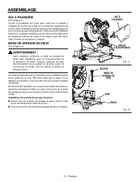
15 - English DUST BAG See Figure 11. A dust bag is provided for use on the miter saw. It fits over the exhaust port on the upper blade guard. To install it, squeeze the two metal clips to open the mouth of the bag and slide it on the exhaust port. Release the clips. The metal ring in the bag should ...
Page 16 - TO INSTALL/REPLACE THE BLADE; Do not
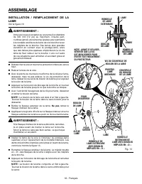
16 - English TO INSTALL/REPLACE THE BLADE See Figure 13. WARNING: A 12 in. blade is the maximum blade capacity of the saw. Never use a blade that is too thick to allow outer blade washer to engage with the flats on the spindle. Larger blades will come in contact with the blade guards, while thicker ...
Page 17 - LOCK; LOCKING/UNLOCKING THE SAW ARM; To unlock and raise the saw arm:
17 - English WARNING: Make sure the spindle lock button is not engaged before reconnecting saw into power source. Never engage spindle lock button when blade is rotating. CUTTING A SLOT IN THE ZERO CLEARANCE THROAT PLATE In order to use your compound miter saw, you must cut a slot through the zero c...
Page 18 - Never operate the saw without all guards securely; SQUARING THE BLADE TO THE FENCE
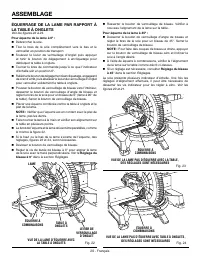
18 - English ASSEMBLY VIEW OF BLADE SQUARE WITH FENCE 10 15 20 25 22.5 31.6 30 35 40 45 50 15 20 25 30 35 40 45 31.6 22.5 50 Fig. 15 SLIDING MITER FENCE FENCE BLADE SQUARE MITER TABLE MITER LOCK LEVER 10 15 20 25 22.5 31.6 30 35 40 45 50 15 20 25 30 35 40 45 31.6 22.5 50 VIEW OF BLADE NOT SQUARE WIT...
Page 20 - SQUARING THE BLADE TO THE MITER TABLE; To square the blade at 0°:; To square the blade at 45°:
20 - English 10 15 20 25 22.5 31.6 30 35 40 45 50 15 20 25 30 35 40 45 31.6 22.5 50 10 15 20 25 22.5 31.6 30 35 40 45 50 15 20 25 30 35 40 45 31.6 22.5 50 ASSEMBLY VIEW OF BLADE NOT SQUARE WITH MITER TABLE, ADJUSTMENTS ARE REQUIRED 10 15 20 25 22.5 31.6 30 35 40 45 50 15 20 25 30 35 40 45 31.6 22.5 ...
Page 21 - APPLICATIONS; OPERATION
21 - English WARNING: Do not allow familiarity with tools to make you careless. Remember that a careless fraction of a second is sufficient to inflict severe injury. WARNING: Always wear eye protection with side shields marked to comply with ANSI Z87.1. Failure to do so could result in objects being...
Page 22 - LED LIGHTING SYSTEM
22 - English SHADOW OF BLADE TEETH PROJECTED ONTO WORKPIECE OPERATION LED LIGHTING SYSTEM See Figure 25. WARNING: Do not stare into the light beam (not even from a distance). Staring into the light beam may result in serious injury or vision loss. The LED lighting system casts the shadow of the blad...
Page 23 - BEVEL CUT; TO BEVEL CUT
23 - English WORK CLAMP Fig. 27 MITER CUT 10 15 20 25 22.5 31.6 30 35 40 45 50 15 20 25 30 35 40 45 31.6 22.5 50 Fig. 28 OPERATION BEVEL CUT WORK CLAMP Grasp the saw handle firmly. Depress the trigger lockout lever and squeeze the switch trigger. Allow several seconds for the blade to reach maximu...
Page 24 - TO COMPOUND MITER CUT
24 - English 15 20 25 22.5 31.6 30 35 40 45 50 15 20 25 30 35 40 45 31.6 22.5 50 10 10 0 Fig. 30 C-CLAMP OPERATION COMPOUND MITER CUT TO COMPOUND MITER CUT See Figure 30. A compound miter cut is a cut made using a miter angle and a bevel angle at the same time. This type of cut is used to make pictu...
Page 25 - TO SUPPORT LONG WORKPIECES; MUST
25 - English Fig. 31 OPERATION WORKPIECE SUPPORTS Slowly lower the blade into and through the workpiece. Release the switch trigger and allow the saw blade to stop rotating before raising the blade out of workpiece and removing the workpiece from the miter table. TO SUPPORT LONG WORKPIECES See F...
Page 26 - CUTTING COMPOUND MITERS; PITCH
26 - English CUTTING COMPOUND MITERS To aid in making the correct settings, the compound angle setting chart below has been provided. Since compound cuts are the most difficult to accurately obtain, trial cuts should be made in scrap material, and much thought and planning made, prior to making your...
Page 27 - CUTTING CROWN MOLDING; Bevel
27 - English When cutting crown molding by this method the bevel angle should be set at 33.9°. The bevel stop turret can be used to set the bevel angle to 33.9°. The miter angle should be set at 31.6° either right or left, depending on the desired cut for the application. See the chart below for cor...
Page 29 - RIGHT; CUTTING WARPED MATERIAL
29 - English OPERATION Fig. 38 RIGHT WRONG Fig. 37 CUTTING WARPED MATERIAL See Figures 37 - 38. When cutting warped material, always make sure it is positioned on the miter table with the convex side against the fence as shown in figure 37.If the warped material is positioned the wrong way as shown ...
Page 30 - ADJUSTMENTS; PIVOT ADJUSTMENTS; AUTHORIZED SERVICE CENTER.; TO ADJUST THE BEVEL PIVOT; AUTHORIZED SERVICE; 5° BEVEL ADJUSTMENT; BEVEL STOP
30 - English ADJUSTMENTS WARNING: Before performing any adjustment, make sure the tool is unplugged from the power supply. Failure to heed this warning could result in serious personal injury. The compound miter saw has been adjusted at the factory for making very accurate cuts. However, some of the...
Page 31 - ° BEVEL ADJUSTMENT
31 - English ADJUSTMENTS 0° BEVEL ADJUSTMENT See Figure 40. NOTE: These adjustments were made at the factory and normally do not require readjustment. Unplug the saw. Loosen the bevel lock knob by turning the knob counterclockwise. Square the blade to the miter table as described in the Assemb...
Page 32 - TO ADJUST THE MITER LOCK LEVER; NOTICE
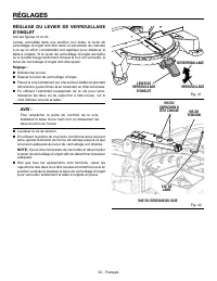
32 - English Fig. 41 Fig. 42 ADJUSTMENTS TO ADJUST THE MITER LOCK LEVER See Figures 41 and 42. When locked in an “unindexed” miter position, the miter lock lever should feel tight and secure, and considerable effort should be required to move the miter table. If the miter lock lever feels loose or t...
Page 33 - Proceed as follows when replacement is required:; MAINTENANCE; BRUSH CAP
33 - English WARNING: When servicing, use only identical replacement parts. Use of any other part can create a hazard or cause product damage. WARNING: Always wear eye protection with side shields marked to comply with ANSI Z87.1 during product operation. If operation is dusty, also wear a dust mask...
Page 34 - ACCESSORIES; CLEANING THE LED LENS; LED
34 - English ACCESSORIES Look for these accessories where you purchased this product or call 1-866-539-1710: AC9946 Miter Saw Utility Vehicle ....................................................................................................................... 994670001 Dust Bag Assembly .........
Page 35 - WARRANTY; RIDGID
35 - English WARRANTY Proof of purchase must be presented when requesting warranty service.Limited to RIDGID ® hand held and stationary power tools purchased 2/1/04 and after. This product is manufactured by TTI Consumer Power Tools, Inc. The trademark is licensed from RIDGID ® , Inc. All warranty c...
Page 36 - SÉCURITÉ DU LIEU DE TRAVAIL; Garder le lieu de travail propre et bien éclairé.; SÉCURITÉ ÉLECTRIQUE; RÈGLES DE SÉCURITÉ GÉNÉRALES; SÉCURITÉ PERSONNELLE
2 - Français AVERTISSEMENT : Li r e l es ave r t i s s e me nt s d e s écu r i té, l es instructions et les précisions et consulter les illustrations fournis avec cet outil électrique. Le fait de ne pas se conformer à l’ensemble des consignes présentées ci-dessous risque d’entraîner des décharges él...
Page 37 - Garder les outils bien affûtés et propres.; DÉPANNAGE; RÈGLES DE SÉCURITÉ DU SCIE À ONGLETS
3 - Français RÈGLES DE SÉCURITÉ GÉNÉRALES qui ne peut pas être contrôlé par son commutateur est dangereux et doit être réparé. Avant de procéder à un réglage, à un changement d’accessoire ou au rangement de l’outil, débranchez la prise de la source d’alimentation ou, si le bloc-piles est amovible,...
Page 38 - Couper une seule pièce à travailler à la fois.; Conserver ces instructions.; Utiliser un cordon prolongateur adéquat.
4 - Français de bois détachés ou les autres objets qui sont en contact avec la lame en rotation peuvent être projetés à haute vitesse. Couper une seule pièce à travailler à la fois. Les pièces à travailler empilées ne peuvent pas être suffisamment fixées au moyen d’une pince ou serrées et peuvent ...
Page 39 - RÈGLES DE SÉCURITÉ SUPPLÉMENTAIRES
5 - Français Veiller à bien connaître l’outil. Lire attentivement le manuel d’utilisation. Apprendre les applications et les limites de l’outil, ainsi que les risques spécifiques relatifs à son utilisation. Toujours porter une protection oculaire avec écrans latéraux certifiée conforme à la norm...
Page 40 - SYMBOLES
6 - Français SYMBOLES Certains des symboles ci-dessous peuvent être utilisés sur l’outil. Veiller à les étudier et à apprendre leur signification. Une interprétation correcte de ces symboles permettra d’utiliser l’outil plus efficacement et de réduire les risques. SYMBOLE NOM DÉSIGNATION / EXPLICATI...
Page 41 - CARACTÉRISTIQUES ÉLECTRIQUES; DOUBLE ISOLATION; CONNEXIONS ÉLECTRIQUES; une alimentation 120 V,; CORDONS PROLONGATEURS; Longueur
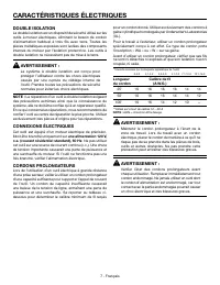
7 - Français CARACTÉRISTIQUES ÉLECTRIQUES DOUBLE ISOLATION La double isolation est un dispositif de sécurité utilisé sur les outils à moteur électriques, éliminant le besoin de cordon d’alimentation habituel à trois fils avec terre. Toutes les pièces métalliques exposées sont isolées des composants ...
Page 42 - GLOSSAIRE
8 - Français GLOSSAIRE Trou pilote (perceuses à colonne et scie à découper) Petit trou pratiqué dans une pièce servant de guide pour assurer la précision d’un trou de plus grand diamètre ou pour l’insertion d’une lame de scie à découper. Blocs poussoirs (pour dégauchisseuses/raboteuses) Dispositifs ...
Page 43 - CARACTÉRISTIQUES; FICHE TECHNIQUE
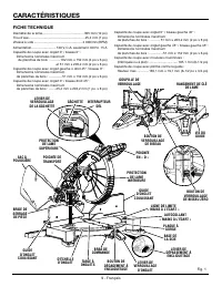
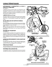
9 - Français CARACTÉRISTIQUES Fig. 1 FICHE TECHNIQUE Diamètre de la lame.............................................. 305 mm (12 po)Trou d’axe .............................................................. 25,4 mm (1 po)Vitesse à vide ..................................................... 4 000/min ...
Page 45 - LEVIER DE VERROUILLAGE D’ONGLET; BUTÉES POSITIVES DE LA TABLE À ONGLETS; BOUTON DE VERROUILLAGE DE BROCHE
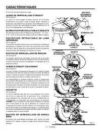
11 - Français CARACTÉRISTIQUES du trait de scie de la ligne de coupe. LEVIER DE VERROUILLAGE D’ONGLET Voir la figure 4. Le levier de verrouillage d’onglet permet de verrouiller solidement la scie selon l’angle d’onglet désiré. Abaisser le levier pour verrouiller la scie en place. Pour débloquer la s...
Page 47 - ASSEMBLAGE; DÉBALLAGE
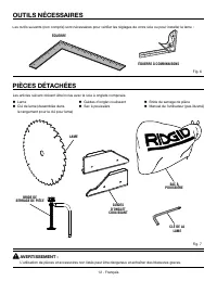
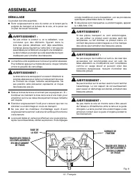
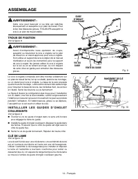
13 - Français ASSEMBLAGE DÉBALLAGE Ce produit doit être assemblé. Sortir soigneusement la scie du carton en la tenant par la poignée de transport et la base de la scie, et la poser sur un plan de travail horizontal. AVERTISSEMENT : Ne pas utiliser le produit si, en le déballant, vous constatez que...
Page 48 - TROUS DE FIXATION; CLÉ DE LAME
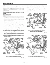
14 - Français AVERTISSEMENT : Cette scie peut basculer si sa tête est relâchée brusquement et assujettie à un plan de travail. Pour éviter des blessures graves, TOUJOURS assujettir la scie à un plan de travail stable. TROUS DE FIXATION Voir la figure 8. AVERTISSEMENT : Avant d’entreprendre toute opé...
Page 51 - POIGNÉE
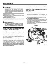
17 - Français ASSEMBLAGE ATTENTION : Toujours installer la lame avec les dents et la flèche imprimée sur son côté, orientées vers le bas à l’avant de la scie. Le sens de rotation de la lame est également représenté par une flèche estampée sur la protection supérieure. Serrer les boulons fermement....
Page 55 - UTILISATION
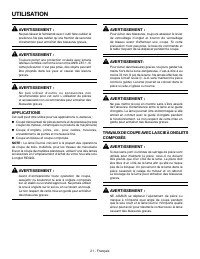
21 - Français AVERTISSEMENT : Ne pas laisser la familiarité avec l’outil faire oublier la prudence. Ne pas oublier qu’une fraction de seconde d’inattention peut entraîner des blessures graves. AVERTISSEMENT : Toujours porter une protection oculaire avec écrans latéraux certifiée conforme à la norme ...
Page 56 - SYSTÈME D’ÉCLAIRAGE DEL
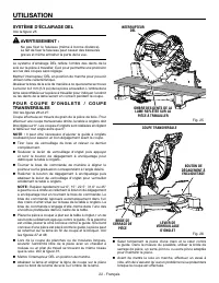
22 - Français UTILISATION SYSTÈME D’ÉCLAIRAGE DEL Voir la figure 25. AVERTISSEMENT : Ne pas fixer le faisceau (même à bonne distance). Le fait de fixer le faisceau peut causer des blessures graves et même entraîner la perte de la vue. Le système d’éclairage DEL reflète l’ombre des dents de la scie s...
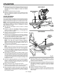
Page 57 - COUPE EN BISEAU
23 - Français COUPE D’ONGLET BRIDE DE SERRAGE DE PIÈCE Fig. 27 UTILISATION Saisir fermement le manche de la scie. Enfoncer le levier de verrouillage et appuyer sur la gâchette. Attendre quelques secondes que la lame atteigne sa vitesse de rotation maximale. Abaisser lentement la lame sur la pièc...
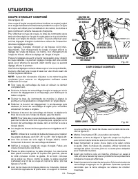
Page 58 - COUPE D’ONGLET COMPOSÉ
24 - Français UTILISATION COUPE D’ONGLET COMPOSÉ Voir la figure 30. Une coupe d’onglet composé revient à utiliser un angle d’onglet et un angle de biseau simultanément pendant la coupe. Ce type de coupe est utilisé pour la réalisation de cadres, de boîtes à pans inclinés et certains travaux de charp...
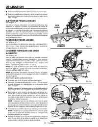
Page 59 - SUPPORT DE PIÈCES LONGUES
25 - Français UTILISATION Abaissez lentement la lame dans la pièce pour la couper. Relâcher la gâchette et attendre l’arrêt complet de la lame avant de la relever de la pièce et de retirer la pièce de la table à onglet. SUPPORT DE PIÈCES LONGUES Voir la figure 31. Les pièces longues nécessitent ...
Page 60 - COUPE D’ONGLETS COMPOSÉS; ANGLE DE
26 - Français UTILISATION COUPE D’ONGLETS COMPOSÉS Le tableau des réglages d’angles ci-dessous est conçu pour faciliter les réglages. Les coupes composées étant les plus difficiles à réaliser, des essais doivent être effectués sur des chutes et la coupe définitive ne doit être effectuée qu’après mûr...
Page 61 - COUPE DE MOULURE COURONNÉE
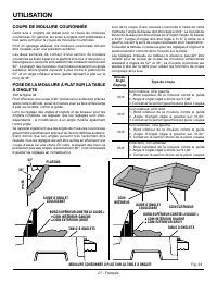
27 - Français UTILISATION COUPE DE MOULURE COURONNÉE Cette scie à onglets est idéale pour la coupe de moulures couronnées. En général, les scies à onglets sont préférables à tout autre outil pour la coupe de moulures couronnées.Pour un ajustage adéquat, les moulures couronnées doivent être coupées a...
Page 63 - COUPE DE PIÈCES VOILÉES; INCORRECT
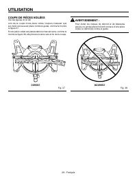
29 - Français UTILISATION COUPE DE PIÈCES VOILÉES Voir les figures 37 et 38. Lors de la coupe d’une pièce voilée, toujours s’assurer que son bord convexe est placé contre le guide, comme le montre la figure 37.Si une pièce voilée est placée dans le mauvais sens, comme le montre la figure 38, elle pi...
Page 64 - RÉGLAGES; RÉGLAGES DES PIVOTS; CENTRE DE SERVICE APRÈS-VENTE AGRÉÉ; RÉGLAGE DU PIVOT DE BISEAU; CENTRE; RÉGLAGE DU BISEAU À 45°; VIS DE RÉGLAGE
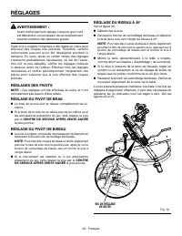
30 - Français RÉGLAGES AVERTISSEMENT : Avant d’effectuer tout réglage, s’assurer que l’outil est débranché. Le non respect de cet avertissement pourrait entraîner des blessures graves. Cette scie à onglets composés a été réglée en usine pour effectuer des coupes très précises. Toutefois, certains co...
Page 65 - RÉGLAGE DU BISEAU À 0°
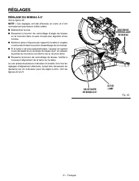
31 - Français RÉGLAGES RÉGLAGE DU BISEAU À 0° Voir la figure 40. NOTE : Ces réglages ont été effectués en usine et n’ont normalement pas besoin d’être refaits. Débrancher la scie. Desserrer le bouton de verrouillage d’angle de biseau en le tournant dans le sens inverse des aiguilles d’une montre...
Page 67 - ENTRETIEN; BOUCHON DE LA
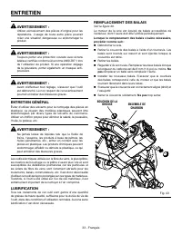
33 - Français AVERTISSEMENT : Utiliser exclusivement des pièces d’origine pour les réparations. L’usage de toute autre pièce pourrait créer une situation dangereuse ou endommager le produit. AVERTISSEMENT : Toujours porter une protection oculaire avec écrans latéraux certifiée conforme à la norme AN...
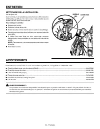
Page 68 - NETTOYAGE DE LA LENTILLE DEL; LENTILLE
34 - Français ACCESSOIRES Rechercher ces accessoires où vous avez acheté ce produit ou en appelant au 1-866-539-1710 : Chariot utilitaire pour scie à onglets AC9946 .............................................................................................................. 994670001 Ensemble d...
Page 69 - GARANTIE; RÉPARATIONS SOUS GARANTIE; AUTRES LIMITATIONS
35 - Français GARANTIE Une preuve d’achat doit être présentée pour toute demande de réparation sous garantie.Cette garantie se limite aux outils électriques à main et d’établi RIDGID ® achetés à partir du 1/2/04. Ce produit est fabriqué par TTI Consumer Power Tools, Inc., sous licence de marque de R...
Page 70 - ÁREA DE TRABAJO; SEGURIDAD ELÉCTRICA; REGLAS DE SEGURIDAD GENERALES; SEGURIDAD PERSONAL
2 - Español ADVERTENCIA: Lea todas las advertencias, instrucciones, ilustraciones y especificaciones proporcionadas con esta herramienta eléctrica. No seguir las instrucciones indicadas a continuación puede provocar descargas eléctricas, incendios o lesiones graves. Guarde todas las advertencias e i...
Page 71 - SERVICIO; REGLAS DE SEGURIDAD DE LA SIERRA INGLETEADORA
3 - Español REGLAS DE SEGURIDAD GENERALES No utilice la herramienta si el interruptor no enciende o no apaga. Cualquier herramienta eléctrica que no pueda controlarse con el interruptor es peligrosa y debe repararse. Desconecte el enchufe de la fuente de alimentación o retire el paquete de bater...
Page 73 - ADVERTENCIAS DE SEGURIDAD ADICIONALES
5 - Español F a m i l i a r í c e s e c o n s u h e r r a m i e n t a e l é c t r i c a . L e a cuidadosamente el manual del operador. Aprenda los usos, limitaciones y posibles peligros relacionados con esta herramienta. Siempre póngase protección ocular con protección lateral con la marca de cu...
Page 74 - SÍMBOLOS; SÍMBOLO
6 - Español SÍMBOLOS Es posible que se empleen en esta herramienta algunos de los siguientes símbolos. Le suplicamos estudiarlos y aprender su significado. Una correcta interpretación de estos símbolos le permitirá utilizar mejor y de manera más segura la herramienta. Alerta de seguridad Indica un p...
Page 75 - ASPECTOS ELÉCTRICOS; DOBLE AISLAMIENTO; CONEXIÓN ELÉCTRICA; CORDONES DE EXTENSIÓN; Longitud
7 - Español ASPECTOS ELÉCTRICOS DOBLE AISLAMIENTO El doble aislamiento es una característica de seguridad de las herramientas eléctricas, la cual elimina la necesidad de usar el típico cordón eléctrico de tres conductores con conexión a tierra. Todas las partes metálicas expuestas están aisladas de ...
Page 76 - GLOSARIO DE TÉRMINOS
8 - Español GLOSARIO DE TÉRMINOS Este es un corte en el cual la hoja no corta la pieza de trabajo en dos pedazos. Agujero guía (taladradoras de columna y sierras caladoras) Es un agujero pequeño taladrado en una pieza de trabajo, el cual sirve como guía para taladrar con precisión agujeros más grand...
Page 77 - CARACTERÍSTICAS
9 - Español CARACTERÍSTICAS Fig. 1 ESPECIFICACIONES DEL PRODUCTO Diámetro de la hoja .......................................... 305 mm (12 pulg.)Orificio del eje .................................................... 25,4 mm (1 pulg.)Velocidad en vacío ............................................ 4 00...
Page 79 - PALANCA DE SEGURIDAD DE INGLETE; BOTÓN TOPE PARA BISEL CERO
11 - Español CARACTERÍSTICAS PALANCA DE SEGURIDAD DE INGLETE Vea la figura 4. La palanca de seguridad de inglete asegura la sierra en el ángulo de inglete deseado. Apriete la palanca hacia abajo para asegurar la sierra en el lugar. Para soltar la sierra, levante la palanca de seguridad de inglete y ...
Page 81 - ARMADO; DESEMPAQUETADO
13 - Español Fig. 8 ARMADO DESEMPAQUETADO Este producto requiere armarse. Levante cuidadosamente de la caja la sierra sujetándola del mango de acarreo y de la base, y colóquela sobre una superficie de trabajo a nivel. ADVERTENCIA: No utilice este producto si alguna pieza incluida en la lista de pi...
Page 82 - AGUJEROS DE MONTAJE; LLAVE DE LA HOJA
14 - Español Fig. 9 ARMADO AGUJEROS DE MONTAJE Vea la figura 8. ADVERTENCIA: Antes de iniciar cualquier operación de corte, sujete con prensa(s) o atornille la sierra ingleteadora al banco de trabajo o pedestal para sierra ingleteadora aprobado. Si se utiliza un pedestal para sierra ingleteadora, le...
Page 83 - SACO CAPTAPOLVO
15 - Español ARMADO SACO CAPTAPOLVO ESCAPE DE SALIDA DE ASERRÍN Fig. 11 PRENSA DE TRABAJO Fig. 12 BASE AGUJERO PERILLA SACO CAPTAPOLVO Vea la figura 11. Se suministra un saco captapolvo para utilizarse con la sierra ingleteadora. Se acopla en la abertura de salida del aserrín, en la protección super...
Page 84 - PARA INSTALAR Y REEMPLACE LA HOJA
16 - Español PARA INSTALAR Y REEMPLACE LA HOJA Vea la figura 13. ADVERTENCIA: La sierra tiene capacidad para hojas hasta de un diámetro de 305 mm (12 pulg.). Nunca utilice una hoja tan gruesa que la arandela exterior de la hoja no se enganche en las partes planas del husillo. Las hojas más grandes t...
Page 85 - MANGO
17 - Español PROCEDIMIENTO DE TRABA Y DESTRABA EL BRAZO DE LA SIERRA Vea la figura 14. Para destrabar y levantar el brazo de la sierra: Sujete firmemente el mango en “D” y presione hacia abajo mientras tira de la pasador de seguridad hacia afuera, separándola de la carcasa de la sierra. Suelte l...
Page 87 - ESCUADRADO DE LA HOJA CON LA MESA DE
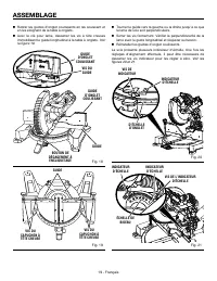
19 - Español ARMADO GUÍA TORNILLOS DE LA TAPA DE CABEZA HUECA TORNILLOS DE LA TAPA DE CABEZA HUECA Fig. 19 GUÍA GUÍA DE INGLETES DESLIZABLE Fig. 18 BOTÓN DE DETENCIÓN DE AFLOJE GUÍA DE INGLETES DESLIZABLE TORNILLO DE GUÍA Con la llave de la hoja, afloje los tornillos de cabeza hexagonal encargados...
Page 89 - FUNCIONAMIENTO
21 - Español ADVERTENCIA: Para evitar lesiones corporales serias, siempre presione la palanca de seguridad de bisel hacia abajo y perilla de fijación del bisel antes de efectuar un corte. De lo contrario podría producirse un movimiento del brazo de control o de la mesa de ingletes mientras se efectú...
Page 90 - SISTEMA DE ILUMINACIÓN LED
22 - Español FUNCIONAMIENTO SISTEMA DE ILUMINACIÓN LED Vea la figura 25. ADVERTENCIA: Evite mirar de frente el rayo de luz (aunque se encuentre lejos). Mirar de frente el rayo de luz puede causar lesiones graves o pérdida de la visión. El sistema de iluminación LED proyecta la sombra de la hoja en l...
Page 91 - PARA CORTAR A BISEL
23 - Español FUNCIONAMIENTO CORTE DE INGLETE PRENSA DE TRABAJO Fig. 27 transcurrir varios segundos para que la hoja alcance su velocidad máxima. Baje lentamente la hoja de la sierra haciendo que se introduzca y traspase la pieza de trabajo. Suelte el gatillo del interruptor y espere a que la hoj...
Page 92 - PARA CORTAR INGLETES COMPUESTOS
24 - Español FUNCIONAMIENTO CONTROL MANUAL DE BISEL PERILLA DE FIJACIÓN DEL BISEL PASADOR DE TOPE DE BISEL Fig. 29 BOTÓN TOPE PARA BISEL CERO 45º 33.9º 48º 33.9 45 48 o con una superficie de trabajo que esté al mismo nivel de la mesa de la sierra. Vea la figura 31. Encienda el interruptor LED. B...
Page 93 - APOYE LAS PIEZAS DE TRABAJO LARGAS
25 - Español FUNCIONAMIENTO Suelte el gatillo del interruptor y espere a que la hoja de la sierra deje de girar antes de levantarla de la pieza de trabajo y retirar la pieza de trabajo de la mesa de ingletes. APOYE LAS PIEZAS DE TRABAJO LARGAS Vea la figura 31. Las piezas de trabajo largas necesit...
Page 94 - CÓMO EFECTUAR CORTES A INGLETE COMBINADOS; AJUSTES DE ÁNGULOS COMBINADOS PARA ESTRUCTURAS COMUNES
26 - Español CÓMO EFECTUAR CORTES A INGLETE COMBINADOS Como ayuda para realizar los ajustes correctos, se suministra la siguiente tabla de ángulos combinados. Puesto que los cortes combinados son los más difíciles de obtener, deben efectuarse cortes de prueba en material de desecho, así como una gra...
Page 95 - CÓMO CORTAR MOLDURAS DE CORONA; Tipo de corte
27 - Español FUNCIONAMIENTO Al cortar molduras de corona con este método, el ángulo de bisel debe fijarse a 33,9°. Puede usarse el control manual de bisel para lograr un ángulo de bisel de 33,9°. El ángulo de inglete debe fijarse a 31,6°, a la derecha o izquierda, según el corte deseado para cada ap...
Page 96 - ENCAJE DE MOLDURA EN CORONA CONTRA
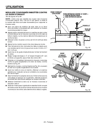
28 - Español FUNCIONAMIENTO CANTO INFERIOR CONTRA LA GUÍA = • LADO DER., ESQUINA INT. • LADO IZQ., ESQUINA EXT. ENCAJE DE MOLDURA EN CORONA CONTRA LA GUÍA DE INGLETE Vea las figuras 35 y 36. NOTA: Esta sierra puede cortar molduras en corona hasta 165,1 mm (6-1/2 pulg.) de altura. El tamaño y el núme...
Page 97 - CÓMO CORTAR MATERIAL TORCIDO; FORMA INCORRECTA
29 - Español FUNCIONAMIENTO CÓMO CORTAR MATERIAL TORCIDO Vea las figuras 37 y 38. Al cortar material torcido, asegúrese siempre de que esté situado sobre la mesa de ingletes con el canto convexo apoyado contra la guía, como se muestra en la figura 37.Si se coloca de forma incorrecta como se muestra ...
Page 98 - AJUSTE DEL PIVOTE DE BISEL; CENTRO DE SERVICIO AUTORIZADO; AJUSTE DE BISEL A 45°; TORNILLO DE AJUSTE; AJUSTES
30 - Español ADVERTENCIA: Antes de efectuar cualquier ajuste, asegúrese de que la herramienta esté desconectada del suministro de corriente. La inobservancia de esta advertencia podría causar lesiones corporales serias. La sierra ingleteadora combinada ha sido ajustada en la fábrica para producir co...
Page 99 - AJUSTE DE BISEL A 0°; TORNILLO; LLAVE DE
31 - Español AJUSTE DE BISEL A 0° Vea la figura 40. NOTA: Estos ajustes se realizaron en la fábrica y normalmente no requieren reajustarse. Desconecte la sierra. Afloje la perilla de fijación de bisel; para ello, gírela a la izquierda. Escuadre la hoja con respecto a la mesa de ingletes como s...
Page 100 - AJUSTE DE LA PALANCA DE FIJACIÓN DEL
32 - Español AJUSTES AJUSTE DE LA PALANCA DE FIJACIÓN DEL INGLETE Vea las figuras 41 y 42. En la posición de bloqueo no convencional del inglete, la palanca de seguridad de inglete debe estar firme y segura, y se requiere esfuerzo considerable para mover la mesa de ingletes. Si la palanca de segurid...
Page 101 - MANTENIMIENTO; MANTENIMIENTO GENERAL; Proceda como sigue cuando se requiera un reemplazo:
33 - Español MANTENIMIENTO ADVERTENCIA: Al dar servicio a la unidad, utilice sólo piezas de repuesto idénticas. El empleo de piezas diferentes puede presentar un peligro o causar daños al producto. ADVERTENCIA: Siempre póngase protección ocular con la marca de cumplimiento de la norma ANSI Z87.1. Si...
Page 102 - LIMPIEZA DE LA LENTE LED; Para limpiar la lente:; LENTE
34 - Español ACCESORIOS Busque estos accesorios donde adquirió este producto o llame al 1-866-539-1710: Carro de servicio para sierras ingleteadoras AC9946 ....................................................................................... 994670001 Conjunto del saco captapolvo ................
Page 103 - GARANTÍA
35 - Español GARANTÍA Debe presentarse prueba de la compra al solicitar servicio al amparo de la garantía.Se limita a las herramientas de mano y estacionarias RIDGID ® adquiridas a partir del 1 de febrero de 2004. Este producto está manufacturado por TTI Consumer Power Tools, Inc. La licencia de uso...
Page 104 - OPERATOR’S MANUAL; 2 in. DUAL BEVEL MITER SAW WITH LED; SCIE À ONGLETS À DOUBLE BISEAU DE 305 mm (12 po) AVEC DEL; Customer Service Information:; Información sobre servicio al consumidor:
995000640 11-21-22 (REV:03) OPERATOR’S MANUAL MANUEL D’UTILISATIONMANUAL DEL OPERADOR 12 in. DUAL BEVEL MITER SAW WITH LED SCIE À ONGLETS À DOUBLE BISEAU DE 305 mm (12 po) AVEC DEL SIERRA INGLETEADORA DE BISEL DOBLE DE 305 mm (12 pulg.) CON LED R4123 TTI CONSUMER POWER TOOLS, INC. P.O. Box 1427Ander...


 Ridgid 122XL Manual
 Ridgid 258 Manual
 Ridgid 300 Manual
 Ridgid 600 Manual
 Ridgid 690 Manual
 Ridgid 700 Manual
 Ridgid 902 Manual
 Ridgid 1210 Manual
 Ridgid 1233 Manual
 Ridgid 2032-OS Manual
 Ridgid AC9940 Manual
 Ridgid AC9944 Manual
 Ridgid AC99401 Manual