Page 3 - Safety Information
3 Contents Safety Information Safety Information ∙ The components included in this package are prone to damage from electrostatic discharge (ESD). Please adhere to the following instructions to ensure successful computer assembly. ∙ Ensure that all components are securely connected. Loose connection...
Page 4 - Specifications
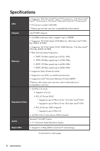
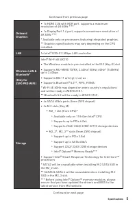
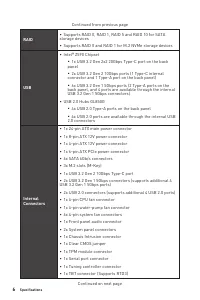
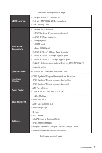
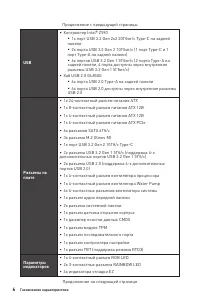
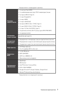
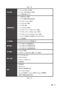
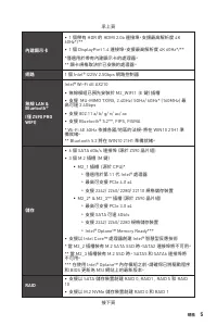
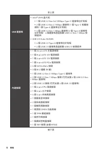
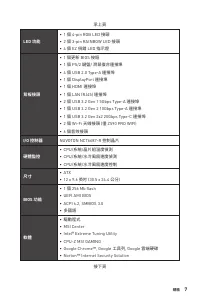
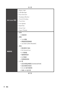
4 Specifications Specifications CPU ∙ Supports 10th Gen Intel® Core™ Processors, 11th Gen Intel® Core™ Processors, Pentium® Gold and Celeron® Processors* ∙ Processor socket LGA1200 * Please go to intel.com for compatibility information Chipset Intel® Z590 chipset Memory ∙ 4x DDR4 memory slots, suppo...
Page 10 - LAN Port LED Status Table
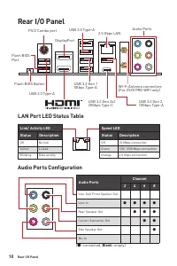
10 Rear I/O Panel Rear I/O Panel Link/ Activity LEDStatus Description Off No link Yellow Linked Blinking Data activity Speed LEDStatus Description Off 10 Mbps connection Green 100/ 1000 Mbps connection Orange 2.5 Gbps connection LAN Port LED Status Table USB 3.2 Gen 1 5Gbps Type-A Flash BIOS Button ...
Page 11 - Overview of Components
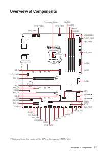
11 Rear I/O Panel Overview of Components Overview of Components * Distance from the center of the CPU to the nearest DIMM slot. SATA6 SATA5 SYS_FAN5 SYS_FAN4 JCOM1 JTBT1 JFP2 JTPM1 JRGB1 SATA▼1▲2 SATA▼3▲4 JCI1 M2_3 M2_2 M2_1 SYS_FAN1 JUSB4 JUSB5 JUSB3 JUSB1 JUSB2 PCIE_PWR1 SYS_FAN3 SYS_FAN2 CPU_FAN1...
Page 12 - CPU Socket; Important
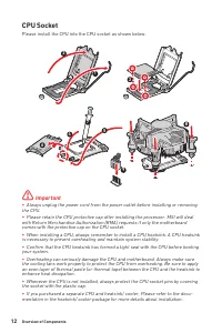
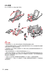
12 Overview of Components CPU Socket Please install the CPU into the CPU socket as shown below. ⚠ Important ∙ Always unplug the power cord from the power outlet before installing or removing the CPU. ∙ Please retain the CPU protective cap after installing the processor. MSI will deal with Return Mer...
Page 13 - Memory module installation recommendation
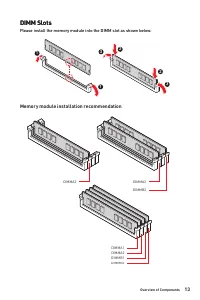
13 Overview of Components Overview of Components DIMM Slots Please install the memory module into the DIMM slot as shown below. DIMMB2 DIMMA2 DIMMA2 DIMM Slots Please install the memory module into the DIMM slot as shown below. 1 1 2 3 3 2 Memory module installation recommendation DIMMB2 DIMMB1 DIMM...
Page 15 - JAUD1: Front Audio Connector
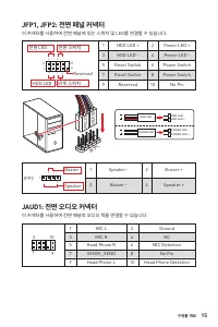
15 Overview of Components Overview of Components JFP1, JFP2: Front Panel Connectors These connectors connect to the switches and LEDs on the front panel. 1 2 10 9 + + + - - - - + Power LED HDD LED Reset Switch Reserved Power Switch 1 HDD LED + 2 Power LED + 3 HDD LED - 4 Power LED - 5 Reset Switch 6...
Page 20 - JTPM1: TPM Module Connector
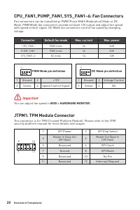
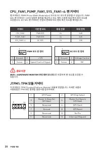
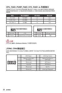
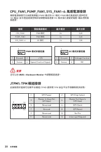
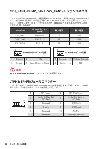
20 Overview of Components 1 2 12 11 1 SPI Power 2 SPI Chip Select 3 Master In Slave Out (SPI Data) 4 Master Out Slave In (SPI Data) 5 Reserved 6 SPI Clock 7 Ground 8 SPI Reset 9 Reserved 10 No Pin 11 Reserved 12 Interrupt Request JTPM1: TPM Module Connector This connector is for TPM (Trusted Platfor...
Page 21 - JCI1: Chassis Intrusion Connector; Using chassis intrusion detector; JCOM1: Serial Port Connector
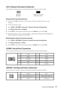
21 Overview of Components Overview of Components JCI1: Chassis Intrusion Connector This connector allows you to connect the chassis intrusion switch cable. Normal (default) Trigger the chassis intrusion event Using chassis intrusion detector 1. Connect the JCI1 connector to the chassis intrusion swi...
Page 22 - Resetting BIOS to default values; JRAINBOW1~2: Addressable RGB LED connectors; CAUTION
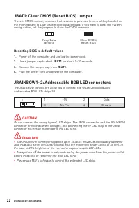
22 Overview of Components JBAT1: Clear CMOS (Reset BIOS) Jumper There is CMOS memory onboard that is external powered from a battery located on the motherboard to save system configuration data. If you want to clear the system configuration, set the jumpers to clear the CMOS memory. Keep Data (defau...
Page 23 - EZ Debug LED; JRGB1: RGB LED connector
23 Overview of Components Overview of Components EZ Debug LED These LEDs indicate the status of the motherboard. CPU - indicates CPU is not detected or fail. DRAM - indicates DRAM is not detected or fail. VGA - indicates GPU is not detected or fail. BOOT - indicates booting device is not detected or...
Page 24 - Installing Windows® 10; Installing Drivers; MSI Center User Guide
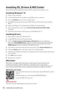
24 Installing OS, Drivers & MSI Center Installing OS, Drivers & MSI Center Please download and update the latest utilities and drivers at www.msi.com Installing Windows® 10 1. Power on the computer. 2. Insert the Windows® 10 installation disc/USB into your computer. 3. Press the Restart butt...
Page 25 - UEFI BIOS
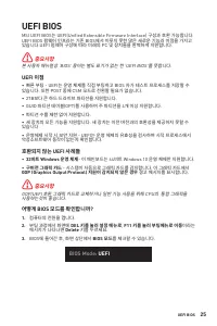
25 Installing OS, Drivers & MSI Center UEFI BIOS UEFI BIOS MSI UEFI BIOS is compatible with UEFI (Unified Extensible Firmware Interface) architecture. UEFI has many new functions and advantages that traditional BIOS cannot achieve, and it will completely replace BIOS in the future. The MSI UEFI ...
Page 26 - BIOS Setup; Entering BIOS Setup; Function key; BIOS User Guide
26 UEFI BIOS BIOS Setup The default settings offer the optimal performance for system stability in normal conditions. You should always keep the default settings to avoid possible system damage or failure booting unless you are familiar with BIOS. ⚠ Important ∙ BIOS items are continuously update for...
Page 27 - Resetting BIOS; Updating BIOS; Updating BIOS with M-FLASH
27 UEFI BIOS UEFI BIOS Resetting BIOS You might need to restore the default BIOS setting to solve certain problems. There are several ways to reset BIOS: ∙ Go to BIOS and press F6 to load optimized defaults. ∙ Short the Clear CMOS jumper on the motherboard. ∙ Press the Clear CMOS button on the rear ...
Page 28 - Updating the BIOS with MSI Center
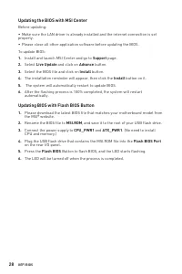
28 UEFI BIOS Updating the BIOS with MSI Center Before updating: ∙ Make sure the LAN driver is already installed and the internet connection is set properly. ∙ Please close all other application software before updating the BIOS. To update BIOS: 1. Install and launch MSI Center and go to Support page...
Page 29 - 목차; MSI®
1 <變數 1> 목차 목차 안전 지침 .......................................................................................................... 3 사양 ................................................................................................................... 4 후면 I/O 패널 ....................................
Page 31 - 안전 지침
3 목차 안전 지침 안전 지침 ∙ 이 패키지에 포함된 부품은 정전기 방전(ESD)에 의해 파손될 우려가 있으므로 다음의 설명에 따라 컴퓨터를 조립하십시오. ∙ 모든 부품이 제대로 연결되었는지 확인하십시오. 제대로 연결되지 않을 경우, 컴퓨터가 부품을 인식하지 못하거나 컴퓨터를 켤 수가 없게 됩니다. ∙ 부품의 예리한 부분에 손을 다칠 수 있으므로 메인보드 취급시 가장자리 부분을 잡으십시오. ∙ 메인보드를 취급할 때 정전기로 인한 피해를 방지하기 위해 정전기 방전 ESD 손목 스트랩을 착용할 것을 권장합니다. ESD 손목 스트랩이 없...
Page 32 - 사양
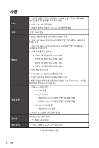
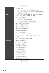
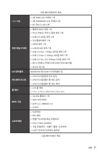
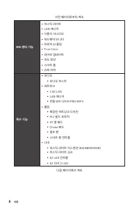
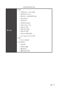
4 사양 사양 CPU ∙ 10세대 인텔® 코어™ 프로세서, 11세대 인텔® 코어™ 프로세서, 펜티엄 골드 및 셀레론® 프로세서 지원* ∙ 소켓 LGA1200 프로세서 * 더 많은 호환성 정보는 intel.com을 방문하세요. 칩셋 인텔 ® Z590 칩셋 메모리 ∙ DDR4 메모리 슬롯 4개, 최대 128GB* 지원 ∙ 1R 2133/ 2666/ 2933 MHz(10세대 인텔® CPU용)(by JEDEC & POR) 지원 ∙ 1R 2133/ 2666/ 2933/ 3200 MHz (11세대 인텔® CPU용)(by JEDEC &a...
Page 39 - 구성품 개요
11 후면 I/O 패널 구성품 개요 구성품 개요 * CPU 중앙에서 가장 가까운 DIMM 슬롯까지의 거리입니다. SATA6 SATA5 SYS_FAN5 SYS_FAN4 JCOM1 JTBT1 JFP2 JTPM1 JRGB1 SATA▼1▲2 SATA▼3▲4 JCI1 M2_3 M2_2 M2_1 SYS_FAN1 JUSB4 JUSB5 JUSB3 JUSB1 JUSB2 PCIE_PWR1 SYS_FAN3 SYS_FAN2 CPU_FAN1 SYS_FAN6 PUMP_FAN1 PCI_E1 PCI_E2 PCI_E3 JBAT1 PCI_E4 JDASH1 프로세서...
Page 40 - CPU 소켓; 중요사항
12 구성품 개요 CPU 소켓 아래와 같이 CPU 소켓에 CPU를 설치해주세요. ⚠ 중요사항 ∙ CPU를 설치하거나 제거하기 전에 전원 코드를 콘센트에서 뽑아주시기 바랍니다. ∙ 프로세서를 설치한 후, CPU 보호 캡을 보관하시기 바랍니다. 반품시 메인보드와 CPU 소켓 보호 캡이 함께 제공되어야만 MSI에서 반품(RMA) 요청 처리를 진행할 수 있습니다. ∙ CPU 설치시, CPU 히트싱크를 반드시 설치하세요. CPU 히트싱크는 과열을 방지하고 시스 템 성능을 유지하는데 꼭 필요합니다. ∙ 시스템을 부팅하기 전에 CPU 히트싱크가...
Page 41 - DIMM 슬롯
13 구성품 개요 구성품 개요 DIMM 슬롯 아래 그림과 같이 메모리 모듈을 DIMM 슬롯에 설치하여 주십시오. DIMMB2 DIMMA2 DIMMA2 메모리 모듈 설치 (추천) DIMMB2 DIMMB1 DIMMA2 DIMMA1 1 1 2 3 3 2
Page 47 - JTBT1: 썬더볼트 추가 카드 커넥터
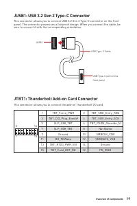
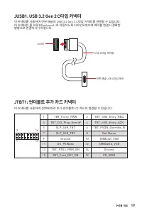
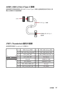
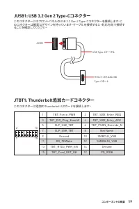
19 구성품 개요 구성품 개요 JUSB1: USB 3.2 Gen 2 C타입 커넥터 이 커넥터를 사용하여 전면 패널의 USB 3.2 Gen 2 C타입 커넥터를 연결할 수 있습니다. 이 커넥터는 풀 프루프(foolproof )로 작동하도록 디자인되었으며 케이블 연결시 정확한 방향으로 연결하시기 바랍니다. JUSB1 USB C타입 케이블 전면 패널 USB C타입 포트 JTBT1: 썬더볼트 추가 카드 커넥터 이 커넥터를 사용하여 선택에 따라 추가 썬더볼트 I/O 카드와 연결할 수 있습니다. 1 2 16 15 1 TBT_Force_PWR 2...
Page 49 - 섀시 침입 탐지기 사용하기; 섀시 침입 알람 재설정하기
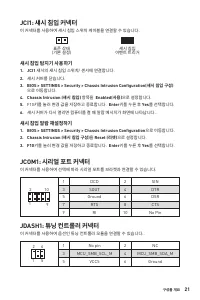
21 구성품 개요 구성품 개요 JCI1: 섀시 침입 커넥터 이 커넥터를 사용하여 섀시 침입 스위치 케이블을 연결할 수 있습니다. 표준 상태 (기본 설정) 섀시 침입 이벤트 트리거 섀시 침입 탐지기 사용하기 1. JCI1 섀시의 섀시 침입 스위치/ 센서에 연결합니다. 2. 섀시 커버를 닫습니다. 3. BIOS > SETTINGS > Security > Chassis Intrusion Configuration(섀시 침입 구성) 으로 이동합니다. 4. Chassis Intrusion (섀시 침입) 항목을 Enabled(사...
Page 50 - 기본 값으로 BIOS 리셋하기
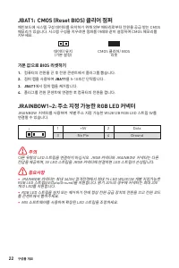
22 구성품 개요 JBAT1: CMOS (Reset BIOS) 클리어 점퍼 메인보드에 시스템 구성 데이터를 유지하기 위해 외부 배터리로부터 전원을 공급 받는 CMOS 메모리가 있습니다. 시스템 구성을 지우려면 점퍼를 아래와 같이 설정하여 CMOS 메모리를 지우세요. 데이터 유지 (기본 설정) CMOS 클리어/ BIOS 리셋 기본 값으로 BIOS 리셋하기 1. 컴퓨터의 전원을 끈 후 전원 콘센트에서 플러그를 뽑습니다. 2. 점퍼 캡을 사용하여 JBAT1 을 5-10초간 단락합니다. 3. JBAT1 에서 점퍼 캡을 제거합니다. 4. 플...
Page 51 - EZ 디버그 LED
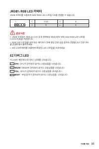
23 구성품 개요 구성품 개요 EZ 디버그 LED 이 LED는 메인보드의 디버그 상태를 나타냅니다. JRGB1: RGB LED 커넥터 JRGB 커넥터를 사용하여 5050 RGB LED 스트립 12V을 연결할 수 있습니다. ⚠ 중요사항 ∙ JRGB 커넥터는 최대 3A (12V) 정격 전력에서 최대 2미터 연속 5050 RGB LED 스트립 (12V/G/R/B)을 지원합니다. ∙ RGB LED 스트립을 설치 또는 제거하기 전에 항상 전원 공급 장치의 전원을 끄고 전원 코드 를 콘센트에서 뽑아주세요. ∙ MSI 소프트웨어를 사용하여 확장...
Page 52 - 드라이버 설치하기; MSI 센터; MSI 센터 사용자 가이드
24 OS, 드라이버 & 유틸리티 설치하기 OS, 드라이버 & 유틸리티 설치하기 공식 웹사이트 www.msi.com 을 방문하여 최신 버전의 유틸리티와 드라이버를 다운로드 및 업데이트하세요 . Windows ® 10 설치하기 1. 컴퓨터의 전원을 켭니다. 2. Windows® 10 설치 디스크/USB를 컴퓨터에 삽입합니다. 3. 컴퓨터 케이스의 Restart 버튼을 누릅니다. 4. 컴퓨터가 POST (Power-On Self Test)하는 동안 F11 키를 눌러 부팅 메뉴로 이동합니다. 5. 부팅 메뉴에서 Window...
Page 54 - 기능 키; BIOS 사용자 가이드
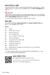
26 UEFI BIOS BIOS (바이오스) 설정 기본 설정은 일반적인 조건에서 시스템의 안정성을 위해 최적의 성능을 제공합니다. BIOS에 익숙하지 않을 경우, 시스템 손상 또는 부팅 실패를 방지하기 위해 항상 기본 설정을 유지 하기 바랍니다. ⚠ 중요사항 ∙ BIOS 항목은 시스템 성능 향상을 위해 지속적으로 업데이트됩니다. 따라서 여기에 제공된 설명은 최신 BIOS와 조금 상이할 수 있으므로 참조용으로만 사용하십시오. 또한 BIOS 항목에 대해서는 HELP(도움말) 의 설명을 참고할 수 있습니다. ∙ BIOS 화면, 옵션 및 ...
Page 55 - BIOS 리셋
27 UEFI BIOS UEFI BIOS BIOS 리셋 문제 해결을 위해 BIOS 기본 설정을 복원해야할 경우가 나타날 수 있습니다. BIOS를 리셋하는 방법에는 다음과 같은 몇가지가 있습니다. ∙ BIOS로 이동한 후 F6 를 눌러 최적화된 기본 값을 로드합니다. ∙ 메인보드의 CMOS 클리어 점퍼를 단락시킵니다. ∙ 후면 I/O 패널의 CMOS 클리어 버튼을 누릅니다. ⚠ 중요사항 CMOS 데이터를 삭제하기 전에 컴퓨터 전원이 꺼져 있는지 확인해야 합니다. BIOS를 재설정하려면 CMOS 클리어 점퍼/ 버튼 섹션을 참조하세요. ...
Page 56 - MSI 센터로 BIOS 업데이트
28 UEFI BIOS MSI 센터로 BIOS 업데이트 업데이트 하기 전: ∙ LAN 드라이버가 이미 설치되어 있고 인터넷이 제대로 연결되었는지 확인하세요. ∙ BIOS 업데이트 하기 전, 모든 다른 응용 프로그램을 끄십시오. BIOS 업데이트: 1. MSI 센터를 설치 및 시작하고 Support 페이지로 이동합니다. 2. Live Update 를 선택하고 Advance 버튼을 클릭합니다. 3. BIOS 파일을 선택하고 Install 버튼을 클릭합니다. 4. 설치 알림이 나타나면 Install 버튼을 누릅니다. 5. BIOS를 업데...
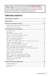
Page 57 - Table des matières; Merci d’avoir acheté la carte mère MSI®
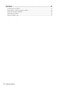
1 <變數 1> Table des matières Table des matières Informations de sécurité ................................................................................. 3 Spécifications ................................................................................................... 4 Panneau arrière Entré...
Page 59 - Informations de sécurité
3 Table des matières Informations de sécurité Informations de sécurité ∙ Les composants dans l’emballage peuvent être endommagés par des décharges électrostatiques (ESD). Pour vous assurer de correctement monter votre ordinateur, veuillez vous référer aux instructions ci-dessous. ∙ Assurez-vous de b...
Page 60 - Spécifications
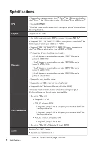
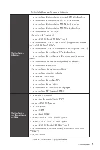
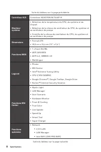
4 Spécifications Spécifications CPU ∙ Support des processeurs Intel® Core™ de 10ème génération, Intel® Core™ de 11ème génération, Pentium® Gold et Celeron® ∙ Socket LGA1200 * Veuillez vous au site www.intel.com pour plus d’informations de compatibilité. Chipset Chipset Intel® Z590 Mémoire ∙ 4 x slot...
Page 66 - Panneau arrière Entrée / Sortie; Tableau explicatif de l’état de la LED du port LAN
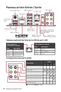
10 Panneau arrière Entrée / Sortie Panneau arrière Entrée / Sortie LED indiquant la connexion et l’activité Etat Description Eteint Pas de connexion Jaune Connexion correcte Clignote Activité en cours LED indiquant la vitesse Etat Description Eteint 10 Mb/s Vert 100 / 1000 Mb/s Orange 2,5 Gb/s Table...
Page 67 - Vue d’ensemble des composants
11 Panneau arrière Entrée / Sortie Vue d’ensemble des composants Vue d’ensemble des composants * Distance entre le centre du CPU et le slot DIMM le plus proche. SATA6 SATA5 SYS_FAN5 SYS_FAN4 JCOM1 JTBT1 JFP2 JTPM1 JRGB1 SATA▼1▲2 SATA▼3▲4 JCI1 M2_3 M2_2 M2_1 SYS_FAN1 JUSB4 JUSB5 JUSB3 JUSB1 JUSB2 PCI...
Page 68 - Socket Processeur
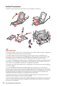
12 Vue d’ensemble des composants Socket Processeur Installer le processeur dans le socket comme indiqué ci-dessous. ⚠ Important ∙ Avant d’installer ou de retirer le processeur du socket, veillez à toujours débranch- er le câble d’alimentation de la prise électrique. ∙ Veuillez garder le capot de pro...
Page 69 - Slots DIMM; Installation recommandée de module mémoire
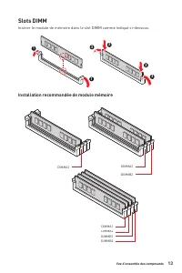
13 Vue d’ensemble des composants Vue d’ensemble des composants Slots DIMM Insérer le module de mémoire dans le slot DIMM comme indiqué ci-dessous. DIMMB2 DIMMA2 DIMMA2 Installation recommandée de module mémoire DIMMB2 DIMMB1 DIMMA2 DIMMA1 1 1 2 3 3 2
Page 71 - JFP1, JFP2 : Connecteurs de panneau avant; JAUD1 : Connecteur audio avant
15 Vue d’ensemble des composants Vue d’ensemble des composants JFP1, JFP2 : Connecteurs de panneau avant Ces connecteurs se lient aux interrupteurs et indicateurs LED du panneau avant. 1 2 10 9 + + + - - - - + Power LED HDD LED Reset Switch Reserved Power Switch 1 HDD LED + 2 Power LED + 3 HDD LED -...
Page 73 - d’alimentation
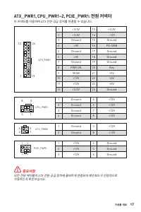
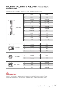
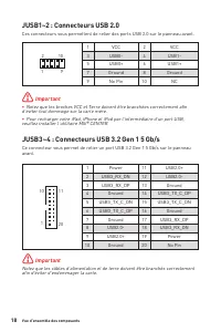
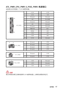
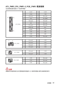
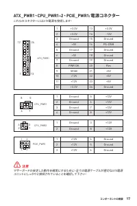
17 Vue d’ensemble des composants Vue d’ensemble des composants ATX_PWR1, CPU_PWR1~2, PCIE_PWR1 : Connecteurs d’alimentation Ces connecteurs vous permettent de relier une alimentation ATX. ⚠ Important Veuillez vous assurer que tous les câbles d’alimentation sont branchés aux connecteurs adéquats afin...
Page 75 - JTBT1 : Connecteur de carte additionnelle Thunderbolt
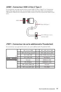
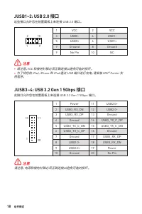
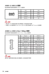
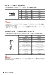
19 Vue d’ensemble des composants Vue d’ensemble des composants JUSB1 : Connecteur USB 3.2 Gen 2 Type-C Ce connecteur vous permet de relier un port USB 3.2 Gen 2 Type-C sur le panneau avant. Pour plus de sécurité, ce connecteur a été conçu pour offrir une excellente robustesse. Quand vous connectez l...
Page 76 - JTPM1 : Connecteur de module TPM
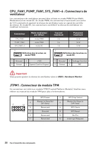
20 Vue d’ensemble des composants JTPM1 : Connecteur de module TPM Ce connecteur est relié à un module TPM (Trusted Platform Module). Veuillez vous référer au manuel du module TPM pour plus d’informations. CPU_FAN1, PUMP_FAN1, SYS_FAN1~6 : Connecteurs de ventilateur Les connecteurs de ventilateur peu...
Page 77 - JCI1 : Connecteur intrusion châssis; Réinitialisation de l’alerte intrusion châssis; JCOM1 : Connecteur de port série
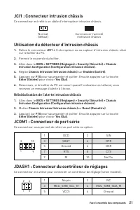
21 Vue d’ensemble des composants Vue d’ensemble des composants JCI1 : Connecteur intrusion châssis Ce connecteur est relié à un câble d’interrupteur intrusion châssis. Normal (défaut) Commencer l’activité instrusion châssis Utilisation du détecteur d’intrusion châssis 1. Reliez le connecteur JCI1 à ...
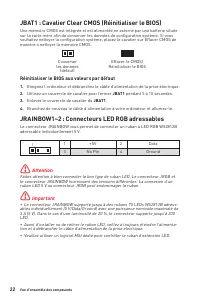
Page 78 - Réinitialiser le BIOS aux valeurs par défaut; JRAINBOW1~2 : Connecteurs LED RGB adressables; Attention
22 Vue d’ensemble des composants JBAT1 : Cavalier Clear CMOS (Réinitialiser le BIOS) Une mémoire CMOS est intégrée et est alimentée en externe par une batterie située sur la carte mère afin de conserver les données de configuration système. Si vous souhaitez nettoyer la configuration système, placez...
Page 79 - Installer OS, Pilotes et MSI Center; Installer Windows® 10
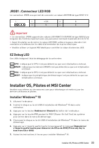
23 Vue d’ensemble des composants Installer OS, Pilotes et MSI Center EZ Debug LED Ces LEDs indiquent l’état de débogage de la carte mère. JRGB1 : Connecteur LED RGB Le connecteur JRGB vous permet de connecter un ruban LED RGB de type 5050 12 V. ⚠ Important ∙ Le connecteur JRGB supporte des rubans LE...
Page 80 - Installer les pilotes; Guide d’utilisation de MSI Center
24 Installer OS, Pilotes et MSI Center Installer les pilotes 1. Allumez l’ordinateur sous Windows® 10. 2. Insérez MSI® Drive Disc dans le lecteur optique. 3. Cliquez sur la fenêtre popup Choisir quoi faire avec ce disque (Select to choose what happens with this disc) , puis choisissez Lancer DVDSetu...
Page 82 - Configuration du BIOS; Entrer dans l’interface Setup du BIOS; Touches de fonction; Guide d’utilisation du BIOS
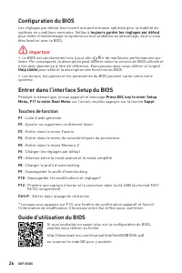
26 UEFI BIOS Configuration du BIOS Les réglages par défaut fournissent une performance optimale pour la stabilité du système en conditions normales. Veillez à toujours garder les réglages par défaut pour éviter d’endommager le système ou tout problème au démarrage, sauf si vous êtes familier avec le...
Page 83 - Réinitialiser le BIOS; Mettre le BIOS à jour; Mettre le BIOS à jour avec M-FLASH
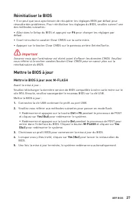
27 UEFI BIOS UEFI BIOS Réinitialiser le BIOS ∙ Il se peut que vous ayez besoin de récupérer les réglages BIOS par défaut pour résoudre des problèmes. Pour réinitialiser les réglages du BIOS, veuillez suivre l’une des méthodes suivantes : ∙ Allez dans le Setup du BIOS et appuyez sur F6 pour charger l...
Page 84 - Mettre le BIOS à jour avec MSI Center
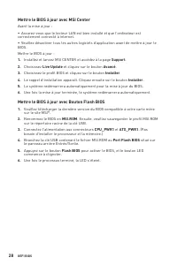
28 UEFI BIOS Mettre le BIOS à jour avec MSI Center Avant la mise à jour : ∙ Assurez-vous que le lecteur LAN est bien installé et que l’ordinateur est correctement connecté à internet. ∙ Veuillez désactiver tous les autres logiciels d’application avant de mettre à jour le BIOS.Mettre le BIOS à jour :...
Page 85 - Inhalt; Danke, dass Sie sich für das MSI®; PRO; Motherboard entschieden haben. Dieses Handbuch
1 <變數 1> Inhalt Inhalt Sicherheitshinweis .......................................................................................... 3 Spezifikationen ................................................................................................ 4 Rückseite E/A .................................
Page 87 - Sicherheitshinweis
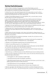
3 Inhalt Sicherheitshinweis Sicherheitshinweis ∙ Die im Paket enthaltene Komponenten sind der Beschädigung durch elektrostatischen Entladung (ESD). Beachten Sie bitte die folgenden Hinweise, um die erfolgreichen Computermontage sicherzustellen. ∙ Stellen Sie sicher, dass alle Komponenten fest angesc...
Page 88 - Spezifikationen
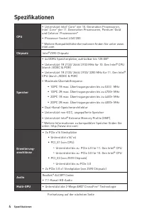
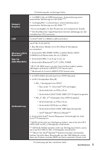
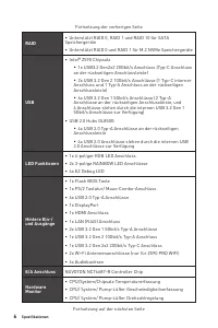
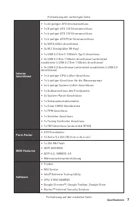
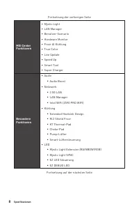
4 Spezifikationen Spezifikationen CPU ∙ Unterstützt Intel ® Core ™ der 10. Generation Prozessoren, Intel ® Core ™ der 11. Generation Prozessoren, Pentium ® Gold und Celeron ® Prozessoren* ∙ Prozessor Sockel LGA1200 * Weitere Kompatibilitätsinformationen finden Sie unter www. intel.com Chipsatz Intel...
Page 95 - Übersicht der Komponenten
11 Rückseite E/A Übersicht der Komponenten Übersicht der Komponenten * Abstand zwischen der Mitte der CPU und dem nächsten DIMM-Steckplatz. SATA6 SATA5 SYS_FAN5 SYS_FAN4 JCOM1 JTBT1 JFP2 JTPM1 JRGB1 SATA▼1▲2 SATA▼3▲4 JCI1 M2_3 M2_2 M2_1 SYS_FAN1 JUSB4 JUSB5 JUSB3 JUSB1 JUSB2 PCIE_PWR1 SYS_FAN3 SYS_F...
Page 96 - CPU Sockel; Wichtig
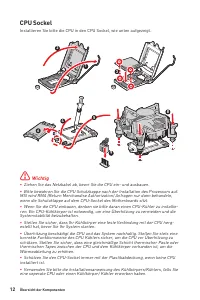
12 Übersicht der Komponenten CPU Sockel Installieren Sie bitte die CPU in den CPU Sockel, wie unten aufgezeigt. ⚠ Wichtig ∙ Ziehen Sie das Netzkabel ab, bevor Sie die CPU ein- und ausbauen. ∙ Bitte bewahren Sie die CPU Schutzkappe nach der Installation des Prozessors auf. MSI wird RMA (Return Mercha...
Page 97 - Speichermodul-Installationsempfehlung
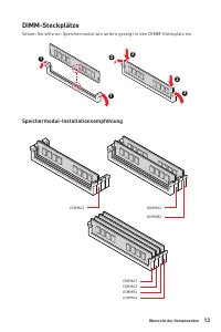
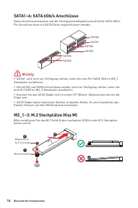
13 Übersicht der Komponenten Übersicht der Komponenten DIMMB2 DIMMA2 DIMMA2 DIMM-Steckplätze Setzen Sie bitte ein Speichermodul wie untern gezeigt in den DIMM-Steckplatz ein. Speichermodul-Installationsempfehlung DIMMB2 DIMMB1 DIMMA2 DIMMA1 1 1 2 3 3 2
Page 99 - JAUD1: Audioanschluss des Frontpanels
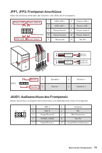
15 Übersicht der Komponenten Übersicht der Komponenten JFP1, JFP2: Frontpanel-Anschlüsse Diese Anschlüsse verbinden die Schalter und LEDs des Frontpanels. 1 2 10 9 + + + - - - - + Power LED HDD LED Reset Switch Reserved Power Switch 1 HDD LED + 2 Power LED + 3 HDD LED - 4 Power LED - 5 Reset Switch ...
Page 103 - JTBT1: Anschluss für Thunderbolt-Erweiterungskarte
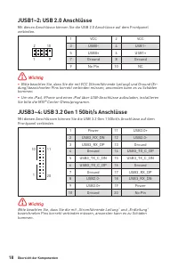
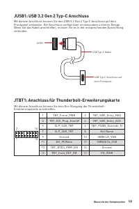
19 Übersicht der Komponenten Übersicht der Komponenten JUSB1: USB 3.2 Gen 2 Typ-C Anschluss Mit diesem Anschluss können Sie den USB 3.2 Gen 2 Typ-C Anschluss auf dem Frontpanel verbinden. Der Anschluss verfügt über ein besonders sicheres Design. Wenn Sie das Kabel anschließen, müssen Sie es in der e...
Page 104 - Stromanschlüsse für Lüfter
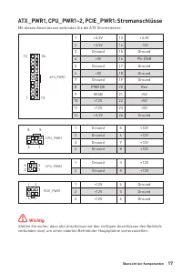
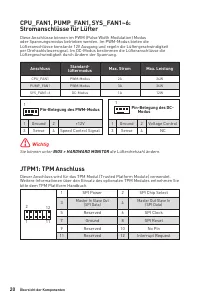
20 Übersicht der Komponenten JTPM1: TPM Anschluss Dieser Anschluss wird für das TPM Modul (Trusted Platform Module) verwendet. Weitere Informationen über den Einsatz des optionalen TPM Modules entnehmen Sie bitte dem TPM Plattform Handbuch. CPU_FAN1, PUMP_FAN1, SYS_FAN1~6: Stromanschlüsse für Lüfter...
Page 105 - JCI1: Gehäusekontaktanschluss; Gehäusekontakt-Detektor verwenden; Gehäusekontakt-Warnung zurücksetzen; JCOM1: Serieller Anschluss
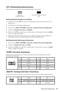
21 Übersicht der Komponenten Übersicht der Komponenten JCI1: Gehäusekontaktanschluss Dieser Anschluss wird mit einem Kontaktschalter verbunden. Normal (Standardwert) Löse den Gehäuseeingriff aus Gehäusekontakt-Detektor verwenden 1. Schließen Sie den JCI1 -Anschluss am Gehäusekontakt-Schalter/ Sensor...
Page 106 - Rücksetzen des BIOS auf Standardwerte; JRAINBOW1~2: Adressierbare RGB LED Anschlüsse; ACHTUNG
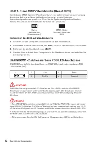
22 Übersicht der Komponenten JBAT1: Clear CMOS Steckbrücke (Reset BIOS) Der Onboard CMOS Speicher (RAM) wird durch eine externe Spannungsversorgung durch eine Batterie auf dem Motherboard versorgt, um die Daten der Systemkonfiguration zu speichern. Wenn Sie die Systemkonfiguration löschen wollen, mü...
Page 107 - JRGB1: RGB LED Anschluss
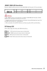
23 Übersicht der Komponenten Übersicht der Komponenten EZ Debug LED Diese LEDs zeigen den Status des Motherboards an. CPU - - CPU wird nicht erkannt oder ist fehlerhaft. DRAM - DRAM wird nicht erkannt oder ist fehlerhaft. VGA - GPU wird nicht erkannt oder ist fehlerhaft. BOOT - Boot-Gerät wird nicht...
Page 108 - Installation von OS, Treibern & MSI Center; Installation von Windows® 10; MSI Center Benutzerhandbuch
24 Installation von OS, Treibern & MSI Center Installation von OS, Treibern & MSI Center Laden Sie die neuesten Treiber und Dienstprogramme von www.msi.com herunter und aktualisieren Sie sie Installation von Windows® 10 1. Schalten Sie den Computer ein. 2. Legen Sie die Windows® 10 Disk oder...
Page 109 - UEFI
25 Installation von OS, Treibern & MSI Center UEFI BIOS UEFI BIOS Das MSI UEFI-BIOS ist mit der UEFI-Architektur (Unified Extensible Firmware Interface) kompatibel. UEFI hat viele neue Funktionen und besitzt Vorteile, die das traditionelle BIOS nicht bieten kann. UEFI wird das BIOS in Zukunft vo...
Page 110 - Öffnen des BIOS Setups; Funktionstasten; BIOS-Benutzerhandbuch
26 UEFI BIOS BIOS Setup Die Standardeinstellungen bieten die optimale Leistung für die Systemstabilität unter Normalbedingungen. Sie sollten immer die Standardeinstellungen behalten , um mögliche Schäden des Systems oder Boot-Fehler zu vermeiden, außer Sie besitzen ausreichende BIOS Kenntnisse. ⚠ Wi...
Page 111 - Reset des BIOS; Aktualisierung des BIOS; Aktualisierung des BIOS mit dem M-FLASH-Programm
27 UEFI BIOS UEFI BIOS Reset des BIOS Sie können die Werkseinstellung wieder herstellen, um bestimmte Probleme zu lösen. Es gibt verschiedene Möglichkeiten, um das BIOS zurückzusetzen: ∙ Öffnen Sie das BIOS und drücken Sie F6 , um optimierten Einstellungen zu laden. ∙ Schließen Sie die Clear CMOS St...
Page 112 - Aktualisierung des BIOS mit MSI DRAGON CENTER; Wählen Sie; licken Sie auf das; Aktualisierung des BIOS mit Flash BIOS Taste
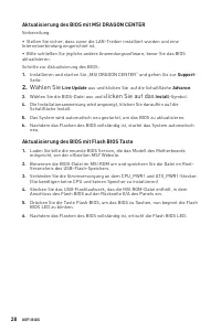
28 UEFI BIOS Aktualisierung des BIOS mit MSI DRAGON CENTER Vorbereitung: ∙ Stellen Sie sicher, dass zuvor die LAN-Treiber installiert wurden und eine Internetverbindung eingerichtet ist. ∙ Bitte schließen Sie jegliche andere Anwendungssoftware, bevor Sie das BIOS aktualisieren.Schritte zur Aktualisi...
Page 113 - Содержание; Благодарим Вас за покупку материнской платы MSI®
1 <變數 1> Содержание Содержание Безопасное использование продукции ....................................................... 3 Технические характеристики ....................................................................... 4 Задняя панель портов ввода/ вывода .....................................
Page 115 - Безопасное использование продукции
3 Содержание Безопасное использование продукции Безопасное использование продукции ∙ Компоненты, входящие в комплект поставки могут быть повреждены статическим электричеством. Для успешной сборки компьютера, пожалуйста, следуйте указаниям ниже. ∙ Убедитесь, что все компоненты компьютера подключены д...
Page 116 - Технические характеристики
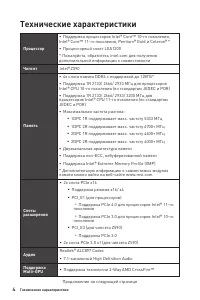
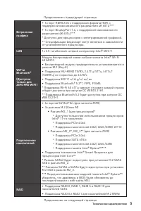
4 Технические характеристики Технические характеристики Процессор ∙ Поддержка процессоров Intel® Core™ 10-го поколения, Intel® Core™ 11-го поколения, Pentium® Gold и Celeron® * ∙ Процессорный сокет LGA1200 * Пожалуйста, обратитесь intel.com для получения дополнительной информации о совместимости Чип...
Page 122 - Задняя панель портов ввода/ вывода; Таблица состояний индикатора порта LAN; Конфигурация портов Аудио
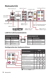
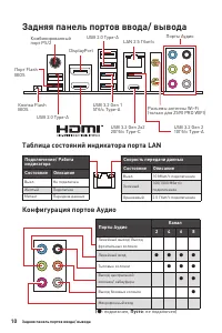
10 Задняя панель портов ввода/ вывода Задняя панель портов ввода/ вывода Подключение/ Работа индикатораСостояние Описание Выкл. Не подключен Желтый Подключен Мигает Передача данных Скорость передачи данныхСостояние Описание Выкл. 10 Мбит/с подключение Зеленый 100/1000 Мбит/с подключение Оранжевый 2....
Page 123 - Компоненты материнской платы
11 Задняя панель портов ввода/ вывода Компоненты материнской платы Компоненты материнской платы * Расстояние от центра процессора до ближайшего слота DIMM. SATA6 SATA5 SYS_FAN5 SYS_FAN4 JCOM1 JTBT1 JFP2 JTPM1 JRGB1 SATA▼1▲2 SATA▼3▲4 JCI1 M2_3 M2_2 M2_1 SYS_FAN1 JUSB4 JUSB5 JUSB3 JUSB1 JUSB2 PCIE_PWR...
Page 125 - Слоты DIMM; Рекомендации по установке модулей памяти
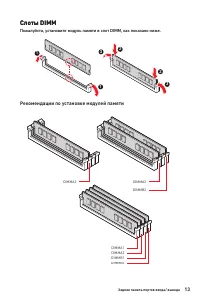
13 Задняя панель портов ввода/ вывода Задняя панель портов ввода/ вывода Слоты DIMM Пожалуйста, установите модуль памяти в слот DIMM, как показано ниже. DIMMB2 DIMMA2 DIMMA2 Слоты DIMM Пожалуйста, установите модуль памяти в слот DIMM, как показано ниже. Рекомендации по установке модулей памяти DIMMB...
Page 127 - JAUD1: Разъем аудио передней панели
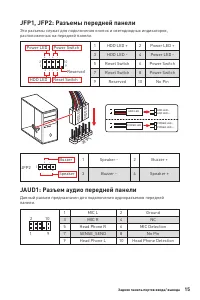
15 Задняя панель портов ввода/ вывода Задняя панель портов ввода/ вывода JFP1, JFP2: Разъемы передней панели Эти разъемы служат для подключения кнопок и светодиодных индикаторов, расположенных на передней панели. 1 2 10 9 + + + - - - - + Power LED HDD LED Reset Switch Reserved Power Switch 1 HDD LED...
Page 129 - питания
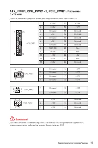
17 Задняя панель портов ввода/ вывода Задняя панель портов ввода/ вывода ATX_PWR1, CPU_PWR1~2, PCIE_PWR1: Разъемы питания Данные разъемы предназначены для подключения блока питания ATX. ⚠ Внимание! Для обеспечения стабильной работы системной платы проверьте надежность подключения всех кабелей питани...
Page 131 - JTBT1: Разъем для установки карты расширения
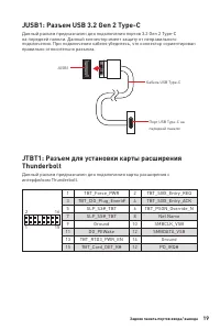
19 Задняя панель портов ввода/ вывода Задняя панель портов ввода/ вывода JUSB1: Разъем USB 3.2 Gen 2 Type-C Данный разъем предназначен для подключения портов 3.2 Gen 2 Type-C на передней панели. Данный коннектор имеет защиту от неправильного подключения. При подключении кабеля убедитесь, что коннект...
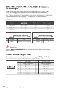
Page 132 - JTPM1: Разъем модуля ТРМ
20 Задняя панель портов ввода/ вывода 1 2 12 11 1 SPI Power 2 SPI Chip Select 3 Master In Slave Out (SPI Data) 4 Master Out Slave In (SPI Data) 5 Reserved 6 SPI Clock 7 Ground 8 SPI Reset 9 Reserved 10 No Pin 11 Reserved 12 Interrupt Request JTPM1: Разъем модуля ТРМ Данный разъем используется для по...
Page 133 - JCI1: Разъем датчика открытия корпуса; Использование датчика открытия корпуса; JCOM1: Разъем последовательного порта
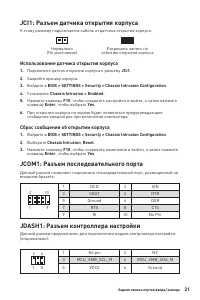
21 Задняя панель портов ввода/ вывода Задняя панель портов ввода/ вывода JCI1: Разъем датчика открытия корпуса К этому разъему подключается кабель от датчика открытия корпуса. Нормально (По умолчанию) Разрешить запись по событию открытия корпуса Использование датчика открытия корпуса 1. Подключите д...
Page 134 - Сброс настроек BIOS до значений по умолчанию
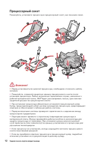
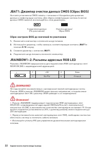
22 Задняя панель портов ввода/ вывода JBAT1: Джампер очистки данных CMOS (Сброс BIOS) На плате установлена CMOS память с питанием от батарейки для хранения данных о конфигурации системы. Для сброса конфигурации системы (очистки данных CMOS памяти), воспользуйтесь этим джампером. Сохранение данных (П...
Page 135 - Индикаторы отладки EZ; JRGB1: Разъем RGB LED
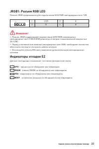
23 Задняя панель портов ввода/ вывода Задняя панель портов ввода/ вывода Индикаторы отладки EZ Данные светодиоды показывают состояния материнской платы. CPU - процессор не обнаружен или поврежден. DRAM - память DRAM не обнаружена или повреждена. VGA - видеокарта не обнаружена или повреждена. BOOT - ...
Page 136 - Установка ОС, драйверов и MSI Center; Установка Windows® 10; Установка драйверов; Инструкции по использованию MSI Center
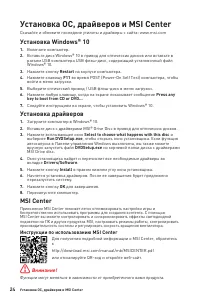
24 Установка ОС, драйверов и MSI Center Установка ОС, драйверов и MSI Center Скачайте и обновите последние утилиты и драйверы с сайта: www.msi.com Установка Windows® 10 1. Включите компьютер. 2. Вставьте диск Windows® 10 в привод для оптических дисков или вставьте в разъем USB компьютера USB флэш-ди...
Page 137 - Преимущества UEFI
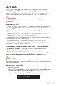
25 Установка ОС, драйверов и MSI Center UEFI BIOS UEFI BIOS MSI UEFI BIOS совместим с архитектурой UEFI (Unified Extensible Firmware Interface). Прошивка UEFI имеет множество новых функций и преимуществ, которые не поддерживаются традиционным BIOS. UEFI полностью заменит традиционный BIOS в будущем....
Page 138 - Вход в настройки BIOS; Функциональные клавиши; Инструкции по настройке BIOS
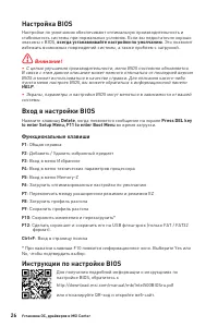
26 Установка ОС, драйверов и MSI Center Настройка BIOS Настройки по умолчанию обеспечивают оптимальную производительность и стабильность системы при нормальных условиях. Если вы недостаточно хорошо знакомы с BIOS, всегда устанавливайте настройки по умолчанию . Это позволит избежать возможных поврежд...
Page 139 - Сброс BIOS; Обновление BIOS при помощи M-FLASH
27 Установка ОС, драйверов и MSI Center Установка ОС, драйверов и MSI Center Сброс BIOS В некоторых ситуациях необходимо выполнить восстановление настроек BIOS до значений по умолчанию. Существует несколько способов сброса настроек: ∙ Войдите в BIOS и нажмите клавишу F6 для загрузки оптимизированных...
Page 140 - Обновление BIOS при помощи MSI Center
28 Установка ОС, драйверов и MSI Center Обновление BIOS при помощи MSI Center Перед обновлением: ∙ Убедитесь, что драйвер локальной сети установлен и есть подключение к сети Интернет. ∙ Перед обновлением BIOS закройте все остальные приложения. Обновление BIOS: 1. Установите и запустите MSI Center, и...
Page 141 - 目录; 感谢您购买了 MSI®
1 <變數 1> 目录 目录 安全信息........................................................................................................... 3 规格 .................................................................................................................. 4 后置 I/O 面板 ......................................
Page 143 - 安全信息
3 目录 安全信息 安全信息 ∙ 此包装中包含的的组件有可能到静电放电 (ESD) 损坏。请遵守以下注意事项,以确保 成功组装计算机。 ∙ 确保所有组件连接牢固。若连接不紧可能会导致计算机无法识别组件或无法开启。 ∙ 拿起主板时请手持主板边缘,避免触及主板的敏感组件。 ∙ 当拿取主板时,建议佩戴静电放电 (ESD) 腕带,以防止静电损坏其配置。如果 ESD 腕带 无法使用,请在拿取主板前通过接触其它金属物体释放自身的静电。 ∙ 在不安装主板时,请将主板放在静电屏蔽容器或防静电垫上。 ∙ 在打开计算机前,确保计算机机箱内的主板或任何位置上没有松动的螺丝或金属组 件。 ∙ 在安装完成之前不要启动计...
Page 144 - 规格
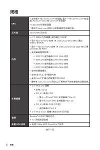
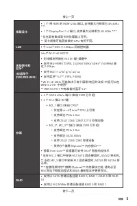
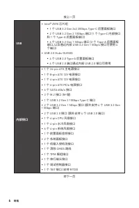
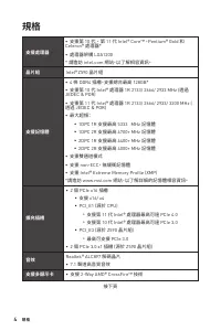
4 规格 规格 CPU ∙ 支持第十代 Intel® Core™ 处理器,第十一代 Intel® Core™ 处理 器,Pentium® Gold 和 Celeron® 处理器 * ∙ LGA1200 针脚处理器 * 请访问 intel.com 网站,以获取兼容性详细信息。 芯片组 Intel® Z590 芯片组 内存 ∙ 4 个 DDR4 内存插槽,支持高达 128GB* ∙ 第十代 Intel® CPU 支持 1R 2133/ 2666/ 2933 MHz (通过 JEDEC 和 POR) ∙ 第十一代 Intel® CPU 支持 1R 2133/ 2666/ 2933/ 3200 MHz...
Page 150 - LAN 端口 LED 状态表; 音频端口配置
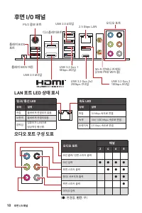
10 后置 I/O 面板 后置 I/O 面板 连线/ 工作灯号状态 描述 关 网络未连接 黄色 网络已连接 闪烁 网络数据在使用中 速度灯号状态 描述 关 传输速率 10 Mbps 绿色 传输速率 100/ 1000 Mbps 橙色 传输速率 2.5 Gbps LAN 端口 LED 状态表 USB 3.2 Gen 1 5Gbps Type-A 更新 BIOS 按钮 PS/2 组合端口 2.5 Gbps LAN DisplayPort端口 USB 2.0 Type-A USB 2.0 Type-A 音频端口 Wi-Fi 天线接口 (仅适用于 Z590 PRO WIFI ) USB 3.2 Gen...
Page 151 - 组件概述
11 后置 I/O 面板 组件概述 组件概述 * CPU 中心位置到最近的 DIMM 插槽的距离。 SATA6 SATA5 SYS_FAN5 SYS_FAN4 JCOM1 JTBT1 JFP2 JTPM1 JRGB1 SATA▼1▲2 SATA▼3▲4 JCI1 M2_3 M2_2 M2_1 SYS_FAN1 JUSB4 JUSB5 JUSB3 JUSB1 JUSB2 PCIE_PWR1 SYS_FAN3 SYS_FAN2 CPU_FAN1 SYS_FAN6 PUMP_FAN1 PCI_E1 PCI_E2 PCI_E3 JBAT1 PCI_E4 JDASH1 处理器底座 CPU_PWR1 CP...
Page 152 - CPU 底座; 注意
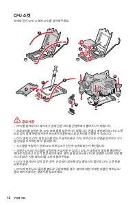
12 组件概述 CPU 底座 将 CPU 安装至 CPU 底座,请如下图示。 ⚠ 注意 ∙ 安装或移除 CPU 之前,请先关闭电源,并将电源线由插座上拔除。 ∙ 安装完处理器后请保留 CPU 保护盖。微星将要求授权的 (RMA) 在处理退货验证需要 主板上附带 CPU 底座上的保护盖。 ∙ 当您安装 CPU 时,请确认已安装好 CPU 风扇。对防止过热和维持系统的稳定性 CPU 风扇是非常必要的。 ∙ 确认在系统启动前 CPU 风扇已经牢固的粘贴在 CPU 上。 ∙ 温度过高会严重损害 CPU 和系统,请务必确认所使用的降温风扇始终能够正常工作, 保护 CPU 以免过热烧毁。确认,您已在 CP...
Page 153 - DIMM 插槽; 内存模块安装建议
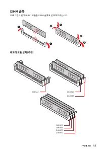
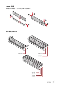
13 组件概述 组件概述 DIMM 插槽 将安装内存模块插入至 DIMM 插槽,请如下图示。 DIMMB2 DIMMA2 DIMMA2 内存模块安装建议 DIMMB2 DIMMB1 DIMMA2 DIMMA1 1 1 2 3 3 2
Page 159 - JTBT1: Thunderbolt 附加卡接口
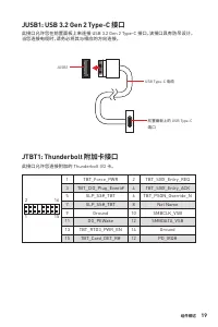
19 组件概述 组件概述 JUSB1: USB 3.2 Gen 2 Type-C 接口 此接口允许您在前置面板上来连接 USB 3.2 Gen 2 Type-C 接口。该接口具有防呆设计。 当您连接电缆时,请务必将其与相应的方向连接。 JUSB1 USB Type-C 电缆 前置面板上的 USB Type-C 端口 JTBT1: Thunderbolt 附加卡接口 此接口允许您连接附加的 Thunderbolt I/O 卡。 1 2 16 15 1 TBT_Force_PWR 2 TBT_S0IX_Entry_REQ 3 TBT_CIO_Plug_Event# 4 TBT_S0IX_Entry...
Page 161 - 使用机箱入侵检测器
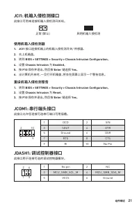
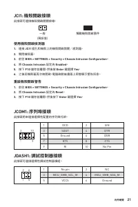
21 组件概述 组件概述 JCI1: 机箱入侵检测接口 此接口可用来连接机箱入侵检测开关线。 正常 (默认) 启用机箱入侵检测 使用机箱入侵检测器 1. JCI1 接口连接机箱上的机箱入侵检测开关/ 传感器。 2. 合上机箱盖。 3. 转到 BIOS > SETTINGS > Security > Chassis Intrusion Configuration 。 4. 设置 Chassis Intrusion 为 Enabled 。 5. 按 F10 保存并退出,然后按 Enter 键选择 Yes 。 6. 当计算机开启时,一旦打开机箱盖,将会在屏幕上显示一个警告信息。 重...
Page 162 - 重启 BIOS 为默认值
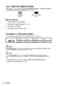
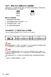
22 组件概述 JBAT1: 清除 CMOS (重启 BIOS) 跳线 主板上建有一个 CMOS 内存,其中保存的系统配置数据需要通过一枚外置的电池来维持 它。如果您想清除系统配置,设置跳线清除 CMOS 内存。 保留数据 (默认) 清除 CMOS/ 重启 BIOS 重启 BIOS 为默认值 1. 关闭计算机电源,并拔下电源插头。 2. 使用跳线帽让 JBAT1 短路持续约 5-10 秒。 3. 移除 JBAT1 上的跳线帽。 4. 插上电源插头并开启计算机上电源。 JRAINBOW1~2: 寻址 RGB LED 接口 JRAINBOW 接口允许您连接 WS2812B 单独寻址 RGB LED...
Page 163 - 简易侦错 LED 灯
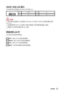
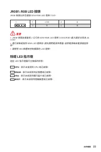
23 组件概述 组件概述 简易侦错 LED 灯 LED 指示灯在主板中的状态。 CPU - 表示 CPU 无法检测或故障。 DRAM - 表示 DRAM 无法检测或故障。 VGA - 表示 GPU 无法检测或故障。 BOOT - 表示启动设备无法检测或故障。 JRGB1: RGB LED 接口 JRGB 接口允许您连接 5050 RGB LED 灯条 12V。 ⚠ 注意 ∙ JRGB 接口支持高达 2 米连续的 5050 RGB LED 灯条 (12V/G/R/B) 和最大额定功率 3A (12V)。 ∙ 在安装或拆卸 RGB LED 灯条时,请先关闭电源,并将电源线由插座上拔除。 ∙ 请使用...
Page 164 - 安装操作系统,驱动程序和 MSI Center; 安装 Windows® 10; 安装驱动; MSI Center 用户指南
24 安装操作系统,驱动程序和 MSI Center 安装操作系统,驱动程序和 MSI Center 请通过 www.msi.com下载并更新最新的工具程序和驱动程序 安装 Windows® 10 1. 启动计算机电源。 2. 将 Windows® 10 安装光盘/ USB 插入计算机。 3. 按下计算机上的 Restart 按钮。 4. 计算机 POST (开机自我测试) 过程中按 F11 键进入启动菜单。 5. 从引导菜单中选择 Windows® 10 安装光盘/USB。 6. 当屏幕显示 Press any key to boot from CD or DVD... 信息时按住任意键。 ...
Page 166 - 进入 BIOS 设置; 功能键; BIOS 用户指南
26 UEFI BIOS BIOS 设置 在正常情况下,默认设置为系统稳定提供最佳性能。您应该 始终保持默认设置 ,以避免可 能出现的系统损坏或无法开机,除非您熟悉 BIOS 设置。 ⚠ 注意 ∙ 为了获得更好的系统性能,BIOS 项目描述不断更新。因此,这些描述可能有些稍微的 不同,仅供参考。您也可以参考 BIOS 项目描述的 帮助 信息面板。 ∙ BIOS 屏幕,选项和设置会因您的系统而有差异。 进入 BIOS 设置 在开机程序中,当屏幕上出现 Press DEL key to enter Setup Menu, F11 to enter Boot Menu 信息,按下 Delete 键。...
Page 167 - 重启 BIOS; 更新 BIOS
27 UEFI BIOS UEFI BIOS 重启 BIOS 您可能需要还原默认的 BIOS 设置来解决某些问题。有几种方法来重启 BIOS: ∙ 转到 BIOS,然后按 F6 载入优化设置默认值。 ∙ 短路主板上的清除 CMOS 跳线。 ∙ 按后置 I/O 面板上的清除 CMOS 按钮。 ⚠ 注意 在清除 CMOS 数据之前,请确保计算机已关机。请参考清除 CMOS 跳线/ 按钮部分,以了 解重启 BIOS 的相关信息。 更新 BIOS 使用 M-FLASH 更新 BIOS 更新前:请从 MSI 的网站下载符合您主板型号的最新 BIOS 文件。 然后将 BIOS 文件保存到 U 盘中。更新 ...
Page 168 - 使用 MSI Center 更新 BIOS
28 UEFI BIOS 使用 MSI Center 更新 BIOS 更新前: ∙ 请确认已安装 LAN 驱动程序以及正确设置因特网连接。 ∙ 在更新 BIOS 之前,请关闭所有其他应用程序软件。 更新 BIOS: 1. 安装并运行 MSI Center,然后转到 Support 页面。 2. 选择 Live Update ,然后单击 Advanced 按钮。 3. 选择 BIOS 文件,然后单击 Install 按钮。 4. 安装提示将出现,然后单击其上的 Install 按钮。 5. 系统将自动重启以更新 BIOS。 6. BIOS 刷新 100% 完成后,系统将自动重启。 使用更新 BI...
Page 169 - 目錄; 感謝您購買 MSI®
1 <變數 1> 目錄 目錄 安全說明........................................................................................................... 3 規格 .................................................................................................................. 4 背板 I/O .........................................
Page 171 - 安全說明
3 目錄 安全說明 安全說明 ∙ 本包裝內所含的組件可能因靜電 (ESD) 受到損壞。請務必依循以下指示,以確保能成 功組裝電腦。 ∙ 請確定所有組件均確實連接妥善。如有鬆脫,可能會造成電腦無法識別該組件或無法 啟動電腦。 ∙ 拿取主機板時,請抓主機板的邊緣,以免碰觸到較易損壞的組件。 ∙ 拿取主機板時,建議您戴靜電手環,以免產生靜電損壞主機板。若無靜電手環,請先觸 摸其他金屬物品以讓自身放電,再碰觸主機板。 ∙ 若未安裝主機板,請務必將其存放於靜電屏蔽的容器中或置於防靜電桌墊上。 ∙ 開機之前,請先確認主機板上方或機殼內,無任何鬆脫的螺絲或其他金屬組件。 ∙ 安裝完成再開機,以免損壞組件或傷...
Page 172 - 規格
4 規格 規格 支援處理器 ∙ 支援第 10 代 、 第 11 代 Intel® Core™ ,Pentium® Gold 和 Celeron® 處理器* ∙ 處理器架構 LGA1200 * 請造訪 intel.com 網站,以了解相容資訊。 晶片組 Intel® Z590 晶片組 支援記憶體 ∙ 4 條 DDR4 插槽,支援總合最高 128GB* ∙ 支援第 10 代 Intel® 處理器 1R 2133/ 2666/ 2933 MHz (透過 JEDEC & POR) ∙ 支援第 11 代 Intel® 處理器 1R 2133/ 2666/ 2933/ 3200 MHz ( 透過 ...
Page 178 - 網路連接埠 LED 燈狀態表; 音效連接埠設置
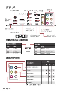
10 背板 I/O 背板 I/O 連線/ 工作燈號狀態 說明 關閉 未連線 黃燈 已連線 閃爍 資料傳輸中 速度燈號狀態 說明 關閉 傳輸速率 10 Mbps 綠燈 傳輸速率 100/ 1000 Mbps 橘燈 傳輸速率 2.5 Gbps 網路連接埠 LED 燈狀態表 USB 3.2 Gen 1 5Gbps Type-A 更新 BIOS 按鈕 PS/2 復合連接埠 2.5 Gbps 網路連 接埠 DisplayPort USB 2.0 Type-A USB 2.0 Type-A 音效接頭 Wi-Fi 天線接頭 (僅 Z590 PRO WIFI) USB 3.2 Gen 2x2 20Gbps T...
Page 179 - 元件總覽
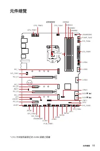
11 背板 I/O 元件總覽 元件總覽 * CPU 中央點到最靠近的 DIMM 插槽之距離 SATA6 SATA5 SYS_FAN5 SYS_FAN4 JCOM1 JTBT1 JFP2 JTPM1 JRGB1 SATA▼1▲2 SATA▼3▲4 JCI1 M2_3 M2_2 M2_1 SYS_FAN1 JUSB4 JUSB5 JUSB3 JUSB1 JUSB2 PCIE_PWR1 SYS_FAN3 SYS_FAN2 CPU_FAN1 SYS_FAN6 PUMP_FAN1 PCI_E1 PCI_E2 PCI_E3 JBAT1 PCI_E4 JDASH1 處理器腳座 CPU_PWR1 CPU_PW...
Page 180 - CPU 腳座; 重要
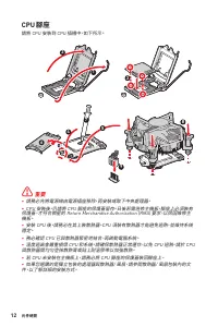
12 元件總覽 CPU 腳座 請將 CPU 安裝到 CPU 插槽中,如下所示。 ⚠ 重要 ∙ 請務必先將電源線由電源插座移除,再安裝或取下中央處理器。 ∙ CPU 安裝後,仍請將 CPU 腳座的保護蓋留存。日後若需送修主機板,腳座上必須裝有 保護蓋,才符合微星的 Return Merchandise Authorization (RMA) 要求,以保固維修主 機板。 ∙ 安裝 CPU 後,請務必在其上裝散熱器。CPU 須裝有散熱器才能避免過熱,並維持系統 穩定。 ∙ 務必確認 CPU 已與散熱器緊密地結合,再啟動電腦系統。 ∙ 溫度過高會嚴重損壞 CPU 和系統。請確保散熱器正常運作,以免 C...
Page 181 - 記憶體插槽; 記憶體模組安裝建議
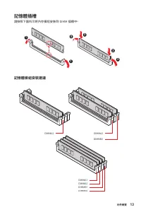
13 元件總覽 元件總覽 記憶體插槽 請按照下圖所示將內存模組安裝到 DIMM 插槽中。 DIMMB2 DIMMA2 DIMMA2 記憶體模組安裝建議 DIMMB2 DIMMB1 DIMMA2 DIMMA1 1 1 2 3 3 2
Page 187 - JTBT1: Thunderbolt 擴充卡接頭
19 元件總覽 元件總覽 JUSB1: USB 3.2 Gen 2 Type-C 接頭 這個接頭可供連接前面板上的 USB 3.2 Gen2 Type-C 接頭,這個接頭具有防呆設計。請 務必以相應的方向連接線纜。 JUSB1 USB Type-C 線纜 前面板上的 USB Type-C 連接埠 JTBT1: Thunderbolt 擴充卡接頭 此接頭用於連接 Thunderbolt I/O 擴充卡。 1 2 16 15 1 TBT_Force_PWR 2 TBT_S0IX_Entry_REQ 3 TBT_CIO_Plug_Event# 4 TBT_S0IX_Entry_ACK 5 SLP_S...
Page 189 - 使用機殼開啟偵測器
21 元件總覽 元件總覽 JCI1: 機殼開啟接頭 此接頭可連接機殼開啟開關排線。 一般 (預設值) 觸動機殼開啟事件 使用機殼開啟偵測器 1. 連接 JCI1 插孔和機殼上的機殼開啟開關/感測器。 2. 關閉機殼蓋。 3. 前往 BIOS > SETTINGS > Security > Chassis Intrusion Configuration。 4. 將 Chassis Intrusion 設定為 Enabled 。 5. 按下 F10 儲存並離開,然後按 Enter 鍵選擇 Yes 。 6. 之後若機殼蓋再次被開啟,電腦啟動後畫面上即會顯示警告訊息。 重設機殼開啟警...
Page 190 - 重設 BIOS 至預設值
22 元件總覽 JBAT1: 清除 CMOS (重置 BIOS) 功能跳線 主機板內建 CMOS 記憶體,是利用主機板上的外接電池來保留系統設定。若要清除系統 設定,請將跳線設為清除 CMOS 記憶體。 保留資料 (預設值) 清除 CMOS/ 重置 BIOS 重設 BIOS 至預設值 1. 關閉電腦電源並拔除電源線。 2. 使用跳接器蓋讓 JBAT1 短路持續約 5-10 秒。 3. 將跳接器蓋從 JBAT1 上取出。 4. 插入電源線並開啟電腦電源。 JRAINBOW1~2: 可定址 RGB LED 接頭 JRAINBOW 接頭允許您連接 WS2812B 可定址 RGB LED 燈條 5V。...
Page 191 - 除錯 LED 指示燈
23 元件總覽 元件總覽 除錯 LED 指示燈 這些 LED 指示燈顯示主機板的狀態。 CPU - 表示未偵測到 CPU 或已故障。 DRAM - 表示未偵測到記憶體或已故障。 VGA - 表示未偵測到顯示晶片或已故障。 BOOT - 表示未偵測到開機裝置或已故障。 JRGB1: RGB LED 接頭 JRGB 接頭允許您連接 5050 RGB LED 燈條 (12V)。 ⚠ 重要 ∙ JRGB 接頭支援最長 2 公尺的 5050 RGB LED 燈條 (12V/G/R/B),最大額定功率為 3A (12V)。 ∙ 進行安裝或拔除 RGB LED 燈條前,請先關閉電源供應器,並將電源線由電源插...
Page 192 - 安裝操作系統、驅動程式和 MSI Center; 安裝 Windows; 安裝驅動程式; MSI Center 使用者指南
24 安裝操作系統、驅動程式和 MSI Center 安裝操作系統、驅動程式和 MSI Center 請通過 www.msi.com下載並更新最新的公用程式和驅動程式 安裝 Windows ® 10 1. 啟動電腦。 2. 將 Windows® 10 安裝光碟/ USB 置入電腦。 3. 按電腦機殼上的 重新啟動 按鈕。 4. 在電腦開機自我測試 (POST) 期間,按 F11 鍵進入開機功能表。 5. 在開機功能表中選擇光碟機。 6. 畫面顯示 Press any key to boot from CD or DVD... 訊息時,按任意鍵。 7. 依照畫面指示,安裝 Windows® 10...
Page 194 - 進入 BIOS 設定; 功能鍵; BIOS 使用者指南
26 UEFI BIOS BIOS 設定 預設值提供最佳效能,可在一般情況下達到系統穩定度。除非您熟悉 BIOS 設定,否則 請 務必使用預設值 ,以免系統受損或開機失敗。 ⚠ 重要 ∙ BIOS 項目會持續更新達到更優異的系統效能。因此,說明內容可能會與最新的 BIOS 稍微不同,因此僅供參考。您亦可參閱 HELP 取得 BIOS 項目說明。 ∙ 本節的圖片僅供參考,可能與您所購買的產品有所不同。 進入 BIOS 設定 開機過程中畫面出現 按 DEL 鍵進入設定功能表,按 F11 進入開機功能表 時,按 Delete 鍵進入設定功能表。 功能鍵 F1 : 一般說明 F2 : 添加/刪除收藏項...
Page 195 - 重設 BIOS
27 UEFI BIOS UEFI BIOS 重設 BIOS 某些情況下,您可能會需要將 BIOS 復原為出廠預設值,以解決部份特定問題。有多種方 法可重設 BIOS: ∙ 前往 BIOS,然後按 F6 載入最佳化預設值。 ∙ 將主機板上的清除 CMOS 功能跳線短路。 ∙ 按下背板 I/O 上的清除 CMOS 按鈕。 ⚠ 重要 在清除 CMOS 數據之前,請確保計算機已關閉。 請參閱清除 CMOS 跳線/ 按鈕部分以重 置 BIOS。 更新 BIOS 以 M-FLASH 更新 BIOS 更新前:請從 MSI 網站下載符合您主機板型號的最新 BIOS 檔案。然後將 BIOS 檔案存到 USB ...
Page 196 - 以 MSI Center 更新 BIOS
28 UEFI BIOS 以 MSI Center 更新 BIOS 更新前準備: ∙ 確保已經安裝網路驅動程式,且已正確設定網際網路連線。 ∙ 請在更新 BIOS 之前,關閉其他所有應用程式軟體。 進行更新 BIOS: 1. 安裝並開啟 MSI CENTER 並進入 Support 頁面。 2. 選取 Live Update 並按一下 Advanced 按鈕。 3. 選取 BIOS 檔案並按一下 Install 按鈕。 4. 安裝提示出現後,按一下 Install 按鈕。 5. 系統將自動重啟以更新 BIOS。 6. 更新進度 100% 完成後,系統會自動重新啟動。 以 Flash BIOS ...
Page 197 - 目次; この度はMSI®
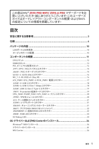
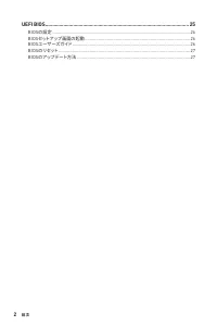
1 <變數 1> 目次 目次 安全に関する注意事項 ..................................................................................... 3 仕様 .................................................................................................................. 4 パッケージの内容 ......................................................
Page 199 - 安全に関する注意事項
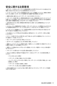
3 目次 安全に関する注意事項 安全に関する注意事項 ∙ 本パッケージ内のコンポーネントは静電放電(ESD)を受けやすいので、PCの組み立てを 確実に成功させるために以下の注意事項を守ってください。 ∙ コンポーネントがしっかりと全部接続され手いることを確認してください。確実に接続さ れていない場合、コンポーネントの認識不良や起動不良の原因となります。 ∙ 繊細な部品に触れないよう、マザーボードのフチを持ってください。 ∙ マザーボードを扱う際には、静電気破壊を防ぐために、静電放電 (ESD)リストストラップ を着けることをお薦めします。ESDリストストラップが用意できない場合は、他の金属製の...
Page 200 - 仕様
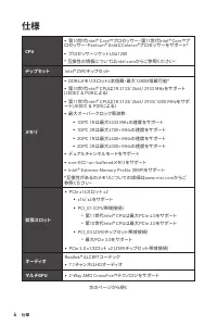
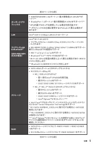
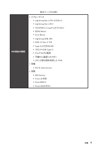
4 仕様 仕様 CPU ∙ 第10世代Intel® Core™プロセッサー、第11世代Intel® Core™プ ロセッサー、Pentium® GoldとCeleron®プロセッサーをサポート* ∙ プロセッサーソケットLGA1200 * 互換性の情報についてはintel.comからご参照ください。 チップセット Intel® Z590チップセット メモリ ∙ DDR4メモリスロット4本搭載、最大128GB搭載可能* ∙ 第10世代Intel® CPUは1R 2133/ 2666/ 2933 MHzをサポート (JEDEC & PORによる) ∙ 第11世代Intel® CPUは1R ...
Page 206 - パッケージの内容; LANポートLED状態表; オーディオポートの配置
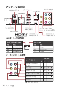
10 パッケージの内容 パッケージの内容 リンク/ アクティビティLED 状態 解説 Off リンクしていません 黄色 リンクしています 点滅 データ通信中です スピードLED 状態 解説 Off 10 Mbps 緑色 100/ 1000 Mbps オレンジ 2.5 Gbps LANポートLED状態表 USB 3.2 Gen 1 5Gbps Type-A Flash BIOSボタン PS/2コンボポート 2.5 Gbps LAN DisplayPort USB 2.0 Type-A USB 2.0 Type-A オーディオポート Wi-Fiアンテナ コネクター (Z590 PRO WIFIのみ...
Page 207 - コンポーネントの概要
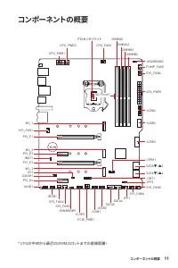
11 パッケージの内容 コンポーネントの概要 コンポーネントの概要 * CPUの中央から最近のDIMMスロットまでの直線距離。 SATA6 SATA5 SYS_FAN5 SYS_FAN4 JCOM1 JTBT1 JFP2 JTPM1 JRGB1 SATA▼1▲2 SATA▼3▲4 JCI1 M2_3 M2_2 M2_1 SYS_FAN1 JUSB4 JUSB5 JUSB3 JUSB1 JUSB2 PCIE_PWR1 SYS_FAN3 SYS_FAN2 CPU_FAN1 SYS_FAN6 PUMP_FAN1 PCI_E1 PCI_E2 PCI_E3 JBAT1 PCI_E4 JDASH1 プロセ...
Page 208 - CPUソケット
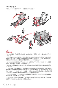
12 コンポーネントの概要 CPUソケット 下図のようにCPUをCPUソケットに取り付けてください。 ⚠ 注意 ∙ CPUの脱着は、必ず電源をオフにし、コンセントから電源ケーブルを抜いてから行って ください。 ∙ CPUを取り付けた後、CPUソケットに取り付けられていたCPUソケットカバーは絶対に 捨てないでください。本製品の修理を依頼される際に、CPUソケットカバーがCPUソケット に取り付けられていない場合は修理をお断りすることがございます。 ∙ CPUを取り付ける際は、必ずCPUクーラーも取り付けてください。CPUクーラーは過熱 を防ぎ、システムの安定を保つために必要です。 ∙ システム...
Page 209 - DIMMスロット; メモリモジュールの推奨取付順序
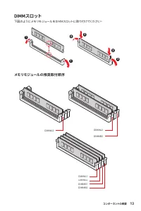
13 コンポーネントの概要 コンポーネントの概要 DIMMスロット 下図のようにメモリモジュールをDIMMスロットに取り付けてください。 DIMMB2 DIMMA2 DIMMA2 メモリモジュールの推奨取付順序 DIMMB2 DIMMB1 DIMMA2 DIMMA1 1 1 2 3 3 2
Page 211 - JFP1、JFP2: フロントパネルコネクター; JAUD1: フロントオーディオコネクター
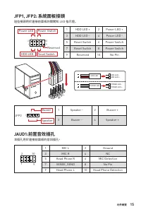
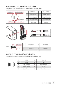
15 コンポーネントの概要 コンポーネントの概要 JFP1、JFP2: フロントパネルコネクター これらのコネクターにはフロントパネルのスイッチとLEDを接続します。 1 2 10 9 + + + - - - - + Power LED HDD LED Reset Switch Reserved Power Switch 1 HDD LED + 2 Power LED + 3 HDD LED - 4 Power LED - 5 Reset Switch 6 Power Switch 7 Reset Switch 8 Power Switch 9 Reserved 10 No Pin JFP2 ...
Page 215 - JTBT1: Thunderbolt追加カードコネクター
19 コンポーネントの概要 コンポーネントの概要 JUSB1: USB 3.2 Gen 2 Type-Cコネクター このコネクターにはフロントパネルのUSB 3.2 Gen 2 Type-Cコネクターを接続します。こ のコネクターは確実なデザインを持っています。ケーブルを接続すると、対応方向で接続す ることを確認してください。 JUSB1 USB Type-Cケーブル フロントパネルのUSB Type-Cポート JTBT1: Thunderbolt追加カードコネクター このコネクターは追加のThunderbolt I/Oカードを接続します。 1 2 16 15 1 TBT_Force_PWR ...
Page 217 - ケース開放検知機能の使い方; JDASH1: チューニングコントローラーコネクター
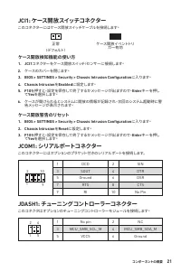
21 コンポーネントの概要 コンポーネントの概要 JCI1: ケース開放スイッチコネクター このコネクターにはケース開放スイッチケーブルを接続します。 正常 (デフォルト) ケース開放イベントトリ ガー有効 ケース開放検知機能の使い方 1. JCI1 コネクターをケース開放スイッチ/センサーに接続します。 2. ケースのカバーを閉じます。 3. BIOS > SETTINGS > Security > Chassis Intrusion Configuration に入ります。 4. Chassis Intrusion を Enabled に設定します。 5. F10 を押す...
Page 218 - BIOSをデフォルト値にリセットする
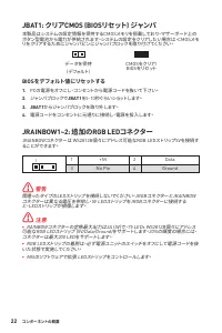
22 コンポーネントの概要 JBAT1: クリアCMOS (BIOSリセット) ジャンパ 本製品はシステムの設定情報を保持するCMOSメモリを搭載しており、マザーボード上の ボタン型電池から電力が供給されます。システムの設定をクリアしたい場合は、CMOSメモ リをクリアするためにジャンパピンにジャンパブロックを取り付けてください。 データを保持 (デフォルト) CMOSをクリア/ BIOSをリセット BIOSをデフォルト値にリセットする 1. PCの電源をオフにし、コンセントから電源コードを抜いて下さい。 2. ジャンパブロックで JBAT1 を5-10秒ぐらいショットします。 3. JBAT...
Page 220 - OS、ドライバーおよびMSI Centerのインストール; Windows® 10のインストール; ドライバーのインストール; MSI Centerユーザーズガイド
24 OS、ドライバーおよびMSI Centerのインストール OS、ドライバーおよびMSI Centerのインストール www.msi.comから最新のユーティリティとドライバーをダウンロードしてアップデートし てください。 Windows® 10のインストール 1. PCの電源をオンにします。 2. Windows ® 10のインストールメディアを光学ドライブに挿入します。 3. PCケースの Restart ボタンを押します。 4. POST (Power-On Self Test)中に F11 キーを押し、ブートメニューに入ります。 5. ブートメニューから光学ドライブを選択します。 ...
Page 222 - BIOSセットアップ画面の起動; 機能キー; BIOSユーザーズガイド
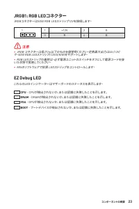
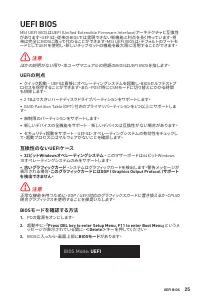
26 UEFI BIOS BIOSの設定 BIOSのデフォルト設定は、通常の使用においてシステムの安定性のために最適な性能を 提供します。ユーザーがBIOSに精通していない場合は、起こり得るシステムへのダメージ や起動の失敗を防ぐために、 常にデフォルト設定のまま にすべきです。 ⚠ 注意 ∙ BIOSは性能の向上のために、継続的に変更と修正が行われています。最新のBIOSと本 書の内容に齟齬が発生してしまう場合があります。あらかじめご承知おきください。BIOS の設定項目の詳細は HELP 情報パネルを参照してください。 ∙ BIOSの画面、オプション、設定はシステムにより異なる場合がありま...
Page 223 - BIOSのリセット; BIOSのアップデート方法
27 UEFI BIOS UEFI BIOS BIOSのリセット 特定の問題を解決するために、BIOSをセフォルト設定に戻す必要があります。BIOSのリセ ットにはいくつかの方法があります。 ∙ BIOSセットアップ画面で <F6> キーを押してoptimized defaultsをロードする。 ∙ マザーボード上のクリアCMOS ジャンパをショートする。 ∙ リアI/OパネルのクリアCMOSボタンを押す。 ⚠ 注意 CMOSデータをクリアする前に、必ずPCの電源がオフにすることを確認してください。BIOS のリセットについてはクリアCOMSジャンパセクションをご参照ください。 B...
Page 224 - MSI CenterでのBIOSアップデート
28 UEFI BIOS MSI CenterでのBIOSアップデート アップデートの前に: ∙ LANドライバーがインストールされ、インターネット接続が正しく設定されていることを 確認してください。 ∙ アップデートする前に、他のアプリケーションソフトをすべて閉じてください。 BIOSのアップデート: 1. MSI Centerをインストールして起動させて、 Support ページに入ります。 2. Live Update を選択して、 Advance ボタンをクリックします。 3. BIOSファイルを選択して、 Install ボタンをクリックします。 4. インストールのリマインダーが表...
Page 225 - FCC Compliance Statement; CE Conformity; Regulatory Notices
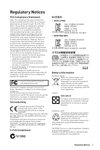
i <變數 1> Regulatory Notices FCC Compliance Statement Note: This equipment has been tested and found to comply with the limits for a Class B digital device, pursuant to part 15 of the FCC Rules. These limits are designed to provide reasonable protection against harmful interference in a residen...
Page 226 - ii; WEEE (Waste Electrical and
ii Regulatory Notices WEEE (Waste Electrical and Electronic Equipment) Statement ENGLISH To protect the global environment and as an environmentalist, MSI must remind you that... Under the European Union (“EU”) Directive on Waste Electrical and Electronic Equipment, Directive 2002/96/EC, which takes...
Page 227 - iii
iii Regulatory Notices Regulatory Notices SRPSKI Da bi zaštitili prirodnu sredinu, i kao preduzeće koje vodi računa o okolini i prirodnoj sredini, MSI mora da vas podesti da… Po Direktivi Evropske unije (“EU”) o odbačenoj ekektronskoj i električnoj opremi, Direktiva 2002/96/EC, koja stupa na snagu o...
Page 229 - Copyright
v Regulatory Notices Regulatory Notices Copyright Micro-Star Int’l Co.,Ltd. Copyright © 2021 All rights reserved. The MSI logo used is a registered trademark of Micro-Star Int’l Co., Ltd. All other marks and names mentioned may be trademarks of their respective owners. No warranty as to accuracy or ...


 MSI PRO H610M-E DDR4 User Manual
 MSI PRO H610M-G DDR4 User Manual
 MSI PRO X670-P User Manual
 MSI PRO Z690-A DDR4 User Manual
 MSI Z490 User Manual
 MSI Z490-A PRO User Manual
 MSI Z690 User Manual
 MSI A520 User Manual
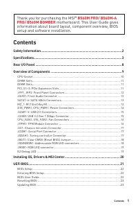 MSI B560 User Manual
 MSI B560M BOMBER User Manual
 MSI B560M PRO-E User Manual
 MSI B660 User Manual
 MSI B660M User Manual