Page 2 - II; processeur/ Установка процессора
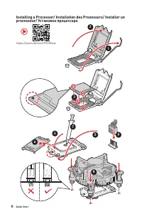
II Quick Start Installing a Processor/ Installation des Prozessors/ Installer un processeur/ Установка процессора ⚽ https://youtu.be/4ce91YC3Oww 1 2 3 6 4 5 7 8 9
Page 3 - III; Installer une mémoire DDR4/ Установка памяти DDR4
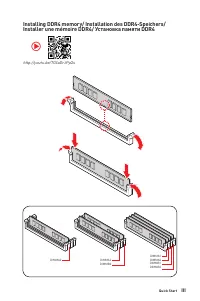
III Quick Start Installing DDR4 memory/ Installation des DDR4-Speichers/ Installer une mémoire DDR4/ Установка памяти DDR4 http://youtu.be/T03aDrJPyQs ⚽ DIMMA2 DIMMA2 DIMMB2 DIMMA1 DIMMA2 DIMMB1 DIMMB2
Page 4 - IV; Connecting the Front Panel Header/ Anschließen der; HDD LED
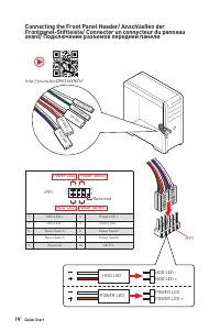
IV Quick Start Connecting the Front Panel Header/ Anschließen der Frontpanel-Stiftleiste/ Connecter un connecteur du panneau avant/ Подключение разъемов передней панели http://youtu.be/DPELIdVNZUI HDD LED RESET SW JFP1 HDD LED HDD LED - HDD LED + POWER LED - POWER LED + POWER LED 1 2 10 9 + + + - - ...
Page 5 - Installing the Motherboard/ Installation des Motherboards/
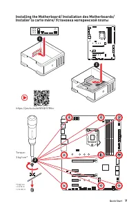
V Quick Start Installing the Motherboard/ Installation des Motherboards/ Installer la carte mère/ Установка материнской платы 3 https://youtu.be/wWI6Qt51Wnc ⚽ Torque:3 kgf·cm* *3 kgf·cm = 0.3 N·m = 2.6 lbf·in 2 1
Page 6 - Connecting the Power Connectors/ Stromanschlüsse
VI Quick Start http://youtu.be/gkDYyR_83I4 ⚽ ATX_PWR1 CPU_PWR1 CPU_PWR2 Connecting the Power Connectors/ Stromanschlüsse anschliessen/ Connecter les câbles du module d’alimentation/ Подключение разъемов питания
Page 7 - VII; Installer le disque dur SATA/ Установка дисков SATA
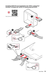
VII Quick Start Installing SATA Drives/ Installation der SATA-Laufwerke/ Installer le disque dur SATA/ Установка дисков SATA http://youtu.be/RZsMpqxythc 1 2 3 4 5 ⚽
Page 8 - VIII; Installing a Graphics Card/ Einbau der Grafikkarte/ Installer
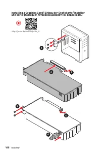
VIII Quick Start 1 http://youtu.be/mG0GZpr9w_A 2 3 4 5 6 Installing a Graphics Card/ Einbau der Grafikkarte/ Installer une carte graphique/ Установка дискретной видеокарты ⚽
Page 9 - IX; Connecting Peripheral Devices/ Peripheriegeräte/ Connecter
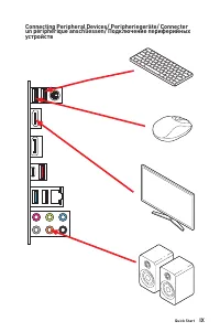
IX Quick Start Connecting Peripheral Devices/ Peripheriegeräte/ Connecter un périphérique anschliessen/ Подключение периферийных устройств
Page 10 - питания
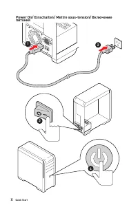
X Quick Start 4 3 1 2 Power On/ Einschalten/ Mettre sous-tension/ Включение питания
Page 11 - Contents
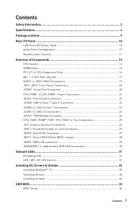
1 Contents Contents Safety Information ................................................................................................. 3Specifications ......................................................................................................... 4Package contents ..........................
Page 13 - Safety Information
3 Safety Information Safety Information ∙ The components included in this package are prone to damage from electrostatic discharge (ESD). Please adhere to the following instructions to ensure successful computer assembly. ∙ Ensure that all components are securely connected. Loose connections may cau...
Page 14 - Specifications; Supports Dual-Channel mode
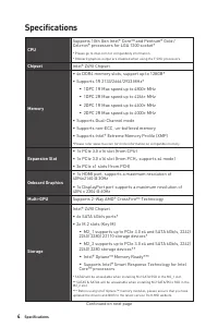
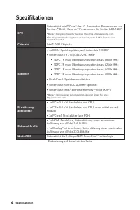
4 Specifications Specifications CPU Supports 10th Gen Intel® Core™ and Pentium® Gold / Celeron® processors for LGA 1200 socket* * Please go to intel.com for compatibility information.* Onboard graphics output are disabled when using the F SKU processors. Chipset Intel® Z490 Chipset Memory ∙ 4x DDR4 ...
Page 16 - Internal Connectors; LED Features
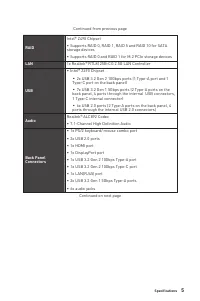
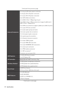
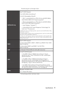
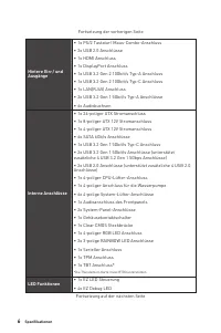
6 Specifications Continued from previous page Internal Connectors ∙ 1x 24-pin ATX main power connector ∙ 1x 8-pin ATX 12V power connector ∙ 1x 4-pin ATX 12V power connector ∙ 6x SATA 6Gb/s connectors ∙ 1x USB 3.2 Gen 1 5Gbps Type-C port ∙ 2x USB 3.2 Gen 1 5Gbps connectors (support additional 4 USB 3...
Page 17 - Software; Special Features
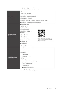
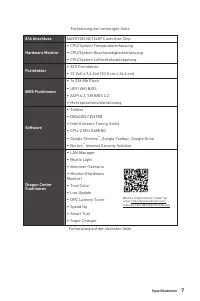
7 Specifications Continued from previous page Software ∙ Drivers ∙ DRAGON CENTER ∙ Intel Extreme Tuning Utility ∙ CPU-Z MSI GAMING ∙ Google Chrome™, Google Toolbar, Google Drive ∙ Norton™ Internet Security Solution Dragon Center Features ∙ LAN Manager ∙ Mystic Light ∙ User Scenario ∙ Monitor(Hardwar...
Page 18 - Multi GPU-CrossFire Technology
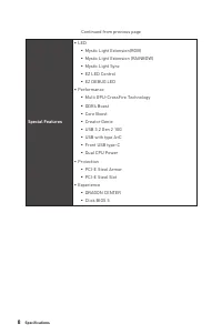
8 Specifications Continued from previous page Special Features ∙ LED ▪ Mystic Light Extension(RGB) ▪ Mystic Light Extension (RAINBOW) ▪ Mystic Light Sync ▪ EZ LED Control ▪ EZ DEBUG LED ∙ Performance ▪ Multi GPU-CrossFire Technology ▪ DDR4 Boost ▪ Core Boost ▪ Creator Genie ▪ USB 3.2 Gen 2 10G ▪ USB...
Page 19 - Package contents; Motherboard; Case stand-off notification; Application; Driver DVD; Cables; Case badge; Important
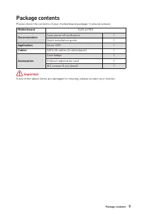
9 Package contents Package contents Please check the contents of your motherboard package. It should contain: Motherboard Z490-A PRO Documentation Case stand-off notification 1 Quick installation guide 1 Application Driver DVD 1 Cables SATA 6G cables (2 cables/pack) 1 Accessories Case badge 1 Produc...
Page 20 - Speed LED; LAN Port LED Status Table; Audio Ports
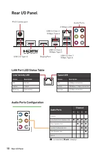
10 Rear I/O Panel Rear I/O Panel PS/2 Combo port 2.5Gbps LAN USB 2.0 Type-A DisplayPort Audio Ports USB 3.2 Gen 2 10Gbps Type A USB 3.2 Gen 1 5Gbps Type A USB 3.2 Gen 2 10Gbps Type C Link/ Activity LED Status Description Off No link Yellow Linked Blinking Data activity Speed LED Status Description O...
Page 21 - Realtek Audio Console; better sound experience.; Auto popup dialog; which device is current connected.
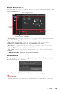
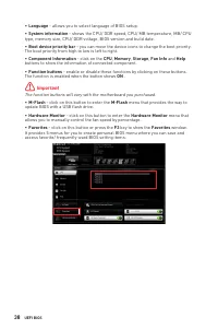
11 Rear I/O Panel Realtek Audio Console After Realtek Audio Console is installed. You can use it to change sound settings to get better sound experience. ∙ Device Selection - allows you to select a audio output source to change the related options. The check sign indicates the devices as default. ∙ ...
Page 22 - Audio jacks to headphone and microphone diagram
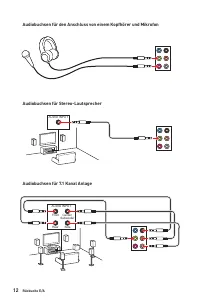
12 Rear I/O Panel AUDIO INPUT Rear Front Side Center/ Subwoofer AUDIO INPUT Audio jacks to headphone and microphone diagram Audio jacks to stereo speakers diagram Audio jacks to 7.1-channel speakers diagram
Page 23 - Overview of Components
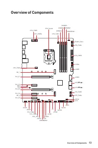
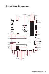
13 Overview of Components Overview of Components DIMMA1 CPU_FAN1 DIMMA2 DIMMB1 DIMMB2 JRAINBOW1 PUMP_FAN1SYS_FAN6 SYS_FAN5 SYS_FAN1 SYS_FAN4 JRTD3 JFP1 JTBT1 SATA6 SATA5 JTPM1 JUSB1 JT1 JUSB2 JFP2 JCOM1 LED_SW1 JRAINBOW2 ATX_PWR1 JUSB4 JUSB5 JUSB3 CPU Socket CPU_PWR1 CPU_PWR2 SATA▼1▲2 SATA▼3▲4 SYS_F...
Page 24 - CPU Socket; Introduction to the LGA 1200 CPU; notches
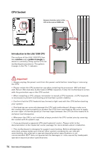
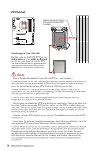
14 Overview of Components ⚠ Important ∙ Always unplug the power cord from the power outlet before installing or removing the CPU. ∙ Please retain the CPU protective cap after installing the processor. MSI will deal with Return Merchandise Authorization (RMA) requests if only the motherboard comes wi...
Page 25 - DIMM Slots; Memory module installation recommendation; Always insert memory modules in the; DRAM Frequency; to set the memory
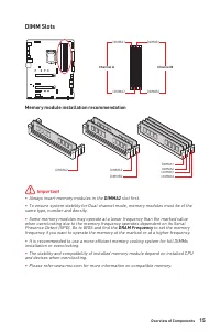
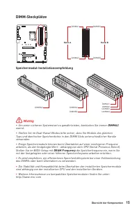
15 Overview of Components DIMM Slots DIMMA1 DIMMB1 Channel A Channel B DIMMA2 DIMMB2 Memory module installation recommendation ⚠ Important ∙ Always insert memory modules in the DIMMA2 slot first. ∙ To ensure system stability for Dual channel mode, memory modules must be of the same type, number and ...
Page 26 - MSI; to support its weight to prevent deformation of
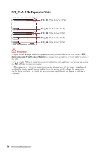
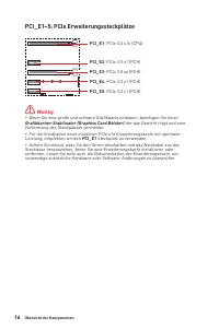
16 Overview of Components PCI_E1~5: PCIe Expansion Slots ⚠ Important ∙ If you install a large and heavy graphics card, you need to use a tool such as MSI Gaming Series Graphics Card Bolster to support its weight to prevent deformation of the slot. ∙ For a single PCIe x16 expansion card installation ...
Page 27 - Intel® RST only supports PCIe M.2 SSD with UEFI ROM.; Video Demonstration; Watch the video to learn how to Install; Installing M.2 module
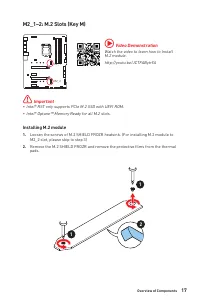
17 Overview of Components M2_1~2: M.2 Slots (Key M) M2_1 M2_2 ⚠ Important ∙ Intel® RST only supports PCIe M.2 SSD with UEFI ROM. ∙ Intel® Optane™ Memory Ready for all M.2 slots. ⚽ Video Demonstration Watch the video to learn how to Install M.2 module.http://youtu.be/JCTFABytrYA 1 1 2 Installing M.2 ...
Page 28 - Standoff
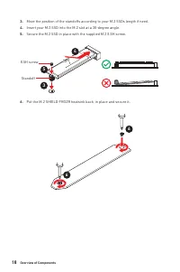
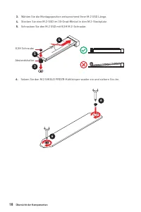
18 Overview of Components 30º 30º 5 4 3 8.5H screw Standoff 3. Move the position of the standoffs according to your M.2 SSDs length if need. 4. Insert your M.2 SSD into the M.2 slot at a 30-degree angle. 5. Secure the M.2 SSD in place with the supplied M.2 8.5H screw. 6. Put the M.2 SHIELD FROZR hea...
Page 29 - Slot
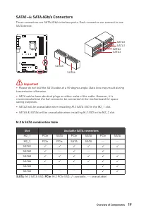
19 Overview of Components SATA1~6: SATA 6Gb/s Connectors These connectors are SATA 6Gb/s interface ports. Each connector can connect to one SATA device. ⚠ Important ∙ Please do not fold the SATA cable at a 90-degree angle. Data loss may result during transmission otherwise. ∙ SATA cables have identi...
Page 30 - JCOM1: Serial Port Connector
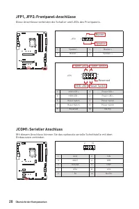
20 Overview of Components JFP1, JFP2: Front Panel Connectors These connectors connect to the switches and LEDs on the front panel. 1 2 10 9 + + + - - - - + Power LED HDD LED Reset Switch Reserved Power Switch JFP1 1 HDD LED + 2 Power LED + 3 HDD LED - 4 Power LED - 5 Reset Switch 6 Power Switch 7 Re...
Page 31 - supply to ensure stable operation of the motherboard.
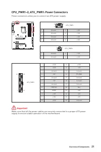
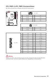
21 Overview of Components 24 13 1 12 ATX_PWR1 1 +3.3V 13 +3.3V 2 +3.3V 14 -12V 3 Ground 15 Ground 4 +5V 16 PS-ON# 5 Ground 17 Ground 6 +5V 18 Ground 7 Ground 19 Ground 8 PWR OK 20 Res 9 5VSB 21 +5V 10 +12V 22 +5V 11 +12V 23 +5V 12 +3.3V 24 Ground 5 4 1 8 CPU_PWR1 1 Ground 5 +12V 2 Ground 6 +12V 3 Gr...
Page 32 - JAUD1: Front Audio Connector; sure to connect it with the corresponding orientation.
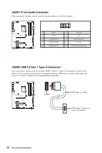
22 Overview of Components JAUD1: Front Audio Connector This connector allows you to connect audio jacks on the front panel. 1 2 10 9 1 MIC L 2 Ground 3 MIC R 4 NC 5 Head Phone R 6 MIC Detection 7 SENSE_SEND 8 No Pin 9 Head Phone L 10 Head Phone Detection JUSB5: USB 3.2 Gen 1 Type-C Connector This co...
Page 34 - MSI® DRAGON CENTER utility.; JTPM1: TPM Module Connector; platform manual for more details and usages.
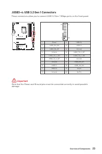
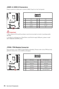
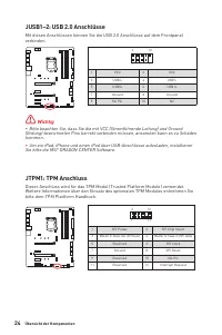
24 Overview of Components JUSB1~2: USB 2.0 Connectors These connectors allow you to connect USB 2.0 ports on the front panel. 1 2 10 9 1 VCC 2 VCC 3 USB0- 4 USB1- 5 USB0+ 6 USB1+ 7 Ground 8 Ground 9 No Pin 10 NC ⚠ Important ∙ Note that the VCC and Ground pins must be connected correctly to avoid pos...
Page 35 - Default DC Mode fan connectors; HARDWARE MONITOR; Pin definition of fan connectors
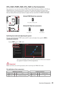
25 Overview of Components CPU_FAN1, PUMP_FAN1, SYS_FAN1~6: Fan Connectors Fan connectors can be classified as PWM (Pulse Width Modulation) Mode or DC Mode. PWM Mode fan connectors provide constant 12V output and adjust fan speed with speed control signal. DC Mode fan connectors control fan speed by ...
Page 36 - JCI1: Chassis Intrusion Connector; Using chassis intrusion detector
26 Overview of Components JCI1: Chassis Intrusion Connector This connector allows you to connect the chassis intrusion switch cable. Normal (default) Trigger the chassis intrusion event Using chassis intrusion detector 1. Connect the JCI1 connector to the chassis intrusion switch/ sensor on the chas...
Page 37 - JRTD3: Intel RTD3 Connector
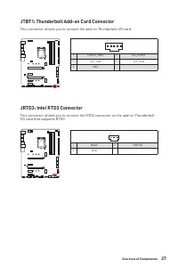
27 Overview of Components JTBT1: Thunderbolt Add-on Card Connector This connector allows you to connect the add-on Thunderbolt I/O card. JRTD3: Intel RTD3 Connector This connector allows you to connect the RTD3 connector on the add-on Thunderbolt I/O card that supports RTD3. 1 1 FORCE_PWR 2 SCI_EVEN...
Page 38 - Resetting BIOS to default values
28 Overview of Components JBAT1: Clear CMOS (Reset BIOS) Jumper There is CMOS memory onboard that is external powered from a battery located on the motherboard to save system configuration data. If you want to clear the system configuration, set the jumpers to clear the CMOS memory. Keep Data (defau...
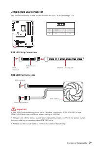
Page 39 - before installing or removing the RGB LED strip.; JRGB1: RGB LED connector; RGB LED Strip Connection
29 Overview of Components ⚠ Important ∙ The JRGB connector supports up to 2 meters continuous 5050 RGB LED strips (12V/G/R/B) with the maximum power rating of 3A (12V). ∙ Always turn off the power supply and unplug the power cord from the power outlet before installing or removing the RGB LED strip....
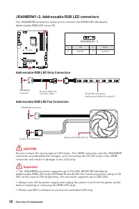
Page 40 - CAUTION; connector will result in damage to the LED strip.; JRAINBOW1~2: Addressable RGB LED connectors; Addressable RGB LED strips 5V.; Addressable RGB LED Strip Connection
30 Overview of Components 1 1 1 D +5V ⚠ CAUTION Do not connect the wrong type of LED strips. The JRGB connector and the JRAINBOW connector provide different voltages, and connecting the 5V LED strip to the JRGB connector will result in damage to the LED strip. ⚠ Important ∙ The JRAINBOW connector su...
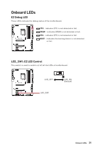
Page 41 - EZ Debug LED; These LEDs indicate the debug status of the motherboard.; CPU; - indicates CPU is not detected or fail.; DRAM; - indicates DRAM is not detected or fail.; VGA; - indicates GPU is not detected or fail.; BOOT; - indicates the booting device is not detected; Onboard LEDs; This switch is used to switch on/ off all the LEDs of motherboard.
31 Onboard LEDs EZ Debug LED These LEDs indicate the debug status of the motherboard. CPU - indicates CPU is not detected or fail. DRAM - indicates DRAM is not detected or fail. VGA - indicates GPU is not detected or fail. BOOT - indicates the booting device is not detected or fail. Onboard LEDs LED...
Page 42 - Installing Windows® 10; key during the computer POST (Power-On Self Test) to get into Boot; Installing Drivers; Installing Utilities; button in the lower-right corner of the window.
32 Installing OS, Drivers & Utilities Installing OS, Drivers & Utilities Please download and update the latest utilities and drivers at www.msi.com Installing Windows® 10 1. Power on the computer. 2. Insert the Windows® 10 installation disc/USB into your computer. 3. Press the Restart button...
Page 43 - UEFI BIOS; 2-bit Windows operating system; - this motherboard supports only 64-bit Windows; Older graphics card; - the system will detect your graphics card. When display a; There is no GOP (Graphics Output protocol) support detected in; UEFI boot mode
33 UEFI BIOS UEFI BIOS MSI UEFI BIOS is compatible with UEFI (Unified Extensible Firmware Interface) architecture. The UEFI BIOS firmware infrastructure has many new functions and advantages that traditional BIOS cannot achieve. It will fully support future PCs and devices that comply with UEFI firm...
Page 44 - BIOS Setup; always keep the default settings; HELP; Entering BIOS Setup; Delete; Function key
34 UEFI BIOS BIOS Setup The default settings offer the optimal performance for system stability in normal conditions. You should always keep the default settings to avoid possible system damage or failure booting unless you are familiar with BIOS. ⚠ Important ∙ BIOS items are continuously update for...
Page 45 - Resetting BIOS; Updating BIOS; Updating BIOS with M-FLASH
35 UEFI BIOS Resetting BIOS You might need to restore the default BIOS setting to solve certain problems. There are several ways to reset BIOS: ∙ Go to BIOS and press F6 to load optimized defaults. ∙ Short the Clear CMOS jumper on the motherboard. ⚠ Important Be sure the computer is off before clear...
Page 46 - Updating the BIOS with MSI DRAGON CENTER
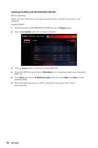
36 UEFI BIOS Updating the BIOS with MSI DRAGON CENTER Before updating:Make sure the LAN driver is already installed and the internet connection is set properly. Updating BIOS: 1. Install and launch MSI DRAGON CENTER and go to Support page. 2. Select Live Update and click on Advance button. 3. Click ...
Page 47 - EZ Mode; - click on it to toggle the CREATOR GENIE for performance; - allows you to select the XMP profile for memory to overclock. This
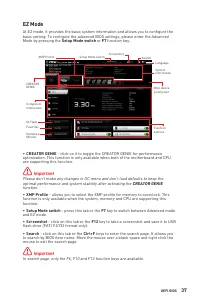
37 UEFI BIOS EZ Mode At EZ mode, it provides the basic system information and allows you to configure the basic setting. To configure the advanced BIOS settings, please enter the Advanced Mode by pressing the Setup Mode switch or F7 function key. XMP Profile Component Information System information ...
Page 49 - To add a BIOS item to a favorite menu; Select a BIOS item not only on BIOS menu but also on search page.; To delete a BIOS item from favorite menu; Select a BIOS item on favorite menu.; and click on; OK
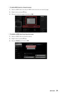
39 UEFI BIOS ▪ To add a BIOS item to a favorite menu 1. Select a BIOS item not only on BIOS menu but also on search page. 2. Right-click or press F2 key. 3. Choose a favorite page and click on OK. ▪ To delete a BIOS item from favorite menu 1. Select a BIOS item on favorite menu. 2. Right-click or pr...
Page 50 - Advanced Mode; Press; may get better performance.
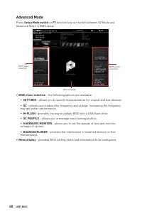
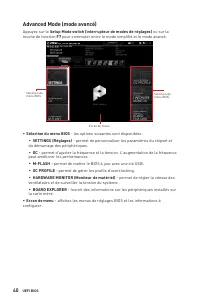
40 UEFI BIOS Advanced Mode Press Setup Mode switch or F7 function key can switch between EZ Mode and Advanced Mode in BIOS setup. BIOS menu selection Menu display BIOS menu selection ∙ BIOS menu selection - the following options are available: ▪ SETTINGS - allows you to specify the parameters for ch...
Page 51 - OC Menu
41 UEFI BIOS OC Menu This menu allows you to configure the frequencies and voltages for overclocking. Please note that, higher frequency and voltage may benefit overclocking capability but cause system un-stability. ⚠ Important ∙ Overclocking your PC manually is only recommended for advanced users. ...
Page 52 - ▶ CPU Ratio Offset When Running AVX [Auto]
42 UEFI BIOS ▶ Core X X of X xxxx MHz [Auto] Allows you to set the CPU ratios for different number of active cores. These items only appear when CPU Ratio Apply Mode set to Per Core . ▶ Turbo Ratio Offset Value [Auto] Sets the CPU Turbo ratio offset value. This item only appears when CPU Ratio Apply...
Page 53 - XMP; to enter the sub-menu. User can set the memory timing for each/ all; DigitALL Power sub-menu
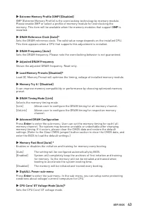
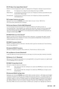
43 UEFI BIOS ▶ Extreme Memory Profile (XMP) [Disabled] XMP (Extreme Memory Profile) is the overclocking technology by memory module. Please enable XMP or select a profile of memory module for overclocking the memory. This item will be available when the memory modules that support XMP is installed. ...
Page 54 - ▶ CPU Specifications sub-menu; to enter the sub-menu. This sub-menu displays the information of
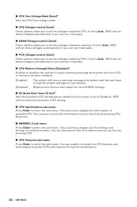
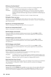
44 UEFI BIOS ▶ CPU Core Voltage Mode [Auto]* Sets the CPU Core voltage mode. ▶ CPU Voltages control [Auto] These options allow you to set the voltages related to CPU. If set to Auto , BIOS will set these voltages automatically or you can set it manually. ▶ DRAM Voltages control [Auto] These options ...
Page 55 - Inhalt; JTBT1: Anschluss für Thunderbolt-Erweiterungskarte
1 Inhalt Inhalt Sicherheitshinweis ................................................................................................ 3Spezifikationen ...................................................................................................... 4Packungsinhalt ...................................
Page 57 - Sicherheitshinweis
3 Sicherheitshinweis Sicherheitshinweis ∙ Die im Paket enthaltene Komponenten sind der Beschädigung durch elektrostatischen Entladung (ESD). Beachten Sie bitte die folgenden Hinweise, um die erfolgreichen Computermontage sicherzustellen. ∙ Stellen Sie sicher, dass alle Komponenten fest angeschlossen...
Page 58 - Spezifikationen; anschlüsse
4 Spezifikationen Spezifikationen CPU Unterstützt Intel® Core ™ der 10. Generation Prozessoren und Pentium® Gold / Celeron® Prozessoren für Sockel LGA 1200* * Weitere Kompatibilitätsinformationen finden Sie unter www.intel.com. * Die integrierte Grafikausgabe ist deaktiviert, wenn F-SKU-Prozessoren ...
Page 59 - Aufbewahrung; RAID
5 Spezifikationen Fortsetzung der vorherigen Seite Aufbewahrung Intel® Z490 Chipsatz ∙ 6x SATA 6Gb/s Anschlüsse* ∙ 2x M.2 Steckplätze (Key M) ▪ M2_1 unterstützt bis zu PCIe 3.0 x4 und SATA 6Gb/s, 2242/ 2260/ 2280/ 22110 Speichergeräte* ▪ M2_2 unterstützt bis zu PCIe 3.0 x4 und SATA 6Gb/s, 2242/ 2260...
Page 60 - Ausgänge; LED Funktionen
6 Spezifikationen Fortsetzung der vorherigen Seite Hintere Ein-/ und Ausgänge ∙ 1x PS/2 Tastatur/ Maus-Combo-Anschluss ∙ 2x USB 2.0 Anschlüsse ∙ 1x HDMI Anschluss ∙ 1x DisplayPort Anschluss ∙ 1x USB 3.2 Gen 2 10Gbit/s Typ-A Anschluss ∙ 1x USB 3.2 Gen 2 10Gbit/s Typ-C Anschluss ∙ 1x LAN(RJ45) Anschlu...
Page 62 - Besondere; Multi GPU-CrossFire Technologie
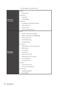
8 Spezifikationen Fortsetzung der vorherigen Seite Besondere Funktionen ∙ Audio ▪ Audio Boost ∙ Netzwerk ▪ 2,5G LAN ▪ LAN Manager ∙ Kühlung ▪ Verlängerter Kühlkörper Design ▪ M.2 Shield Frozr ▪ Pump- Lüfter ▪ Smart Lüftersteuerung Besondere Funktionen ∙ LED ▪ Mystic Light Extension(RGB) ▪ Mystic Lig...
Page 63 - Packungsinhalt; Notifizierung für Gehäuse-abstandshalter; Anwendung; Produktregistrierungskarte; Wichtig; bitte an Ihren Händler.
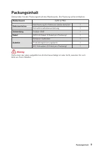
9 Packungsinhalt Packungsinhalt Überprüfen Sie den Packungsinhalt des Mainboards. Die Packung sollte enthalten: Motherboard Z490-A PRO Dokumentation Notifizierung für Gehäuse-abstandshalter 1 Schnellinstallationsanleitung 1 Anwendung Treiber-DVD 1 Kabel SATA 6G Kabel (2 Kabel pro Packung) 1 Zubehör ...
Page 64 - Verbindung/ Aktivität LED; Geschwindigkeit LED; LAN Port LED Zustandstabelle; DisplayPort; Audioanschlüsse
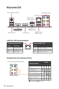
10 Rückseite E/A Rückseite E/A Verbindung/ Aktivität LED Zustand Bezeichnung Aus Keine Verbindung Gelb Verbindung Blinkt Datenaktivität Geschwindigkeit LED Zustand Aus 10 Mbit/s-Verbindung Grün 100 Mbit/s / 1 Gbit/s -Verbindung Orange 2,5 Gbit/s-Verbindung LAN Port LED Zustandstabelle Konfiguration ...
Page 65 - Geräteauswahl; - Ermöglicht die Auswahl der Audio-Ausgangs Quelle. Das aktuell; Optimierungen; - Die Vielfalt an Optionen bietet eine komplette Anleitung von; Lautstärke; die im Front-Panel oder auf der Rückseite des PCs eingesteckt sind.; - Konfiguriert die Anschlusseinstellungen.; erworbenen Produkt abweichen.
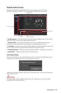
11 Rückseite E/A Realtek Audio Console Nach der Installation des Realtek Audio Console-Treibers, können Sie die Audioeinstellungen verändern, um ein optimales Klangerlebnis erzeugen. ∙ Geräteauswahl - Ermöglicht die Auswahl der Audio-Ausgangs Quelle. Das aktuell aktivierte Gerät ist mit einem Haken ...
Page 67 - Übersicht der Komponenten
13 Übersicht der Komponenten Übersicht der Komponenten DIMMA1 CPU_FAN1 DIMMA2 DIMMB1 DIMMB2 JRAINBOW1 PUMP_FAN1SYS_FAN6 SYS_FAN5 SYS_FAN1 SYS_FAN4 JRTD3 JFP1 JTBT1 SATA6 SATA5 JTPM1 JUSB1 JT1 JUSB2 JFP2 JCOM1 LED_SW1 JRAINBOW2 ATX_PWR1 JUSB4 JUSB5 JUSB3 CPU Sockel CPU_PWR1 CPU_PWR2 SATA▼1▲2 SATA▼3▲4...
Page 68 - Ziehen Sie das Netzkabel ab, bevor Sie die CPU ein- und ausbauen.; CPU Sockel; Justierungen
14 Übersicht der Komponenten ⚠ Wichtig ∙ Ziehen Sie das Netzkabel ab, bevor Sie die CPU ein- und ausbauen. ∙ Bitte bewahren Sie die CPU Schutzkappe nach der Installation des Prozessors auf. MSI wird RMA (Return Merchandise Authorization) Anfragen nur dann behandeln, wenn die Schutzklappe auf dem CPU...
Page 69 - Speichermodul-Installationsempfehlung; Stellen Sie im BIOS-Setup mit; die Speicherfrequenz ein, wenn Sie
15 Übersicht der Komponenten DIMM-Steckplätze DIMMA1 DIMMB1 Kanal A Kanal B DIMMA2 DIMMB2 Speichermodul-Installationsempfehlung ⚠ Wichtig ∙ Um einen sicheren Systemstart zu gewährleisten, bestücken Sie immer DIMMA2 zuerst. ∙ Stellen Sie im Dual-Kanal-Modus bitte sicher, dass Sie Module des gleichen ...
Page 70 - der das Gewicht trägt und eine
16 Übersicht der Komponenten PCI_E1~5: PCIe Erweiterungssteckplätze ⚠ Wichtig ∙ Wenn Sie eine große und schwere Grafikkarte einbauen, benötigen Sie einen Grafikkarten-Stabilisator (Graphics Card Bolster) der das Gewicht trägt und eine Verformung des Steckplatzes vermeidet. ∙ Für die Installation ein...
Page 72 - Abstandshalter
18 Übersicht der Komponenten 30º 30º 5 4 3 8,5H Schraube Abstandshalter 3. Wählen Sie die Montageposition entsprechend Ihrer M.2 SSD Länge. 4. Stecken Sie eine M.2-SSD im 30-Grad-Winkel in den M.2-Steckplatz . 5. Schrauben Sie den M.2 SSD mit 8,5H M.2-Schraube. 6. Setzen Sie den M.2 SHIELD FROZR-Küh...
Page 73 - Steckplatz
19 Übersicht der Komponenten SATA1~6: SATA 6Gb/s Anschlüsse Dieser Anschluss basiert auf der Hochgeschwindigkeitsschnittstelle SATA 6 Gb/s. Pro Anschluss kann ein SATA Gerät angeschlossen werden. ⚠ Wichtig ∙ Knicken Sie das SATA-Kabel nicht in einem 90° Winkel. Datenverlust könnte die Folge sein. ∙ ...
Page 74 - JCOM1: Serieller Anschluss
20 Übersicht der Komponenten JFP1, JFP2: Frontpanel-Anschlüsse Diese Anschlüsse verbinden die Schalter und LEDs des Frontpanels. 1 2 10 9 + + + - - - - + Power LED HDD LED Reset Switch Reserved Power Switch JFP1 1 HDD LED + 2 Power LED + 3 HDD LED - 4 Power LED - 5 Reset Switch 6 Power Switch 7 Rese...
Page 75 - Mit diesen Anschlüssen verbinden Sie die ATX Stromstecker.
21 Übersicht der Komponenten 24 13 1 12 ATX_PWR1 1 +3.3V 13 +3.3V 2 +3.3V 14 -12V 3 Ground 15 Ground 4 +5V 16 PS-ON# 5 Ground 17 Ground 6 +5V 18 Ground 7 Ground 19 Ground 8 PWR OK 20 Res 9 5VSB 21 +5V 10 +12V 22 +5V 11 +12V 23 +5V 12 +3.3V 24 Ground 5 4 1 8 CPU_PWR1 1 Ground 5 +12V 2 Ground 6 +12V 3...
Page 76 - JAUD1: Audioanschluss des Frontpanels; Anschluss auf dem
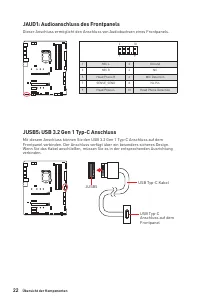
22 Übersicht der Komponenten JAUD1: Audioanschluss des Frontpanels Dieser Anschluss ermöglicht den Anschluss von Audiobuchsen eines Frontpanels. 1 2 10 9 1 MIC L 2 Ground 3 MIC R 4 NC 5 Head Phone R 6 MIC Detection 7 SENSE_SEND 8 No Pin 9 Head Phone L 10 Head Phone Detection JUSB5: USB 3.2 Gen 1 Typ...
Page 77 - Frontpanel verbinden.
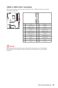
23 Übersicht der Komponenten JUSB3~4: USB 3.2 Gen 1 Anschlüsse Mit diesen Anschlüssen können Sie die USB 3.2 Gen 1 5Gbit/s Anschlüsse auf dem Frontpanel verbinden. ⚠ Wichtig Bitte beachten Sie, dass Sie die mit „Stromführende Leitung“ und „Erdleitung“ bezeichneten Pins korrekt verbinden müssen, anso...
Page 78 - Sie bitte die MSI
24 Übersicht der Komponenten JUSB1~2: USB 2.0 Anschlüsse Mit diesen Anschlüssen können Sie die USB 2.0 Anschlüsse auf dem Frontpanel verbinden. 1 2 10 9 1 VCC 2 VCC 3 USB0- 4 USB1- 5 USB0+ 6 USB1+ 7 Ground 8 Ground 9 No Pin 10 NC ⚠ Wichtig ∙ Bitte beachten Sie, dass Sie die mit VCC (Stromführende Le...
Page 79 - Lüfter; oder Spannungsmodus betrieben werden. Im PWM-Modus bieten die; Umschalten des Lüfter-Modus und Anpassung der Lüfterdrehzahl; BIOS > HARDWARE MONITOR; Anpasssung der Lüfterdrehzahl in Abhängigkeit von der CPU-; Pin-Belegung der Lüfteranschlüsse
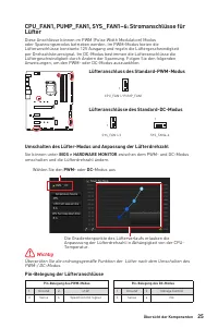
25 Übersicht der Komponenten CPU_FAN1, PUMP_FAN1, SYS_FAN1~6: Stromanschlüsse für Lüfter Diese Anschlüsse können im PWM (Pulse Width Modulation) Modus oder Spannungsmodus betrieben werden. Im PWM-Modus bieten die Lüfteranschlüsse konstante 12V Ausgang und regeln die Lüftergeschwindigkeit per Drehzah...
Page 80 - JCI1: Gehäusekontaktanschluss; Gehäusekontakt-Detektor verwenden
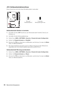
26 Übersicht der Komponenten JCI1: Gehäusekontaktanschluss Dieser Anschluss wird mit einem Kontaktschalter verbunden. Normal (Standardwert) Löse den Gehäuseeingriff aus Gehäusekontakt-Detektor verwenden 1. Schließen Sie den JCI1 -Anschluss am Gehäusekontakt-Schalter/ Sensor am Gehäuse an. 2. Schließ...
Page 81 - Mit diesem Anschluss können Sie eine Ein-/Ausgang der Thunderbolt-; JRTD3: Intel RTD3 Anschluss; A-Zusatzkarte anschließen mit RTD3-Unterstützung anschließen.
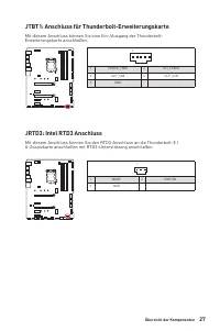
27 Übersicht der Komponenten JTBT1: Anschluss für Thunderbolt-Erweiterungskarte Mit diesem Anschluss können Sie eine Ein-/Ausgang der Thunderbolt- Erweiterungskarte anschließen. JRTD3: Intel RTD3 Anschluss Mit diesem Anschluss können Sie den RTD3-Anschluss an die Thunderbolt-E / A-Zusatzkarte anschl...
Page 82 - Rücksetzen des BIOS auf Standardwerte
28 Übersicht der Komponenten JBAT1: Clear CMOS Steckbrücke (Reset BIOS) Der Onboard CMOS Speicher (RAM) wird durch eine externe Spannungsversorgung durch eine Batterie auf dem Motherboard versorgt, um die Daten der Systemkonfiguration zu speichern. Wenn Sie die Systemkonfiguration löschen wollen, mü...
Page 83 - JRGB1: RGB LED Anschluss
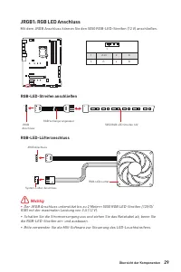
29 Übersicht der Komponenten ⚠ Wichtig ∙ Der JRGB Anschluss unterstützt bis zu 2 Metern 5050 RGB LED-Streifen (12V/G/ R/B) mit der maximalen Leistung von 3 A (12 V). ∙ Schalten Sie die Stromversorgung aus und ziehen Sie das Netzkabel ab, bevor Sie die RGB-LED-Streifen ein- und ausbauen. ∙ Bitte verw...
Page 84 - ACHTUNG; JRAINBOW1~2: Adressierbare RGB LED Anschlüsse; Adressierbarer RGB-LED-Streifen anschließen
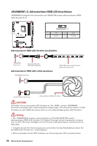
30 Übersicht der Komponenten 1 1 1 D +5V ⚠ ACHTUNG Schließen Sie nur passende LED-Streifen an. Der JRGB- und der JRAINBOW- Anschluss verfügen über unterschiedliche Spannungen. Der Anschluss eines 5 V LED- Streifens an den JRGB-Anschluss führt zu einer Beschädigung des LED-Streifens. ⚠ Wichtig ∙ Der ...
Page 85 - Diese LEDs zeigen d; - CPU wird nicht erkannt oder ist fehlerhaft.; - DRAM wird nicht erkannt oder ist fehlerhaft.; - GPU wird nicht erkannt oder ist fehlerhaft.; - Boot-Gerät wird nicht erkannt oder ist
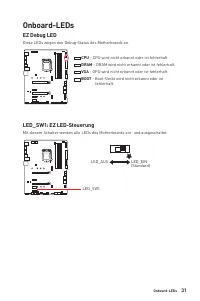
31 Onboard-LEDs EZ Debug LED Diese LEDs zeigen d en Debug-Status des Mo therboards an. CPU - CPU wird nicht erkannt oder ist fehlerhaft. DRAM - DRAM wird nicht erkannt oder ist fehlerhaft. VGA - GPU wird nicht erkannt oder ist fehlerhaft. BOOT - Boot-Gerät wird nicht erkannt oder ist fehlerhaft. Onb...
Page 86 - Installation von OS, Treibern und Utilities; Installation von Windows; 0 Disk oder das USB-Flashlaufwerk in das optisches; Installation von Treibern; im Hauptverzeichnis der MSI USB-Laufwerke; Installation von Utilities
32 Installation von OS, Treibern und Utilities Installation von OS, Treibern und Utilities Laden Sie die neuesten Treiber und Dienstprogramme von www.msi.com herunter und aktualisieren Sie sie Installation von Windows ® 10 1. Schalten Sie den Computer ein. 2. Legen Sie die Windows ® 10 Disk oder das...
Page 87 - Ältere Grafikkarten -
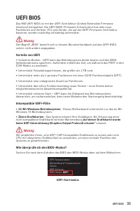
33 UEFI BIOS UEFI BIOS Das MSI UEFI-BIOS ist mit der UEFI-Architektur (Unified Extensible Firmware Interface) kompatibel. Die UEFI-BIOS-Firmware-Infrastruktur hat viele neue Funktionen und Vorteile. PCs und Geräte, die auf der UEFI-Firmware-Architektur basieren, werden zukünftig vollständig unterstü...
Page 88 - Öffnen des BIOS Setups; Funktionstasten
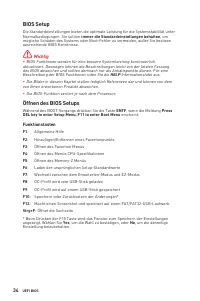
34 UEFI BIOS BIOS Setup Die Standardeinstellungen bieten die optimale Leistung für die Systemstabilität unter Normalbedingungen. Sie sollten immer die Standardeinstellungen behalten , um mögliche Schäden des Systems oder Boot-Fehler zu vermeiden, außer Sie besitzen ausreichende BIOS Kenntnisse. ⚠ Wi...
Page 89 - Reset des BIOS; Clear CMOS Steckbrücke; Bitte lesen Sie für Informationen zum BIOS-Reset im Bereich; „Clear CMOS; Aktualisierung des BIOS; Aktualisierung des BIOS mit dem M-FLASH-Programm; Beim Neustart drücken Sie während des POST-Vorgangs die Taste
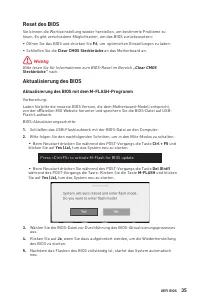
35 UEFI BIOS Reset des BIOS Sie können die Werkseinstellung wieder herstellen, um bestimmte Probleme zu lösen. Es gibt verschiedene Möglichkeiten, um das BIOS zurückzusetzen: ∙ Öffnen Sie das BIOS und drücken Sie F6 , um optimierten Einstellungen zu laden. ∙ Schließen Sie die Clear CMOS Steckbrücke ...
Page 90 - Aktualisierung des BIOS mit MSI DRAGON CENTER; Wählen Sie die BIOS-Datei aus und klicken Sie auf das
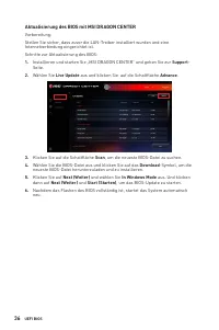
36 UEFI BIOS Aktualisierung des BIOS mit MSI DRAGON CENTER Vorbereitung: Stellen Sie sicher, dass zuvor die LAN-Treiber installiert wurden und eine Internetverbindung eingerichtet ist. Schritte zur Aktualisierung des BIOS: 1. Installieren und starten Sie „MSI DRAGON CENTER“ und gehen Sie zur Support...
Page 91 - EZ Modus; Drücken des; - Mit dieser Option können Sie das XMP-Profil auswählen, dessen
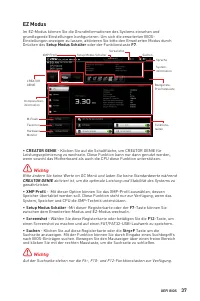
37 UEFI BIOS EZ Modus Im EZ-Modus können Sie die Grundinformationen des Systems einsehen und grundlegende Einstellungen konfigurieren. Um sich die erweiterten BIOS- Einstellungen anzeigen zu lassen, aktivieren Sie bitte den Erweiterten Modus durch Drücken des Setup Modus Schalter oder der Funktionst...
Page 93 - Um ein BIOS-Punkte zu einer Favoritenmenü hinzufügen; Klicken Sie mit der rechten Maustaste oder drücken Sie die Taste; Um ein BIOS-Punkte von Favoritenmenü zu löschen; Wählen Sie einen BIOS-Eintrag auf einer Favoritenmenü.; aus und klicken Sie auf
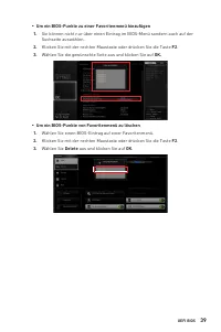
39 UEFI BIOS ▪ Um ein BIOS-Punkte zu einer Favoritenmenü hinzufügen 1. Sie können nicht nur über einen Eintrag im BIOS-Menü sondern auch auf der Suchseite auswählen. 2. Klicken Sie mit der rechten Maustaste oder drücken Sie die Taste F2 . 3. Wählen Sie die gewünschte Seite aus und klicken Sie auf OK...
Page 94 - Erweiterter Modus; Drücken Sie den; - Die folgenden Optionen stehen zur Verfügung.
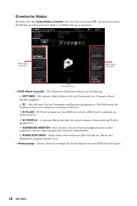
40 UEFI BIOS Erweiterter Modus Drücken Sie den Setup Modus Schalter oder die Funkionstaste F7 , um zwischen dem EZ-Modus und Erweiterten-Modus im BIOS-Setup zu wechseln. BIOS-Menü -Auswahl Menüanzeige BIOS-Menü -Auswahl ∙ BIOS-Menü-Auswahl - Die folgenden Optionen stehen zur Verfügung. ▪ SETTINGS - ...
Page 95 - OC Menü; Bietet normale Übertaktungseinstellungen im BIOS-Setup.
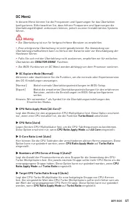
41 UEFI BIOS OC Menü In diesem Menü können Sie die Frequenzen und Spannungen für das Übertakten konfigurieren. Bitte beachten Sie, dass höhere Frequenzen und Spannungen die Übertaktungsfähigkeit verbessern können, jedoch zu einer Instabilität des Systems führen. ⚠ Wichtig ∙ Die Übertaktung ist nur f...
Page 96 - Änderungen sind nicht möglich.
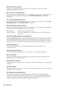
42 UEFI BIOS ▶ Adjusted CPU Frequency Zeigt die eingestellte Frequenz der CPU an. Es handelt sich um eine Anzeige – Änderungen sind nicht möglich. ▶ Core X X of X xxxx MHz [Auto] Hier können Sie die CPU Taktraten der verschiedenen aktiven Kerne anpassen. Diese Optionen kann nur geändert werden, wenn...
Page 97 - Clockgen Features sub-menu
43 UEFI BIOS ▶ CPU Base Clock Apply Mode [Auto]* Einstellung des angepassten CPU Grundtakts.[Auto] Diese Einstellungen werden vom BIOS automatisch konfiguriert. [Next Boot] Die CPU arbeitet mit angepasstem CPU Grundtakt nach einem Neustart. [Immediate] Die CPU arbeitet mit angepasstem CPU Grundtakt ...
Page 98 - Deaktivierung der Funktion und Beibehaltung der aktuellen BIOS-; Deaktiviert; gesetzt ist, wird das BIOS die unterschiedlichen OC-
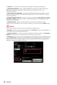
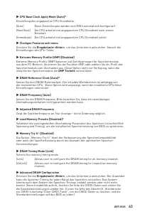
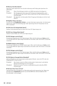
44 UEFI BIOS ▶ Memory Fast Boot [Auto] * Aktivieren oder deaktivieren Sie die die Initiierung und Prüfung des Speichers für jeden Boot. [Auto] Diese Einstellungen werden vom BIOS automatisch konfiguriert. [Enabled] Der Vorgang der Initierung und Prüfung des Hauptspeichers wird aus dem Archiv der ers...
Page 99 - CPU Features sub-menu; Drücken Sie die
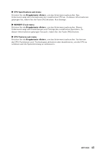
45 UEFI BIOS ▶ CPU Specifications sub-menu Drücken Sie die Eingabetaste <Enter> , um das Untermenü aufzurufen. Das Untermenü zeigt die Informationen der installierten CPU an. Zu diesen Informationen gelangen Sie, indem Sie die Taste [F4] drücken. Nur Anzeige. ▶ MEMORY-Z sub-menu Drücken Sie di...
Page 101 - Table des matières
1 Table des matières Table des matières Informations de sécurité ....................................................................................... 3Spécifications ......................................................................................................... 4Contenu ...................
Page 103 - Informations de sécurité; veuillez vous référer aux instructions ci-dessous.
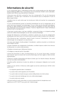
3 Informations de sécurité Informations de sécurité ∙ Les composants dans l’emballage peuvent être endommagés par des décharges électrostatiques (ESD). Pour vous assurer de correctement monter votre ordinateur, veuillez vous référer aux instructions ci-dessous. ∙ Assurez-vous de bien connecter tous ...
Page 104 - Spécifications; Support de la technologie AMD® CrossFireTM 2-Way
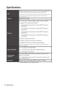
4 Spécifications Spécifications CPU Support des processeurs Intel® Core™ de 10ème génération et Pentium® Gold / Celeron® pour socket LGA 1200* * Veuillez vous au site www.intel.com pour plus d’informations de compatibilité.* Les sorties vidéo intégrées sont indisponibles lors de l’utilisation des pr...
Page 105 - Stockage
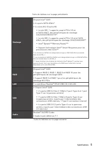
5 Spécifications Suite du tableau sur la page précédente Stockage Chipset Intel® Z490 ∙ 6 x ports SATA 6Gb/s* ∙ 2 x slots M.2 (Touche M) ▪ Le slot M2_1 supporte jusqu’à PCIe 3.0 x4 et SATA 6Gb/s, des périphériques de stockage 2242/2260/2280/22110* ▪ Le slot M2_2 supporte jusqu’à PCIe 3.0 x4 et SATA ...
Page 106 - Connecteurs sur le; Fonctions LED
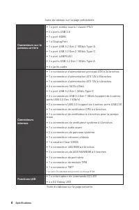
6 Spécifications Suite du tableau sur la page précédente Connecteurs sur le panneau arrière ∙ 1 x port combo souris / clavier PS/2 ∙ 2 x ports USB 2.0 ∙ 1 x port HDMI ∙ 1 x DisplayPort ∙ 1 x port USB 3.2 Gen 2 10Gb/s Type-A ∙ 1 x port USB 3.2 Gen 2 10Gb/s Type-C ∙ 1 x port LAN(RJ45) ∙ 2 x ports USB ...
Page 108 - Fonctions spéciales; Technologie Multi GPU-CrossFire
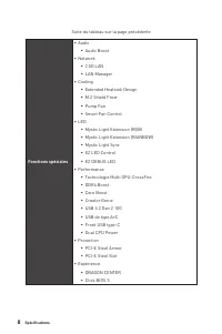
8 Spécifications Suite du tableau sur la page précédente Fonctions spéciales ∙ Audio ▪ Audio Boost ∙ Network ▪ 2.5G LAN ▪ LAN Manager ∙ Cooling ▪ Extended Heatsink Design ▪ M.2 Shield Frozr ▪ Pump Fan ▪ Smart Fan Control ∙ LED ▪ Mystic Light Extension (RGB) ▪ Mystic Light Extension (RAINBOW) ▪ Mysti...
Page 109 - Contenu; Carte mère
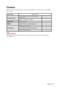
9 Contenu Contenu Vérifiez tous les articles dans le carton d'emballage de votre carte mère. L'emballage doit contenir : Carte mère Z490-A PRO Documentation Avertissement pour l’installation des entretoises 1 Guide d’installation rapide 1 Application DVD de pilotes 1 Câbles Câble SATA 6G (2 câbles/p...
Page 110 - Panneau arrière Entrée / Sortie; LED indiquant la connexion; Tableau explicatif de l’état de la LED du port LAN; Ports Audio; Espace
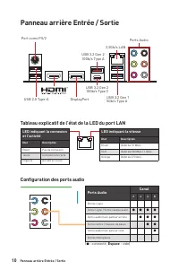
10 Panneau arrière Entrée / Sortie Panneau arrière Entrée / Sortie Port como PS/2 2,5Gb/s LAN USB 2.0 Type-A DisplayPort Ports Audio USB 3.2 Gen 2 10Gb/s Type A USB 3.2 Gen 1 5Gb/s Type A USB 3.2 Gen 2 10Gb/s Type C LED indiquant la connexion et l’activité Etat Description Eteint Pas de connexion Ja...
Page 111 - paramètres du son afin d’obtenir une meilleure expérience sonore.; Sélection du périphérique; - vous permet de sélectionner une source de sortie; Amélioration d’application; - les diverses options vous fournissent un guide complet; Volume principal; - contrôle le volume ou équilibre le son gauche / droite des haut-; Etat des prises Jack; - présente tous les périphériques de diffusion et de capture; Paramètres du connecteur; - configure les paramètres de connexion.; le produit que vous achetez.
11 Panneau arrière Entrée / Sortie Realtek Audio Console Après l’installation de Realtek Audio Console, vous pouvez l’utiliser pour modifier les paramètres du son afin d’obtenir une meilleure expérience sonore. ∙ Sélection du périphérique - vous permet de sélectionner une source de sortie audio pour...
Page 112 - microphone
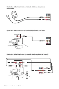
12 Panneau arrière Entrée / Sortie AUDIO INPUT Rear Front Side Center/ Subwoofer AUDIO INPUT Illustration de l’utilisation des ports audio dédiés au casque et au microphone Illustration de l’utilisation du port audio dédié aux haut-parleurs Illustration de l’utilisation des ports audio dédiés aux ha...
Page 113 - Vue d’ensemble des composants
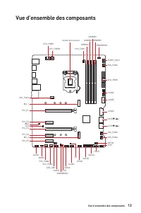
13 Vue d’ensemble des composants Vue d’ensemble des composants DIMMA1 CPU_FAN1 DIMMA2 DIMMB1 DIMMB2 JRAINBOW1 PUMP_FAN1SYS_FAN6 SYS_FAN5 SYS_FAN1 SYS_FAN4 JRTD3 JFP1 JTBT1 SATA6 SATA5 JTPM1 JUSB1 JT1 JUSB2 JFP2 JCOM1 LED_SW1 JRAINBOW2 ATX_PWR1 JUSB4 JUSB5 JUSB3 Socket processeur CPU_PWR1 CPU_PWR2 SA...
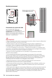
Page 114 - Socket processeur; Présentation du socket LGA 1200; encoches
14 Vue d’ensemble des composants ⚠ Important ∙ Avant d’installer ou de retirer le processeur du socket, veillez à toujours débrancher le câble d’alimentation de la prise électrique. ∙ Veuillez garder le capot de protection du processeur après l’installation du processeur. Selon les exigences de RMA ...
Page 115 - Slots DIMM; Installation recommandée de module mémoire; en; pour régler la fréquence de mémoire si vous voulez faire
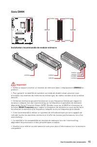
15 Vue d’ensemble des composants Slots DIMM DIMMA1 DIMMB1 Canal A Canal B DIMMA2 DIMMB2 Installation recommandée de module mémoire ⚠ Important ∙ Veillez à toujours insérer un module de mémoire dans l’emplacement DIMMA2 en premier. ∙ Pour garantir la stabilité du système au mode de double canal, assu...
Page 116 - la; barre de support MSI Gaming Series; pour supporter son poids et pour éviter la
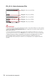
16 Vue d’ensemble des composants PCI_E1~5 : Slots d’extension PCIe ⚠ Important ∙ Si vous installez une carte graphique lourde, il vous faut utiliser un outil comme la barre de support MSI Gaming Series pour supporter son poids et pour éviter la déformation du slot. ∙ Si vous choisissez d’installer u...
Page 117 - Intel® OptaneTM Memory Ready pour le slot M.2.; Vidéo de démonstration; Référez-vous à la vidéo d’installation du; Installation du module M.2; Retirez la plaque M.2 SHIELD FROZR et
17 Vue d’ensemble des composants M2_1~2 : Slots M.2 (Touche M) M2_1 M2_2 ⚠ Important ∙ La technologie Intel® RST supporte seulement un SSD M.2 PCIe avec une mémoire ROM UEFI. ∙ Intel® Optane™ Memory Ready pour le slot M.2. ⚽ Vidéo de démonstration Référez-vous à la vidéo d’installation du module M.2...
Page 118 - Entretoise
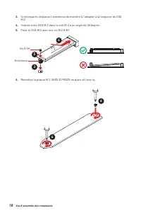
18 Vue d’ensemble des composants 30º 30º 5 4 3 Vis 8.5H Entretoise 3. Si nécessaire, déplacez l’entretoise de manière à l’adapter à la longueur du SSD M.2. 4. Insérez votre SSD M.2 dans le slot M.2 à un angle de 30 degrés. 5. Fixez le SSD M.2 avec une vis M.2 8.5H. 6. Remettez la plaque M.2 SHIELD F...
Page 120 - JFP1, JFP2 : Connecteurs de panneau avant
20 Vue d’ensemble des composants JFP1, JFP2 : Connecteurs de panneau avant Ces connecteurs se lient aux interrupteurs et indicateurs LED du panneau avant. 1 2 10 9 + + + - - - - + Power LED HDD LED Reset Switch Reserved Power Switch JFP1 1 HDD LED + 2 Power LED + 3 HDD LED - 4 Power LED - 5 Reset Sw...
Page 121 - Ces connecteurs vous permettent de relier une alimentation ATX.
21 Vue d’ensemble des composants 24 13 1 12 ATX_PWR1 1 +3.3V 13 +3.3V 2 +3.3V 14 -12V 3 Ground 15 Ground 4 +5V 16 PS-ON# 5 Ground 17 Ground 6 +5V 18 Ground 7 Ground 19 Ground 8 PWR OK 20 Res 9 5VSB 21 +5V 10 +12V 22 +5V 11 +12V 23 +5V 12 +3.3V 24 Ground 5 4 1 8 CPU_PWR1 1 Ground 5 +12V 2 Ground 6 +1...
Page 122 - JAUD1 : Connecteur audio avant; Ce connecteur se lie aux jacks audio du panneau avant.
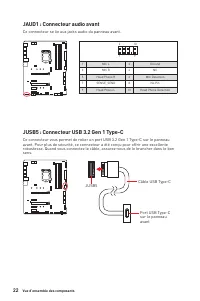
22 Vue d’ensemble des composants JAUD1 : Connecteur audio avant Ce connecteur se lie aux jacks audio du panneau avant. 1 2 10 9 1 MIC L 2 Ground 3 MIC R 4 NC 5 Head Phone R 6 MIC Detection 7 SENSE_SEND 8 No Pin 9 Head Phone L 10 Head Phone Detection JUSB5 : Connecteur USB 3.2 Gen 1 Type-C Ce connect...
Page 123 - afin d’éviter d’endommager la carte.
23 Vue d’ensemble des composants JUSB3~4 : Connecteurs USB 3.2 Gen 1 Ces connecteurs vous permettent de relier des ports USB 3.2 Gen 1 5Gb/s sur le panneau avant. ⚠ Important Notez que les câbles d’alimentation et de terre doivent être branchés correctement afin d’éviter d’endommager la carte. 1 10 ...
Page 124 - d’éviter tout dommage sur la carte mère.; JTPM1 : Connecteur de module TPM; référer au manuel du module TPM pour plus d’informations.
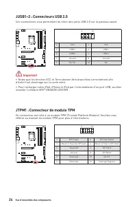
24 Vue d’ensemble des composants JUSB1~2 : Connecteurs USB 2.0 Ces connecteurs vous permettent de relier des ports USB 2.0 sur le panneau avant. 1 2 10 9 1 VCC 2 VCC 3 USB0- 4 USB1- 5 USB0+ 6 USB1+ 7 Ground 8 Ground 9 No Pin 10 NC ⚠ Important ∙ Notez que les broches VCC et Terre doivent être branché...
Page 125 - ventilateurs
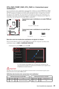
25 Vue d’ensemble des composants CPU_FAN1, PUMP_FAN1, SYS_FAN1~6 : Connecteurs pour ventilateurs Les connecteurs pour ventilateurs peuvent être utilisés en mode PWM (Pulse Width Modulation) et en mode DC. En mode PWM, les connecteurs fournissent une sortie de 12V constante et ajustent la vitesse des...
Page 126 - JCI1 : Connecteur intrusion châssis; Utilisation du détecteur d’intrusion châssis; Réinitialisation de l’alerte intrusion châssis; Intrusion Configuration (Configuration intrusion châssis)
26 Vue d’ensemble des composants JCI1 : Connecteur intrusion châssis Ce connecteur est relié à un câble d’interrupteur intrusion châssis. Normal (défaut) Commencer l’activité instrusion châssis Utilisation du détecteur d’intrusion châssis 1. Reliez le connecteur JCI1 à l’interrupteur ou au capteur d...
Page 127 - JTBT1 : Connecteur de carte additionnelle Thunderbolt
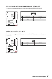
27 Vue d’ensemble des composants JTBT1 : Connecteur de carte additionnelle Thunderbolt Ce connecteur vous permet de relier une carte additionnelle Thunderbolt E/S. JRTD3 : Connecteur Intel RTD3 Ce connecteur vous permet de brancher le connecteur RTD3 sur la carte additionnelle Thunderbolt. 1 1 FORCE...
Page 128 - manière à nettoyer la mémoire CMOS.; Réinitialiser le BIOS aux valeurs par défaut; Utilisez un couvercle de cavalier pour fermer
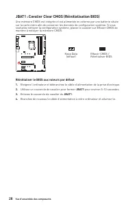
28 Vue d’ensemble des composants JBAT1 : Cavalier Clear CMOS (Réinitialisation BIOS) Une mémoire CMOS est intégrée et est alimentée en externe par une batterie située sur la carte mère afin de conserver les données de configuration système. Si vous souhaitez nettoyer la configuration système, placez...
Page 129 - JRGB1 : Connecteur LED RGB; Connexion du ruban LED RGB
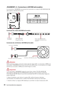
29 Vue d’ensemble des composants ⚠ Important ∙ Le connecteur JRGB supporte des rubans LED RGB (12V/G/R/B) de type 5050 d’une longueur de 2 mètres maximum avec une puissance nominale maximale de 3A (12V). ∙ Avant d’installer ou de retirer le ruban LED RGB, veillez à toujours éteindre l’alimentation e...
Page 130 - Attention; LED 5V au connecteur JRGB peut endommager le ruban.; JRAINBOW1~2 : Connecteurs LED RGB adressables; adressables individuellement 5V.; Connexion du ruban LED RGB adressable
30 Vue d’ensemble des composants 1 1 1 D +5V ⚠ Attention Faites attention à bien connecter le bon type de ruban LED. Le connecteur JRGB et le connecteur JRAINBOW fournissent des tensions différentes. La connexion d’un ruban LED 5V au connecteur JRGB peut endommager le ruban. ⚠ Important ∙ Le connect...
Page 131 - Ces LEDs indiquent l’état de débogage de la carte mère.; Indicateurs LED embarqués; - indique que le CPU n’est pas détecté ou que; -indique que la mémoire DRAM n’est pas; - indique que le GPU n’est pas détecté ou que; - indique que le périphérique de démarrage
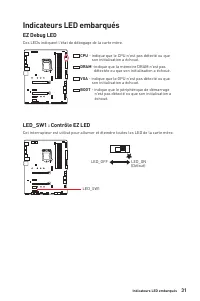
31 Indicateurs LED embarqués EZ Debug LED Ces LEDs indiquent l’état de débogage de la carte mère. Indicateurs LED embarqués LED_SW1 : Contrôle EZ LED Cet interrupteur est utilisé pour allumer et éteindre toutes les LED de la carte mère. LED_SW1 LED_OFF LED_ON (Défaut) CPU - indique que le CPU n’est ...
Page 132 - Installer OS, Pilotes et Utilitaires; Installer Windows® 10; Choisir quoi faire avec ce disque (Select to choose; Installer les utilitaires
32 Installer OS, Pilotes et Utilitaires Installer OS, Pilotes et Utilitaires Veuillez vous référer au site www.msi.com pour télécharger et mettre à jour les derniers utilitaires et pilotes. Installer Windows® 10 1. Allumez l’ordinateur. 2. Insérez le disque ou la clé USB d’installation de Windows® 1...
Page 133 - Système d’exploitation Windows 32 bits; - cette carte mère supporte uniquement le; Carte graphique ancienne; - le système détectera votre carte graphique. Un; aucun support GOP (Graphics Output Protocol); Mode de démarrage UEFI
33 UEFI BIOS UEFI BIOS Le BIOS UEFI de MSI est compatible avec l’architecture UEFI (Unified Extensible Firmware Interface). L’infrastructure du firmware du BIOS UEFI présente de nombreuses nouvelles fonctionnalités et avantages que le BIOS traditionnel ne peut pas atteindre. Il supportera complèteme...
Page 134 - Configuration du BIOS; toujours garder les réglages par défaut; Entrer dans l’interface Setup du BIOS; Press DEL key to enter Setup; Touches de fonction
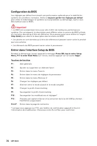
34 UEFI BIOS Configuration du BIOS Les réglages par défaut fournissent une performance optimale pour la stabilité du système en conditions normales. Veillez à toujours garder les réglages par défaut pour éviter d’endommager le système ou tout problème au démarrage, sauf si vous êtes familier avec le...
Page 135 - Réinitialiser le BIOS; Court-circuitez le cavalier; Clear CMOS; Mettre le BIOS à jour; Mettre le BIOS à jour avec M-FLASH; Del
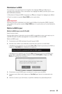
35 UEFI BIOS Réinitialiser le BIOS Il se peut que vous ayez besoin de récupérer les réglages BIOS par défaut pour résoudre des problèmes. Pour réinitialiser les réglages du BIOS, veuillez suivre l’une des méthodes suivantes : ∙ Allez dans le Setup du BIOS et appuyez sur F6 pour charger les réglages ...
Page 136 - Mettre le BIOS à jour avec MSI DRAGON CENTER; Support
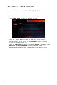
36 UEFI BIOS Mettre le BIOS à jour avec MSI DRAGON CENTER Avant la mise à jour : Assurez-vous que le lecteur LAN est bien installé et que l’ordinateur est correctement connecté à internet. Mettre le BIOS à jour : 1. Installez et lancez MSI DRAGON CENTER et accédez à la page Support . 2. Choisissez L...
Page 137 - - cliquez dessus pour basculer le CREATOR GENIE pour; - appuyez sur ce menu ou la touche
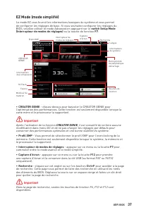
37 UEFI BIOS EZ Mode (mode simplifié) Le mode EZ vous fournit les informations basiques du système et vous permet de configurer les réglages de base. Si vous souhaitez configurer les réglages du BIOS, veuillez utiliser le mode Advanced en appuyant sur le switch Setup Mode (Interrupteur de modes de r...
Page 139 - Ajouter un élément du BIOS au menu Favoris
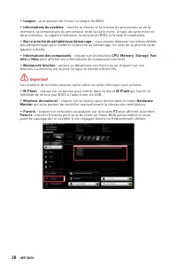
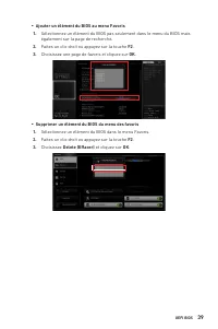
39 UEFI BIOS ▪ Ajouter un élément du BIOS au menu Favoris 1. Sélectionnez un élément du BIOS pas seulement dans le menu du BIOS mais également sur la page de recherche. 2. Faites un clic droit ou appuyez sur la touche F2 . 3. Choisissez une page de favoris et cliquez sur OK . ▪ Supprimer un élément ...
Page 143 - pour entrer dans le sous-menu. Définit les; pour entrer dans le sous-menu. L’utilisateur peut régler
43 UEFI BIOS ▶ CPU Base Clock Apply Mode [Auto]* Définit le mode d’application pour le réglage de la fréquence de base du processeur. [Auto] Ce réglage est configuré automatiquement par le BIOS. [Next Boot] Le processeur fonctionne avec une fréquence de base paramétrée pour le prochain démarrage. [I...
Page 145 - Entrée; Entrée; pour entrer dans le sous-men
45 UEFI BIOS ▶ MEMORY-Z sub-menu Appuyez sur la touche Entrée pour accéder au sous-menu. Ce sous-menu affiche tous les réglages et timings de la mémoire installée. Vous pouvez également accéder à ce sous-menu à tout moment en appuyant sur la touche [F5]. ▶ CPU Features sub-menu Appuyez sur la touche...
Page 147 - Содержание
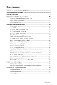
1 Содержание Содержание Безопасное использование продукции ............................................................. 3 Технические характеристики ............................................................................. 4 Комплект поставки .......................................................
Page 149 - Безопасное использование продукции
3 Безопасное использование продукции Безопасное использование продукции ∙ Компоненты, входящие в комплект поставки могут быть повреждены статическим электричеством. Для успешной сборки компьютера, пожалуйста, следуйте указаниям ниже. ∙ Убедитесь, что все компоненты компьютера подключены должным обра...
Page 150 - Технические характеристики; GPU
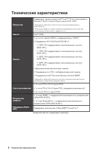
4 Технические характеристики Технические характеристики Процессор Поддержка процессоров Intel® Core™ 10-ого поколения и Pentium® Gold / Celeron®для сокета LGA 1200* * Пожалуйста, обратитесь intel.com для получения информации о совместимости.* Встроенная графика не будет выводить изображение на монит...
Page 151 - Подключение; Realtek® ALC892 Codec
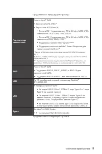
5 Технические характеристики Продолжение с предыдущей страницы Подключение накопителей Чипсет Intel® Z490 ∙ 6x портов SATA 6Гб/с* ∙ 2x разъема M.2 (Ключ M) ▪ Разъем M2_1 поддерживает PCIe 3.0 x4 и SATA 6Гб/с, накопители 2242/ 2260/ 2280/ 22110* ▪ Разъем M2_2 поддерживает PCIe 3.0 x4 и SATA 6Гб/с, на...
Page 152 - Разъемы задней; Параметры
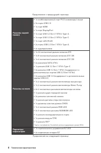
6 Технические характеристики Продолжение с предыдущей страницы Разъемы задней панели ∙ 1x комбинированный порт PS/2 клавиатуры/ мыши ∙ 2x порта USB 2.0 ∙ 1x порт HDMI ∙ 1x порт DisplayPort ∙ 1x порт USB 3.2 Gen 2 10Гб/с Type-A ∙ 1x порт USB 3.2 Gen 2 10Гб/с Type-C ∙ 1x порт LAN (RJ45) ∙ 2x порта USB...
Page 153 - Center
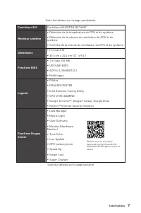
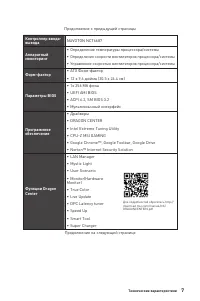
7 Технические характеристики Продолжение с предыдущей страницы Контроллер ввода- вывода NUVOTON NCT6687 Аппаратный мониторинг ∙ Определение температуры процессора/системы ∙ Определение скорости вентиляторов процессора/системы ∙ Управление скоростью вентиляторов процессора/системы Форм-фактор ∙ ATX Ф...
Page 154 - Эксклюзивные
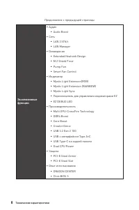
8 Технические характеристики Продолжение с предыдущей страницы Эксклюзивные функции ∙ Аудио ▪ Audio Boost ∙ Сеть ▪ LAN 2.5Гб/с ▪ LAN Manager ∙ Охлаждение ▪ Extended Heatsink Design ▪ M.2 Shield Frozr ▪ Pump Fan ▪ Smart Fan Control ∙ Индикатор ▪ Mystic Light Extension(RGB) ▪ Mystic Light Extension (R...
Page 155 - Комплект поставки; Материнская плата
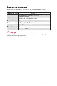
9 Комплект поставки Комплект поставки Проверьте комплект поставки материнской платы. В него должны входить следующие элементы: Материнская плата Z490-A PRO Документы Уведомление о стойках для крепления материнской платы 1 Руководство по быстрой установке 1 Диск с утилитами Диск с драйверами 1 Кабели...
Page 156 - Задняя панель портов ввода/ вывода; Комбинированный порт PS/2; индикатора; Таблица состояний индикатора порта LAN
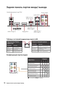
10 Задняя панель портов ввода/ вывода Задняя панель портов ввода/ вывода Комбинированный порт PS/2 LAN 2.5Гб/с USB 2.0 Type-A DisplayPort Порты Аудио USB 3.2 Gen 2 10Гб/с Type A USB 3.2 Gen 1 5Гб/с Type A USB 3.2 Gen 2 10Гб/с Type C Подключение/ Работа индикатора Состояние Описание Выкл. Не подключе...
Page 157 - ∙ Выбор устройства; Автоматическое всплывающее диалоговое окно
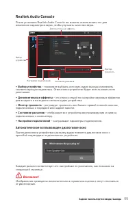
11 Задняя панель портов ввода/ вывода Realtek Audio Console После установки Realtek Audio Console вы можете использовать его для изменения параметров звука, чтобы улучшить качество звука. ∙ Выбор устройства – позволяет выбрать источник аудио выхода и изменить соответствующие параметры. Отмеченное ус...
Page 158 - Подключение наушников и микрофона
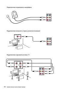
12 Задняя панель портов ввода/ вывода Подключение наушников и микрофона Подключение внешнего стерео усилителя (колонок) Подключение звуковой системы 7.1 AUDIO INPUT AUDIO INPUT Rear Front Side Center/ Subwoofer
Page 159 - Компоненты материнской платы
13 Компоненты материнской платы Компоненты материнской платы DIMMA1 CPU_FAN1 DIMMA2 DIMMB1 DIMMB2 JRAINBOW1 PUMP_FAN1SYS_FAN6 SYS_FAN5 SYS_FAN1 SYS_FAN4 JRTD3 JFP1 JTBT1 SATA6 SATA5 JTPM1 JUSB1 JT1 JUSB2 JFP2 JCOM1 LED_SW1 JRAINBOW2 ATX_PWR1 JUSB4 JUSB5 JUSB3 CPU_PWR1 CPU_PWR2 SATA▼1▲2 SATA▼3▲4 SYS_...
Page 160 - Процессорный сокет; выемки
14 Компоненты материнской платы ⚠ Внимание! ∙ Перед установкой или заменой процессора, необходимо отключить кабель питания. ∙ Пожалуйста, сохраните защитную крышку процессорного сокета после установки процессора. Любые возможные гарантийные случаи, связанные с работой материнской платы, MSI® будет р...
Page 161 - Слоты DIMM; Рекомендации по установке модулей памяти; Всегда устанавливайте модуль памяти сначала в слот; , чтобы установить заявленную или более
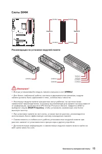
15 Компоненты материнской платы Слоты DIMM DIMMA1 DIMMB1 Канал A Канал B DIMMA2 DIMMB2 Рекомендации по установке модулей памяти ⚠ Внимание! ∙ Всегда устанавливайте модуль памяти сначала в слот DIMMA2 . ∙ Для более стабильной работы системы в двухканальном режимах, модули памяти должны быть одинаково...
Page 162 - MSI Gaming Series Graphics Card Bolster; для поддержки веса
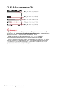
16 Компоненты материнской платы PCI_E1~5: Слоты расширения PCIe ⚠ Внимание! ∙ При установке массивной видеокарты, необходимо использовать такой инструмент, как MSI Gaming Series Graphics Card Bolster для поддержки веса графической карты и во избежание деформации слота. ∙ Для установки одной карты ра...
Page 163 - Технология Intel® RST только поддерживает PCIe M.2 SSD с UEFI ROM.; Видео Инструкция; Смотрите видео, чтобы узнать как
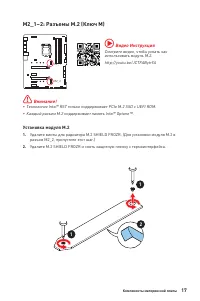
17 Компоненты материнской платы M2_1~2: Разъемы M.2 (Ключ M) M2_1 M2_2 ⚠ Внимание! ∙ Технология Intel® RST только поддерживает PCIe M.2 SSD с UEFI ROM. ∙ Каждый разъем M.2 поддерживает память Intel® Optane™. ⚽ Видео Инструкция Смотрите видео, чтобы узнать как использовать модуль M.2. http://youtu.be...
Page 164 - Стойка
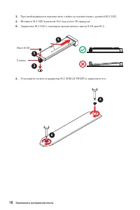
18 Компоненты материнской платы 30º 30º 5 4 3 Винт 8.5H Стойка 3. При необходимости переместите стойки в соответствии с длиной M.2 SSD. 4. Вставьте M.2 SSD в разъем М.2 под углом 30 градусов. 5. Закрепите M.2 SSD с помощью прилагаемого винта 8.5H для M.2. 6. Установите на место радиатор M.2 SHIELD F...
Page 165 - порту можно подключить одно устройство SATA.; Таблица комбинации для слотов M.2 и SATA; Слот
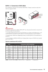
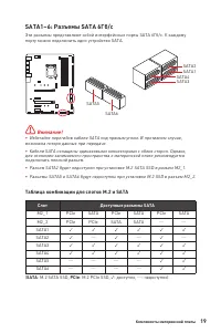
19 Компоненты материнской платы SATA1~6: Разъемы SATA 6Гб/с Эти разъемы представляют собой интерфейсные порты SATA 6Гб/с. К каждому порту можно подключить одно устройство SATA. ⚠ Внимание! ∙ Избегайте перегибов кабеля SATA под прямым углом. В противном случае, возможна потеря данных при передаче. ∙ ...
Page 166 - расположенных на передней панели.; JCOM1: Разъем последовательного порта
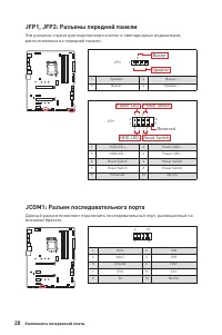
20 Компоненты материнской платы JFP1, JFP2: Разъемы передней панели Эти разъемы служат для подключения кнопок и светодиодных индикаторов, расположенных на передней панели. 1 2 10 9 + + + - - - - + Power LED HDD LED Reset Switch Reserved Power Switch JFP1 1 HDD LED + 2 Power LED + 3 HDD LED - 4 Power...
Page 167 - подключения всех кабелей питания к блоку питания АТХ.
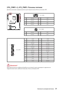
21 Компоненты материнской платы 24 13 1 12 ATX_PWR1 1 +3.3V 13 +3.3V 2 +3.3V 14 -12V 3 Ground 15 Ground 4 +5V 16 PS-ON# 5 Ground 17 Ground 6 +5V 18 Ground 7 Ground 19 Ground 8 PWR OK 20 Res 9 5VSB 21 +5V 10 +12V 22 +5V 11 +12V 23 +5V 12 +3.3V 24 Ground 5 4 1 8 CPU_PWR1 1 Ground 5 +12V 2 Ground 6 +12...
Page 168 - JAUD1: Разъем аудио передней панели; Данный разъем предназначен для подключения портов 3.2 Gen 1 Type-C
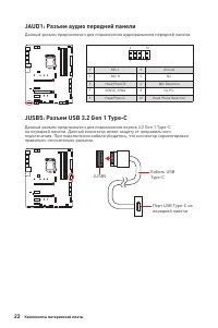
22 Компоненты материнской платы JAUD1: Разъем аудио передней панели Данный разъем предназначен для подключения аудиоразъемов передней панели. 1 2 10 9 1 MIC L 2 Ground 3 MIC R 4 NC 5 Head Phone R 6 MIC Detection 7 SENSE_SEND 8 No Pin 9 Head Phone L 10 Head Phone Detection JUSB5: Разъем USB 3.2 Gen 1...
Page 169 - контакты питания и земли.
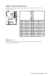
23 Компоненты материнской платы JUSB3~4: Разъемы USB 3.2 Gen 1 Данные разъемы предназначен для подключения портов USB 3.2 Gen 1 5Гб/с на передней панели. ⚠ Внимание! Помните, что во избежание повреждений, необходимо правильно подключать контакты питания и земли. 1 10 11 20 1 Power 11 USB2.0+ 2 USB3_...
Page 170 - контакты VCC и земли.; JTPM1: Разъем модуля ТРМ
24 Компоненты материнской платы JUSB1~2: Разъемы USB 2.0 Данные разъемы предназначены для подключения портов USB 2.0 на передней панели. 1 2 10 9 1 VCC 2 VCC 3 USB0- 4 USB1- 5 USB0+ 6 USB1+ 7 Ground 8 Ground 9 No Pin 10 NC ⚠ Внимание! ∙ Помните, что во избежание повреждений, необходимо правильно под...
Page 171 - Разъем с управлением постоянным током; Назначение контактов разъема для подключения вентилятора
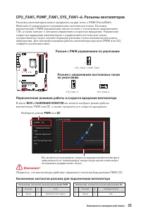
25 Компоненты материнской платы CPU_FAN1, PUMP_FAN1, SYS_FAN1~6: Разъемы вентиляторов Разъемы вентиляторов можно разделить на два типа: с PWM (PulseWidth Modulation) управлением и управлением постоянным током. Разъемы вентиляторов с PWM управлением имеют контакт с постоянным напряжением 12В, а также...
Page 172 - JCI1: Разъем датчика открытия корпуса; Использование датчика открытия корпуса
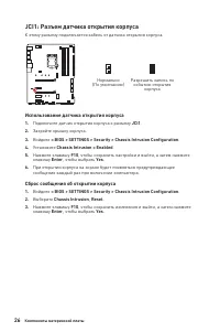
26 Компоненты материнской платы JCI1: Разъем датчика открытия корпуса К этому разъему подключается кабель от датчика открытия корпуса. Нормально (По умолчанию) Разрешить запись по событию открытия корпуса Использование датчика открытия корпуса 1. Подключите датчик открытия корпуса к разъему JCI1 . 2...
Page 173 - JTBT1: Разъем для установки карты расширения
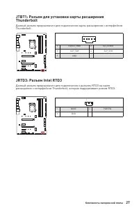
27 Компоненты материнской платы JTBT1: Разъем для установки карты расширения Thunderbolt Данный разъем предназначен для подключения карты расширения с интерфейсом Thunderbolt. JRTD3: Разъем Intel RTD3 Данный разъем предназначен для подключения к разъему RTD3 на карте расширения с интерфейсом Thunder...
Page 174 - BIOS; Сброс настроек BIOS до значений по умолчанию
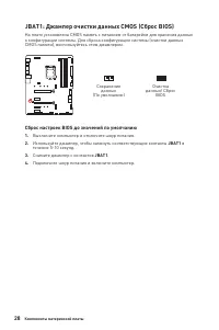
28 Компоненты материнской платы JBAT1: Джампер очистки данных CMOS (Сброс BIOS) На плате установлена CMOS память с питанием от батарейки для хранения данных о конфигурации системы. Для сброса конфигурации системы (очистки данных CMOS памяти), воспользуйтесь этим джампером. Сохранение данных (По умол...
Page 175 - обесточить систему и отключить кабель питания.; JRGB1: Разъем RGB LED; Подключение RGB светодиодных лент
29 Компоненты материнской платы ⚠ Внимание! ∙ Разъем JRGB поддерживает подключение 5050 RGB непрерывных светодиодных лент (12В/G/R/B) длиной до 2 метров с максимальной мощностью 3А (12В). ∙ Перед установкой или заменой светодиодных лент RGB, необходимо полностью обесточить систему и отключить кабель...
Page 176 - светодиодных лент 5В к разъему JRGB приведет к их повреждению.; Подключение адресных RGB светодиодных лент
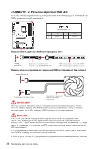
30 Компоненты материнской платы 1 1 1 D +5V ⚠ ВНИМАНИЕ! Не подключайте несовместимые с материнской платой светодиодные ленты. Разъем JRGB и разъем JRAINBOW имеют разное напряжение, и подключение светодиодных лент 5В к разъему JRGB приведет к их повреждению. ⚠ Внимание! ∙ Разъем JRAINBOW поддерживает...
Page 177 - Индикаторы отладки EZ; - память DRAM не обнаружена или повреждена.; - видеокарта не обнаружена или повреждена.; - устройство загрузки не обнаружено или; Встроенные индикаторы; LED_SW1: Переключатель для управления индикаторами EZ; на материнской плате.
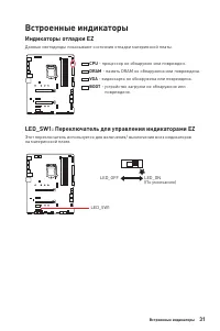
31 Встроенные индикаторы Индикаторы отладки EZ Данные светодиоды показывают состояния отладки материнской платы. CPU - процессор не обнаружен или поврежден. DRAM - память DRAM не обнаружена или повреждена. VGA - видеокарта не обнаружена или повреждена. BOOT - устройство загрузки не обнаружено или по...
Page 178 - Установка ОС, драйверов и утилит; Установка Windows® 10
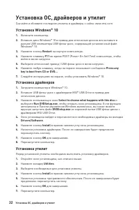
32 Установка ОС, драйверов и утилит Установка ОС, драйверов и утилит Скачайте и обновите последние утилиты и драйверы с сайта: www.msi.com Установка Windows® 10 1. Включите компьютер. 2. Вставьте диск Windows® 10 в привод для оптических дисков или вставьте в разъем USB компьютера USB флэш-диск, соде...
Page 179 - Преимущества UEFI; ∙ 32-битная ОС Windows; Как проверить режим BIOS?; Режим загрузки UEFI
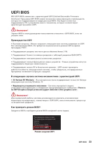
33 UEFI BIOS UEFI BIOS MSI UEFI BIOS совместим с архитектурой UEFI (Unified Extensible Firmware Interface). Прошивка UEFI BIOS имеет множество новых функций и преимуществ, которые не поддерживаются традиционным BIOS. Она будет полностью поддерживать ПК и устройства нового поколения, которые соответс...
Page 180 - Настройка BIOS; всегда устанавливайте настройки по умолчанию; Вход в настройки BIOS; Функциональные клавиши
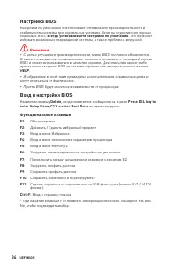
34 UEFI BIOS Настройка BIOS Настройки по умолчанию обеспечивают оптимальную производительность и стабильность системы при нормальных условиях. Если вы недостаточно хорошо знакомы с BIOS, всегда устанавливайте настройки по умолчанию . Это позволит избежать возможных повреждений системы, а также пробл...
Page 181 - Сброс BIOS; очистки данных CMOS; Обновление BIOS; Обновление BIOS при помощи M-FLASH; Yes
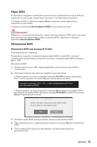
35 UEFI BIOS Сброс BIOS В некоторых ситуациях необходимо выполнить восстановление настроек BIOS до значений по умолчанию. Существует несколько способов сброса настроек: ∙ Войдите в BIOS и нажмите клавишу F6 для загрузки оптимизированных значений по умолчанию. ∙ Замкните джампер очистки данных CMOS н...
Page 182 - Обновление BIOS при помощи MSI DRAGON CENTER
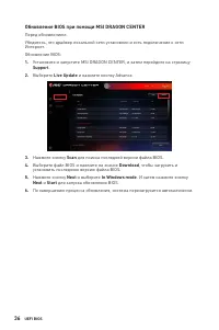
36 UEFI BIOS Обновление BIOS при помощи MSI DRAGON CENTER Перед обновлением:Убедитесь, что драйвер локальной сети установлен и есть подключение к сети Интернет. Обновление BIOS: 1. Установите и запустите MSI DRAGON CENTER, и затем перейдите на страницу Support . 2. Выберите Live Update и нажмите кно...
Page 183 - Режим EZ; CREATOR GENIE
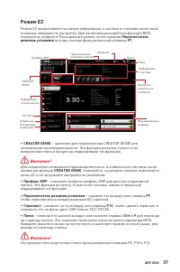
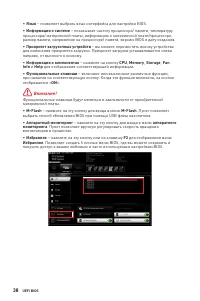
37 UEFI BIOS Режим EZ Режим EZ предоставляет основную информацию о системе и позволяет выполнить основные операции по настройке. Для настройки расширенных функций BIOS, пожалуйста, войдите в Расширенный режим, путем нажатия Переключатель режимов установки или при помощи функциональной клавиши F7 . П...
Page 185 - ▪ Добавление пункта BIOS в меню Избранное
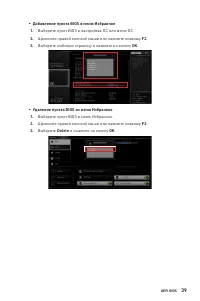
39 UEFI BIOS ▪ Добавление пункта BIOS в меню Избранное 1. Выберите пункт BIOS в настройках OC или меню OC. 2. Щелкните правой кнопкой мыши или нажмите клавишу F2 . 3. Выберите любимую страницу и нажмите на кнопку OK . ▪ Удаление пункта BIOS из меню Избранное 1. Выберите пункт BIOS в меню Избранное. ...
Page 186 - Режим разгона; переключатель режимов установки; ∙ Выбор меню BIOS
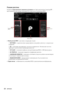
40 UEFI BIOS Режим разгона Нажмите переключатель режимов установки или функциональную клавишу F7 для переключения между режимами EZ и разгона в настройках BIOS. Выбор меню BIOS Экран меню Выбор меню BIOS ∙ Выбор меню BIOS – доступны следующие опции: ▪ SETTINGS – в данном меню представлены настройки ...
Page 187 - Меню OC
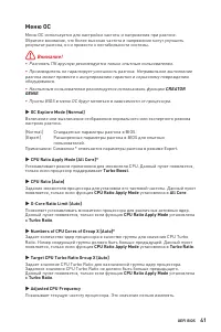
41 UEFI BIOS Меню OC Меню OC используется для настройки частоты и напряжения при разгоне. Обратите внимание, что более высокая частота и напряжение могут улучшить результат разгона, но и привести к нестабильности системы. ⚠ Внимание! ∙ Разгонять ПК вручную рекомендуется только опытным пользователям....
Page 193 - Regulatory Notices; クラスB情報技術装置
i Regulatory Notices Regulatory Notices FCC Compliance Statement Note: This equipment has been tested and found to comply with the limits for a Class B digital device, pursuant to part 15 of the FCC Rules. These limits are designed to provide reasonable protection against harmful interference in a r...
Page 194 - ii
ii Regulatory Notices and electronic equipment” cannot be discarded as municipal wastes anymore, and manufacturers of covered electronic equipment will be obligated to take back such products at the end of their useful life. MSI will comply with the product take back requirements at the end of life ...
Page 195 - iii; India RoHS
iii Regulatory Notices ČESKY Záleží nám na ochraně životního prostředí - společnost MSI upozorňuje...Podle směrnice Evropské unie (“EU”) o likvidaci elektrických a elektronických výrobků 2002/96/ EC platné od 13. srpna 2005 je zakázáno likvidovat “elektrické a elektronické výrobky” v běžném komunáln...
Page 196 - iv; MS-7C75主板产品中有害物质的名称及含量
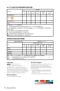
iv Regulatory Notices MS-7C75主板产品中有害物质的名称及含量 部件名称 有害物质 铅 (Pb) 汞 (Hg) 镉 (Cd) 六价铬 (Cr(VI)) 多溴联苯 (PBB) 多溴二苯醚 (PBDE) 印刷电路板组件* ╳ ○ ○ ○ ○ ○ 电池** ╳ ○ ○ ○ ○ ○ 外部信号连接头 ╳ ○ ○ ○ ○ ○ 线材 ╳ ○ ○ ○ ○ ○ 本表格依据 SJ/T 11364 的规定编制。○: 表示该有害物质在该部件所有均质材料中的含量均在 GB/T 26572 规定的限量要求以下。╳: 表示该有害物质至少在该部件的某一均质材料中的含量超出 GB/T 26572 规定...