Page 2 - Safety Information
2 Quick Start Safety Information ∙ The components included in this package are prone to damage from electrostatic discharge (ESD). Please adhere to the following instructions to ensure successful computer assembly. ∙ Ensure that all components are securely connected. Loose connections may cause the ...
Page 3 - Installing a Processor
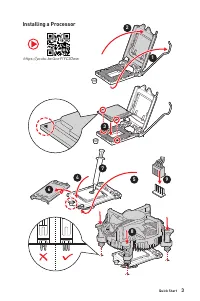
3 Quick Start https://youtu.be/4ce91YC3Oww Installing a Processor 1 2 3 6 4 5 7 8 9
Page 4 - Installing DDR4 memory
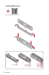
4 Quick Start Installing DDR4 memory http://youtu.be/T03aDrJPyQs DIMMA2 DIMMA2 DIMMB2 DIMMA1 DIMMA2 DIMMB1 DIMMB2
Page 5 - HDD LED; Connecting the Front Panel Header
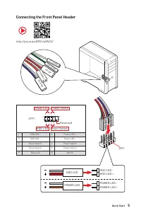
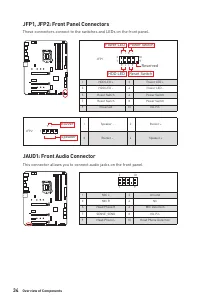
5 Quick Start HDD LED RESET SW Connecting the Front Panel Header http://youtu.be/DPELIdVNZUI JFP1 HDD LED HDD LED - HDD LED + POWER LED -POWER LED + POWER LED 1 2 10 9 + + + - - - - + Power LED HDD LED Reset Switch Reserved Power Switch JFP1 1 HDD LED + 2 Power LED + 3 HDD LED - 4 Power LED - 5 Rese...
Page 6 - Installing the Motherboard
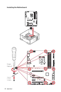
6 Quick Start BAT1 Installing the Motherboard 1 Torque:3 kgf·cm* *3 kgf·cm= 0.3 N·m= 2.6 lbf·in 2
Page 7 - Connecting the Power Connectors
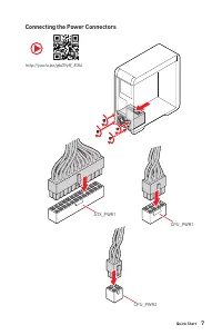
7 Quick Start Connecting the Power Connectors http://youtu.be/gkDYyR_83I4 ATX_PWR1 CPU_PWR1 CPU_PWR2
Page 8 - Installing SATA Drives
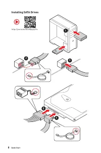
8 Quick Start Installing SATA Drives http://youtu.be/RZsMpqxythc 1 2 3 4 5
Page 9 - Installing a Graphics Card
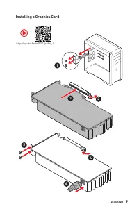
9 Quick Start Installing a Graphics Card 1 http://youtu.be/mG0GZpr9w_A 2 3 4 5 6
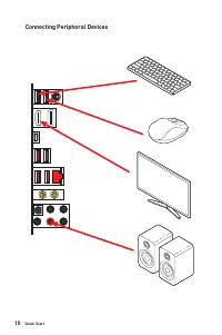
Page 10 - Connecting Peripheral Devices
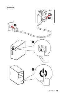
Page 11 - Power On
Page 12 - Contents
12 Contents Contents Quick Start ............................................................................................................. 1 Preparing Tools and Components .......................................................................... 1Safety Information ................................
Page 13 - Intel
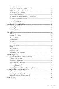
13 Contents JCOM1: Serial Port Connector ............................................................................. 39JBAT1: Clear CMOS (Reset BIOS) Jumper ........................................................... 40JTBT1: Thunderbolt Add-on Card Connector .........................................
Page 14 - Specifications; CPU
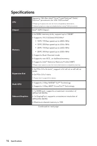
14 Specifications Specifications CPU Supports 10th Gen Intel® Core™ and Pentium® Gold / Celeron® processors for LGA 1200 socket* * Please go to www.intel.com for more compatibility information.* Onboard graphics output are disabled when using F SKU processors. Chipset Intel® Z490 Chipset Memory ∙ 4x...
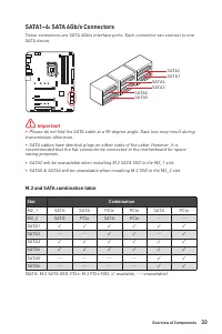
Page 15 - Storage
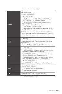
15 Specifications Continued from previous page Storage Intel® Z490 Chipset ∙ 6x SATA 6Gb/s ports*/** ∙ 2x M.2 slots (Key M) ▪ M2_1 supports up to PCIe 3.0 x4 and SATA 6Gb/s, 2242/ 2260/ 2280/ 22110 storage devices* ▪ M2_2 supports up to PCIe 3.0 x4 and SATA 6Gb/s, 2242/ 2260/ 2280 storage devices** ...
Page 16 - Bluetooth
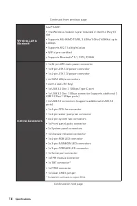
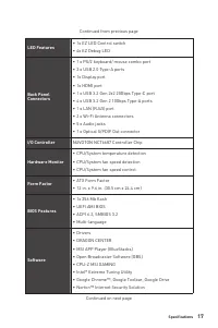
16 Specifications Continued from previous page Wireless LAN & Bluetooth ® Intel® AX201 ∙ The Wireless module is pre-installed in the M.2 (Key-E) slot ∙ Supports MU-MIMO TX/RX, 2.4GHz/ 5GHz (160MHz) up to 2.4Gbps ∙ Supports 802.11 a/b/g/n/ac/ax ∙ WiFi 6 pre-certified ∙ Supports Bluetooth® 5.1, FI...
Page 18 - Dragon Center; Special Features
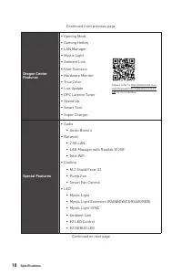
18 Specifications Continued from previous page Dragon Center Features ∙ Gaming Mode ∙ Gaming Hotkey ∙ LAN Manager ∙ Mystic Light ∙ Ambient Link ∙ User Scenario ∙ Hardware Monitor ∙ True Color ∙ Live Update ∙ DPC Latency Tuner ∙ Speed Up ∙ Smart Tool ∙ Super Charger Please refer to http://download.ms...
Page 19 - JCORSAIR1 Connector Specification; Supporting CORSAIR RGB Products
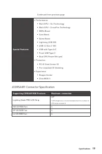
19 Specifications Continued from previous page Special Features ∙ Performance ▪ Multi GPU – SLI Technology ▪ Multi GPU – CrossFire Technology ▪ DDR4 Boost ▪ Core Boost ▪ Game Boost ▪ Lightning USB 20G ▪ USB 3.2 Gen 2 10G ▪ USB with Type A+C ▪ Front USB Type-C ▪ Dual CPU Power (8+4 pin) ∙ Protection ...
Page 20 - Package contents; Motherboard; Important
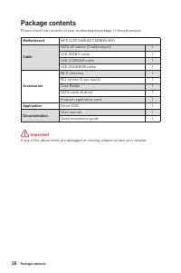
20 Package contents Package contents Please check the contents of your motherboard package. It should contain: Motherboard MPG Z490 GAMING CARBON WIFI Cable SATA 6G cables (2 cables/pack) 1 LED JRGB Y cable 1 LED JCORSAIR cable 1 LED JRAINBOW cable 1 Accessories Wi-Fi Antenna 1 M.2 screws (3 pcs./pa...
Page 21 - Block Diagram
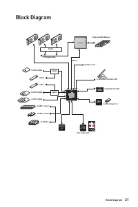
21 Block Diagram Block Diagram 1x USB 3.2 Gen2 x 2 2 Channel DDR4 Memory DMI 3.0 PCI Express Bus PCH Processor NUVOTON 6687 Realtek ALC1220P ASMEDIA 3241 5x USB 3.2 Gen2 6x USB 2.0 2x PCIe x1 slot JHL7540 Rear Audio Jacks Switch 1x Realtek 2.5G LAN 1x Intel AX201 Wireless LAN 2x USB 3.2 Gen1 1x M.2 ...
Page 22 - Audio Ports Configuration; Speed LED; LAN Port LED Status Table; Audio Ports
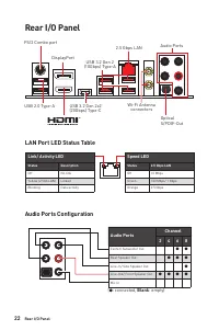
22 Rear I/O Panel USB 3.2 Gen 2x2 (20Gbps) Type-C Audio Ports Configuration Rear I/O Panel PS/2 Combo port 2.5 Gbps LAN DisplayPort USB 2.0 Type-A Audio Ports Optical S/PDIF-Out Wi-Fi Antenna connectors USB 3.2 Gen 2 (10Gbps) Type-A Link/ Activity LED Status Description Off No link Yellow (2.5Gb LAN...
Page 23 - Realtek Audio Console; Auto popup dialog
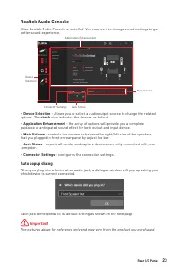
23 Rear I/O Panel Realtek Audio Console After Realtek Audio Console is installed. You can use it to change sound settings to get better sound experience. ∙ Device Selection - allows you to select a audio output source to change the related options. The check sign indicates the devices as default. ∙ ...
Page 25 - Installing Antennas
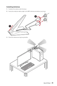
25 Rear I/O Panel Installing Antennas 1. Combine the antenna with the base. 2. Screw two antenna cables tight to the WiFi antenna connectors as shown. 1 2 3. Place the antenna as high as possible.
Page 26 - Overview of Components
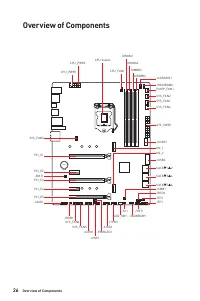
26 Overview of Components BAT1 Overview of Components JRAINBOW1 JFP1 JTBT1 JRGB1 SATA▼1▲2 SYS_FAN3 JUSBC1 JUSB3 SATA▼3▲4 SATA▼5▲6 JFP2 JRTD3 M2_1 JSMB1 M2_2 CPU_FAN1 SYS_FAN2 PUMP_FAN1 PCI_E1 PCI_E2 PCI_E3 JBAT1 PCI_E4 PCI_E5 JCI1 LED_SW1 CPU Socket CPU_PWR1 CPU_PWR2 SYS_FAN1SYS_FAN6 JRAINBOW2 JCORS...
Page 27 - Component Contents; Port Name
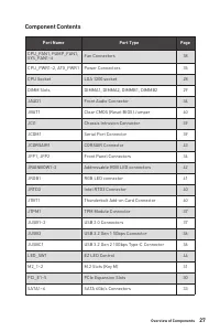
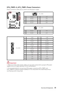
27 Overview of Components Component Contents Port Name Port Type Page CPU_FAN1, PUMP_FAN1, SYS_FAN1~6 Fan Connectors 38 CPU_PWR1~2, ATX_PWR1 Power Connectors 35 CPU Socket LGA 1200 socket 28 DIMM Slots DIMMA1, DIMMA2, DIMMB1, DIMMB2 29 JAUD1 Front Audio Connector 34 JBAT1 Clear CMOS (Reset BIOS) Jum...
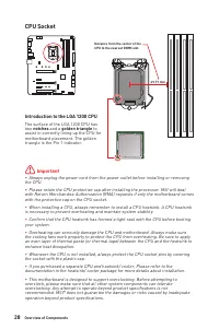
Page 28 - CPU Socket; Introduction to the LGA 1200 CPU; notches
28 Overview of Components ⚠ Important ∙ Always unplug the power cord from the power outlet before installing or removing the CPU. ∙ Please retain the CPU protective cap after installing the processor. MSI will deal with Return Merchandise Authorization (RMA) requests if only the motherboard comes wi...
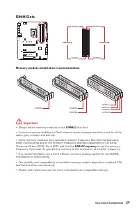
Page 29 - DIMM Slots; Memory module installation recommendation; DRAM Frequency
29 Overview of Components DIMM Slots DIMMA1 DIMMB1 Channel A Channel B DIMMA2 DIMMB2 Memory module installation recommendation ⚠ Important ∙ Always insert memory modules in the DIMMA2 slot first. ∙ To ensure system stability for Dual channel mode, memory modules must be of the same type, number and ...
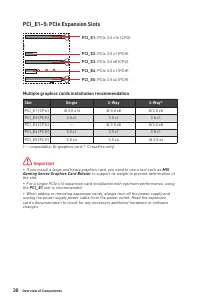
Page 30 - Multiple graphics cards installation recommendation; Slot; MSI
30 Overview of Components Multiple graphics cards installation recommendation Slot Single 2-Way 3-Way* PCI_E1 (CPU) @ 3.0 x16 @ 3.0 x8 @ 3.0 x8 PCI_E2 (PCH) 3.0 x1 3.0 x1 3.0 x1 PCI_E3 (CPU) — @ 3.0 x8 @ 3.0 x8 PCI_E4 (PCH) 3.0 x1 3.0 x1 3.0 x1 PCI_E5 (PCH) 3.0 x4 3.0 x4 @ 3.0 x4 (─: unavailable, @:...
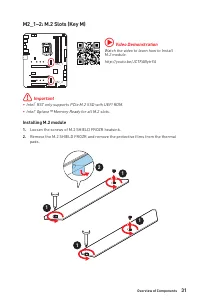
Page 31 - Installing M.2 module; Video Demonstration
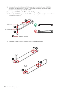
31 Overview of Components M2_1~2: M.2 Slots (Key M) Installing M.2 module 1. Loosen the screws of M.2 SHIELD FROZR heatsink. 2. Remove the M.2 SHIELD FROZR and remove the protective films from the thermal pads. 2 1 1 1 1 M2_1 M2_2 ⚠ Important ∙ Intel ® RST only supports PCIe M.2 SSD with UEFI ROM. ∙...
Page 34 - JAUD1: Front Audio Connector
34 Overview of Components JAUD1: Front Audio Connector This connector allows you to connect audio jacks on the front panel. 1 2 10 9 1 MIC L 2 Ground 3 MIC R 4 NC 5 Head Phone R 6 MIC Detection 7 SENSE_SEND 8 No Pin 9 Head Phone L 10 Head Phone Detection JFP1, JFP2: Front Panel Connectors These conn...
Page 37 - JTPM1: TPM Module Connector
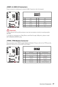
37 Overview of Components JUSB1~2: USB 2.0 Connectors These connectors allow you to connect USB 2.0 ports on the front panel. 1 2 10 9 1 VCC 2 VCC 3 USB0- 4 USB1- 5 USB0+ 6 USB1+ 7 Ground 8 Ground 9 No Pin 10 NC ⚠ Important ∙ Note that the VCC and Ground pins must be connected correctly to avoid pos...
Page 38 - Switching fan mode and adjusting fan speed; HARDWARE MONITOR; Pin definition of fan connectors
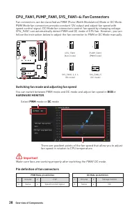
38 Overview of Components CPU_FAN1, PUMP_FAN1, SYS_FAN1~6: Fan Connectors Fan connectors can be classified as PWM (Pulse Width Modulation) Mode or DC Mode. PWM Mode fan connectors provide constant 12V output and adjust fan speed with speed control signal. DC Mode fan connectors control fan speed by ...
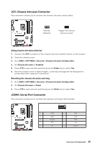
Page 39 - JCI1: Chassis Intrusion Connector; Using chassis intrusion detector; JCOM1: Serial Port Connector
39 Overview of Components JCI1: Chassis Intrusion Connector This connector allows you to connect the chassis intrusion switch cable. Normal (default) Trigger the chassis intrusion event Using chassis intrusion detector 1. Connect the JCI1 connector to the chassis intrusion switch/ sensor on the chas...
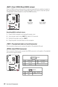
Page 40 - Resetting BIOS to default values; JRTD3: Intel RTD3 Connector
40 Overview of Components JBAT1: Clear CMOS (Reset BIOS) Jumper There is CMOS memory onboard that is external powered from a battery located on the motherboard to save system configuration data. If you want to clear the system configuration, set the jumpers to clear the CMOS memory. Keep Data (defau...
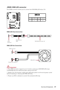
Page 41 - JRGB1: RGB LED connector; RGB LED Strip Connection
41 Overview of Components ⚠ Important ∙ The JRGB connector supports up to 2 meters continuous 5050 RGB LED strips (12V/G/R/B) with the maximum power rating of 3A (12V). ∙ Always turn off the power supply and unplug the power cord from the power outlet before installing or removing the RGB LED strip....
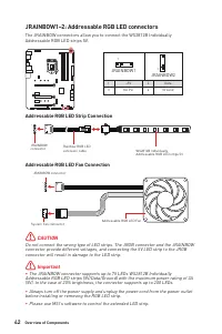
Page 42 - CAUTION; JRAINBOW1~2: Addressable RGB LED connectors; Addressable RGB LED Strip Connection
42 Overview of Components 1 1 1 D +5V ⚠ CAUTION Do not connect the wrong type of LED strips. The JRGB connector and the JRAINBOW connector provide different voltages, and connecting the 5V LED strip to the JRGB connector will result in damage to the LED strip. ⚠ Important ∙ The JRAINBOW connector su...
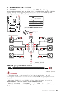
Page 43 - JCORSAIR1: CORSAIR Connector; CORSAIR RGB Fan Connection; CORSAIR Lighting Node PRO Connection
43 Overview of Components JCORSAIR1: CORSAIR Connector The JCORSAIR1 connector allows you to connect the CORSAIR Individually Addressable Lighting PRO RGB LED strips 5V or CORSAIR RGB fans with the CORSAIR fan hub. Once all items are connected properly, you can control the CORSAIR RGB LED strips and...
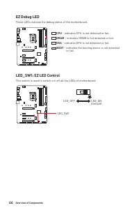
Page 44 - EZ Debug LED
44 Overview of Components EZ Debug LED These LEDs indicate the debug status of the motherboard. CPU - indicates CPU is not detected or fail. DRAM - indicates DRAM is not detected or fail. VGA - indicates GPU is not detected or fail. BOOT - indicates the booting device is not detected or fail. LED_SW...
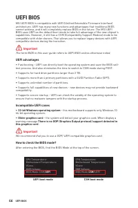
Page 46 - UEFI BIOS
46 UEFI BIOS UEFI BIOS MSI UEFI BIOS is compatible with UEFI (Unified Extensible Firmware Interface) architecture. UEFI has many new functions and advantages that traditional BIOS cannot achieve, and it will completely replace BIOS in the future. The MSI UEFI BIOS uses UEFI as the default boot mode ...
Page 47 - BIOS Setup; always keep the default settings; HELP; Entering BIOS Setup; Delete; Function key
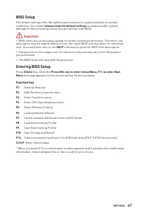
47 UEFI BIOS BIOS Setup The default settings offer the optimal performance for system stability in normal conditions. You should always keep the default settings to avoid possible system damage or failure booting unless you are familiar with BIOS. ⚠ Important ∙ BIOS items are continuously update for...
Page 48 - Resetting BIOS; Updating BIOS; Updating BIOS with M-FLASH
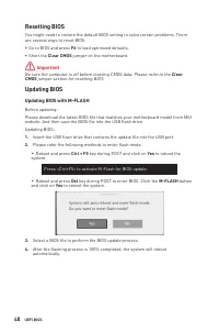
48 UEFI BIOS Resetting BIOS You might need to restore the default BIOS setting to solve certain problems. There are several ways to reset BIOS: ∙ Go to BIOS and press F6 to load optimized defaults. ∙ Short the Clear CMOS jumper on the motherboard. ⚠ Important Be sure the computer is off before clear...
Page 49 - Updating the BIOS with MSI DRAGON CENTER
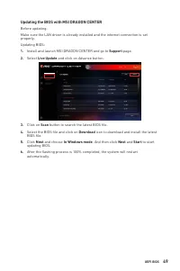
49 UEFI BIOS Updating the BIOS with MSI DRAGON CENTER Before updating:Make sure the LAN driver is already installed and the internet connection is set properly. Updating BIOS: 1. Install and launch MSI DRAGON CENTER and go to Support page. 2. Select Live Update and click on Advance button. 3. Click ...
Page 50 - EZ Mode
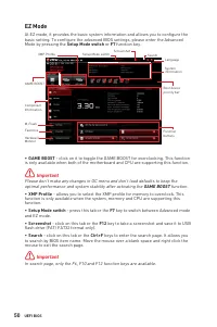
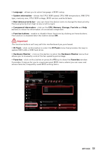
50 UEFI BIOS EZ Mode At EZ mode, it provides the basic system information and allows you to configure the basic setting. To configure the advanced BIOS settings, please enter the Advanced Mode by pressing the Setup Mode switch or F7 function key. XMP Profile Component Information System information ...
Page 52 - To add a BIOS item to a favorite menu
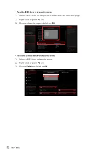
52 UEFI BIOS ▪ To add a BIOS item to a favorite menu 1. Select a BIOS item not only on BIOS menu but also on search page. 2. Right-click or press F2 key. 3. Choose a favorite page and click on OK. ▪ To delete a BIOS item from favorite menu 1. Select a BIOS item on favorite menu. 2. Right-click or pr...
Page 53 - Advanced Mode
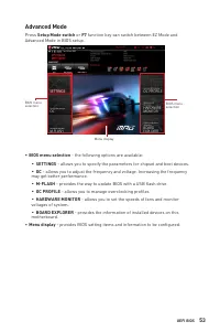
53 UEFI BIOS Advanced Mode Press Setup Mode switch or F7 function key can switch between EZ Mode and Advanced Mode in BIOS setup. BIOS menu selection Menu display BIOS menu selection ∙ BIOS menu selection - the following options are available: ▪ SETTINGS - allows you to specify the parameters for ch...
Page 54 - SETTINGS Menu
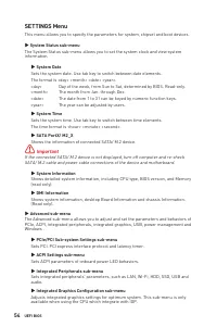
54 UEFI BIOS SETTINGS Menu This menu allows you to specify the parameters for system, chipset and boot devices. ▶ System Status sub-menu The System Status sub-menu allows you to set the system clock and view system information. ▶ System Date Sets the system date. Use tab key to switch between date e...
Page 56 - OC Menu
56 UEFI BIOS OC Menu This menu allows you to configure the frequencies and voltages for overclocking. Please note that, higher frequency and voltage may benefit overclocking capability but cause system un-stability. ⚠ Important ∙ Overclocking your PC manually is only recommended for advanced users. ...
Page 57 - ▶ CPU Ratio Offset When Running AVX [Auto]
57 UEFI BIOS ▶ Core X X of X xxxx MHz [Auto] Allows you to set the CPU ratios for different number of active cores. These items only appear when CPU Ratio Apply Mode set to Per Core . ▶ Turbo Ratio Offset Value [Auto] Sets the CPU Turbo ratio offset value. This item only appears when CPU Ratio Apply...
Page 58 - ▶ Advanced DRAM Configuration
58 UEFI BIOS ▶ Clockgen Features sub-menu Press Enter to enter the sub-menu. Sets the detailed clockgen features. ▶ Extreme Memory Profile (XMP) [Disabled] XMP (Extreme Memory Profile) is the overclocking technology by memory module. Please enable XMP or select a profile of memory module for overclo...
Page 59 - ▶ CPU Specifications sub-menu
59 UEFI BIOS ▶ DRAM Voltages control [Auto] These options allow you to set the voltages related to memory. If set to Auto , BIOS will set these voltages automatically or you can set it manually. ▶ PCH Voltages control [Auto] These options allow you to set the voltages related to PCH. If set to Auto ...
Page 60 - Yes
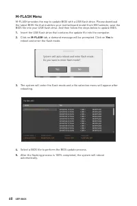
60 UEFI BIOS M-FLASH Menu M-FLASH provides the way to update BIOS with a USB flash drive. Please download the latest BIOS file that matches your motherboard model from MSI website, save the BIOS file into your USB flash drive. And then follow the steps below to update BIOS. 1. Insert the USB flash d...
Page 61 - OC PROFILE Menu; Enter; ▶ OC Profile Load from ROM; ▶ OC Profile Save to USB
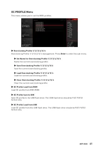
61 UEFI BIOS OC PROFILE Menu This menu allows you to set the BIOS profiles. ▶ Overclocking Profile 1/ 2/ 3/ 4/ 5/ 6 Overclocking Profile 1/ 2/ 3/ 4/ 5/ 6 management. Press Enter to enter the sub-menu. ▶ Set Name for Overclocking Profile 1/ 2/ 3/ 4/ 5/ 6 Name the current overclocking profile. ▶ Save ...
Page 62 - HARDWARE MONITOR Menu; Smart Fan; All Set Default; All Set Cancel
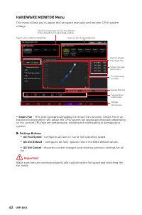
62 UEFI BIOS HARDWARE MONITOR Menu This menu allows you to adjust the fan speed manually and monitor CPU/ system voltage. Fan operating window Smart Fan duty information Click to enable the Smart Fan Temperature information Setting Buttons Select a fan to be configured Select a temperature curve lin...
Page 63 - Adjusting fans
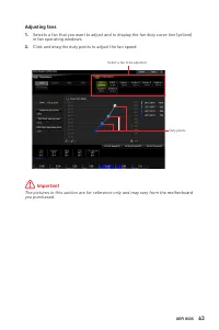
63 UEFI BIOS Adjusting fans 1. Selects a fan that you want to adjust and to display the fan duty curve line (yellow) in fan operating windows. 2. Click and drag the duty points to adjust the fan speed. Duty points Select a fan to be adjusted ⚠ Important The pictures in this section are for reference...
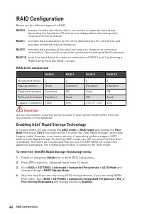
Page 64 - RAID level comparison; Enabling Intel; To enter the Intel(R) Rapid Storage Technology menu
RAID Configuration Below are the different types of a RAID. RAID 0 breaks the data into blocks which are written to separate hard drives. Spreading the hard drive I/O load across independent channels greatly improves I/O performance. RAID 1 provides data redundancy by mirroring data between the hard...
Page 65 - Creating RAID Volume
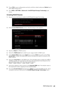
5. Press F10 to save configuration and exit, and then reboot and press Delete key to enter BIOS Setup menu. 6. Go to BIOS > SETTING > Advanced > Intel(R) Rapid Storage Technology sub- menu . Creating RAID Volume 1. As previously mentioned, enable Intel(R) Rapid Storage Technology. 2. Enter ...
Page 66 - Removing a RAID Volume; RAID VOLUME INFO
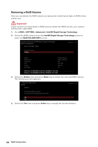
Removing a RAID Volume Here you can delete the RAID volume, but please be noted that all data on RAID drives will be lost. ⚠ Important If your system currently boots to RAID and you delete the RAID volume, your system will become unbootable. 1. Go to BIOS > SETTING > Advanced > Intel(R) Rap...
Page 67 - Resetting Disks to Non-RAID
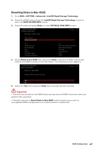
Resetting Disks to Non-RAID 1. Go to BIOS > SETTING > Advanced > Intel(R) Rapid Storage Technology . 2. Select the RAID volume from the Intel(R) Rapid Storage Technology screen to enter the RAID VOLUME INFO screen. 3. Select the disk and press Enter to enter PHYSICAL DISK INFO screen. 4. Se...
Page 68 - Rebuilding RAID Array
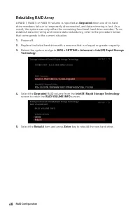
Rebuilding RAID Array A RAID 1, RAID 5 or RAID 10 volume is reported as Degraded when one of its hard drive members fails or is temporarily disconnected, and data mirroring is lost. As a result, the system can only utilize the remaining functional hard drive member. To re- establish data mirroring a...
Page 69 - Installing RAID Driver; New Operating System Installation; Installing Intel
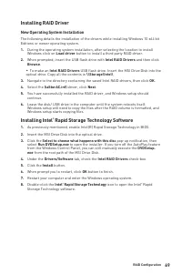
Installing RAID Driver New Operating System Installation The following details the installation of the drivers while installing Windows 10 x64 bit Editions or newer operating system. 1. During the operating system installation, after selecting the location to install Windows click on Load driver but...
Page 70 - System Requirements
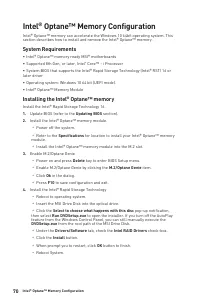
Intel® Optane™ Memory Configuration Intel® Optane™ memory can accelerate the Windows 10 64bit operating system. This section describes how to install and remove the Intel® Optane™ memory. System Requirements ∙ Intel® Optane™ memory ready MSI® motherboards ∙ Supported 8th Gen, or later, Intel ® Core™...
Page 71 - WARNING
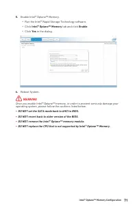
5. Enable Intel® Optane™ Memory. ▫ Run the Intel® Rapid Storage Technology software. ▫ Click Intel® Optane™ Memory tab and click Enable . ▫ Click Yes in the dialog. 6. Reboot System. ⚠ WARNING Once you enable Intel® Optane™ memory, in order to prevent seriously damage your operating system, please f...
Page 72 - Removing the Intel® OptaneTM memory
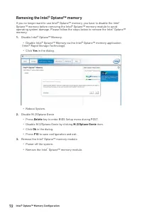
Removing the Intel® Optane™ memory If you no longer want to use Intel® Optane™ memory, you have to disable the Intel ® Optane™ memory before removing the Intel® Optane™ memory module to avoid operating system damage. Please follow the steps below to remove the Intel ® Optane™ memory. 1. Disable Inte...
Page 73 - Clear CMOS
Troubleshooting Before sending the motherboard for RMA repair, try to go over troubleshooting guide first to see if your got similar symptoms as mentioned below. The power is not on. ∙ Connect the AC power cord to an electrical outlet securely. ∙ Check if all ATX power connectors like ATX_PWR1, CPU_...
Page 74 - Regulatory Notices; KC인증서
74 Regulatory Notices Regulatory Notices FCC Compliance Statement Note: This equipment has been tested and found to comply with the limits for a Class B digital device, pursuant to part 15 of the FCC Rules. These limits are designed to provide reasonable protection against harmful interference in a ...
Page 76 - India RoHS
76 Regulatory Notices ČESKY Záleží nám na ochraně životního prostředí - společnost MSI upozorňuje...Podle směrnice Evropské unie (“EU”) o likvidaci elektrických a elektronických výrobků 2002/96/ EC platné od 13. srpna 2005 je zakázáno likvidovat “elektrické a elektronické výrobky” v běžném komunální...
Page 77 - MS-7C73主板产品中有害物质的名称及含量
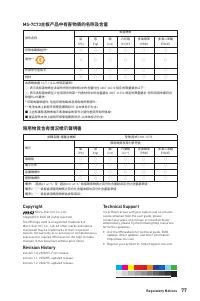
77 Regulatory Notices MS-7C73主板产品中有害物质的名称及含量 部件名称 有害物质 铅 (Pb) 汞 (Hg) 镉 (Cd) 六价铬 (Cr(VI)) 多溴联苯 (PBB) 多溴二苯醚 (PBDE) 印刷电路板组件* ╳ ○ ○ ○ ○ ○ 电池** ╳ ○ ○ ○ ○ ○ 外部信号连接头 ╳ ○ ○ ○ ○ ○ 线材 ╳ ○ ○ ○ ○ ○ 本表格依据 SJ/T 11364 的规定编制。○: 表示该有害物质在该部件所有均质材料中的含量均在 GB/T 26572 规定的限量要求以下。╳: 表示该有害物质至少在该部件的某一均质材料中的含量超出 GB/T 26572 规定...